![]()
QUICK REFERENCE GUIDE
MIDAS-M MULTI GAS TRANSMITTER
Fixed Single Point Extractive
Multi-Gas Transmitter
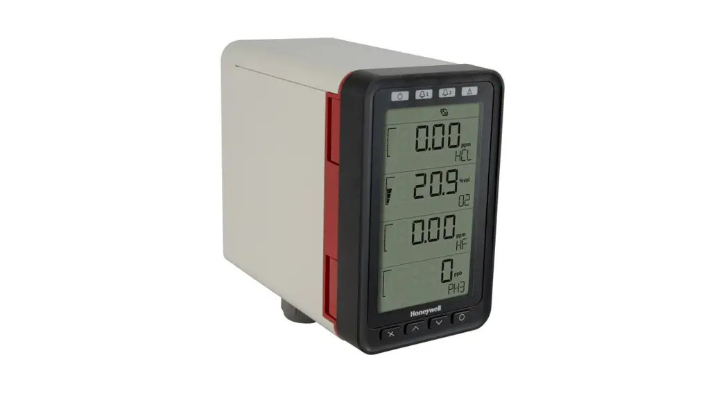
Introduction
The Midas-M® is a Fixed Extractive Single Point with 4-in 1 Multi-Gas Detector that draws a sample locally or from a remote point to a sensor cartridge that is located inside the detector’s chassis. A wide range of toxic, flammable, and oxygen gas sensor cartridges are available that enable the detection of gases used or generated in the Semiconductor and other manufacturing industries.
NOTE: Midas-M is shipped from the factory with the security function disabled. We strongly recommend enabling this function for the safe use of the detector. To enable it, select Set up > Security and type an 8 character password.
NOTE: Instrument grounding is required to ensure stable performance and to limit the effects of radiofrequency interference before installation.
Safety
![]() CAUTION
CAUTION
Failure to observe the following precautions can cause injury to persons or damage to property:
- To minimize the risk of electrostatic charging, provide a suitable ground connection, and install the equipment in such a way that no accidental discharges occur.
- When Midas-M reaches the end of its life, it should be disposed of by local regulations.
- Do not use cleaning solvents or abrasives to clean the gas detector.
- Do not attempt to modify the product in any way from the manufacturer’s design or specification. Warranty will be void and malfunction of the gas detector may result.
- Use only genuine spare parts and accessories with Midas-M. Malfunction may result if non-standard parts are used.
- • Midas-M is suitable for ordinary locations only and must not be installed in hazardous locations.
- Installation must be by the recognized standards of the appropriate authority in the country concerned. For Europe, see EN60079-14, EN60079-29-2, and EN61241-14. For installations in North America, the National Electrical Code (NFPA 70) should be strictly observed. All the appropriate local and national regulations should be observed.
Approvals
- Electrical UL/CSA/IEC/EN 610101
- EMC EN 50270
- ROHS
What’s in the Box
- 1 Transmitter device
- 2 Tubes (Large box only)
- 1 Quick Reference Guide
Overview
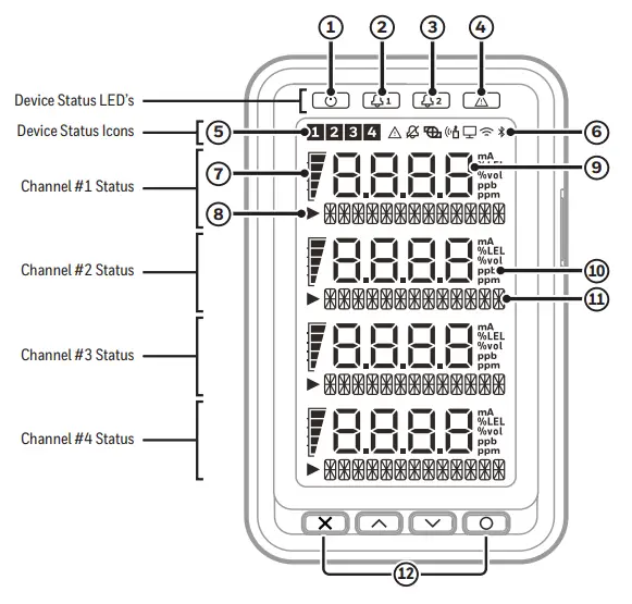
| 1. Power LED | 7. Bar graph for gas concentration display |
| 2. Alarm 1 LED | 8. Entry indicator for menu operation |
| 3. Alarm 2 LED | 9. Gas concentration |
| 4. Fault LED | 10. Unit |
| 5. Selected channel number indicator for menu operation | 11. Gas name, menu, fault message |
| 6. Device status icons | 12. Buttons |
| Wireless Connected | Fault | ||
| Bluetooth Connected | Inhibit | ||
| Internal pump running | Bump test in progress |
| Cancel | |
| Accept | |
| Up | |
| Down |
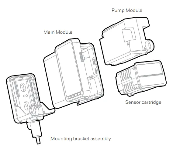
Mounting the Transmitter Device
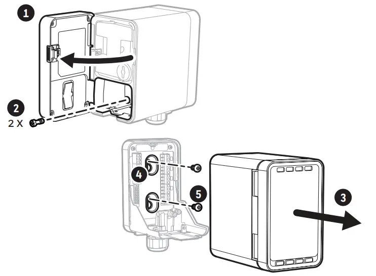
- Open the door
- Remove two screws
- Carefully pull main chassis forward
- Drill two holes 2.2 in
- • Partially screw the fixings into the mounting surface.
• Place the mounting bracket assembly over the screws, so they pass
through the mounting holes and then slide down to locate in the slots.
• Tighten the screws to secure the mounting bracket assembly. - • Align the rounded corner at the lower of the main module with the similar rounded corner at the bottom of the mounting bracket assembly
• Slide the main module backward while pushing the main module up after connecting with a mounting bracket so that the PCB and connector and tubes engage simultaneously. - Ensure the PCB, connector, and tubes are fully engaged by firmly pushing the main chassis horizontally backward on the mounting bracket assembly. DO NOT PUSH ON THE LCD AS THIS MAY DAMAGE IT.
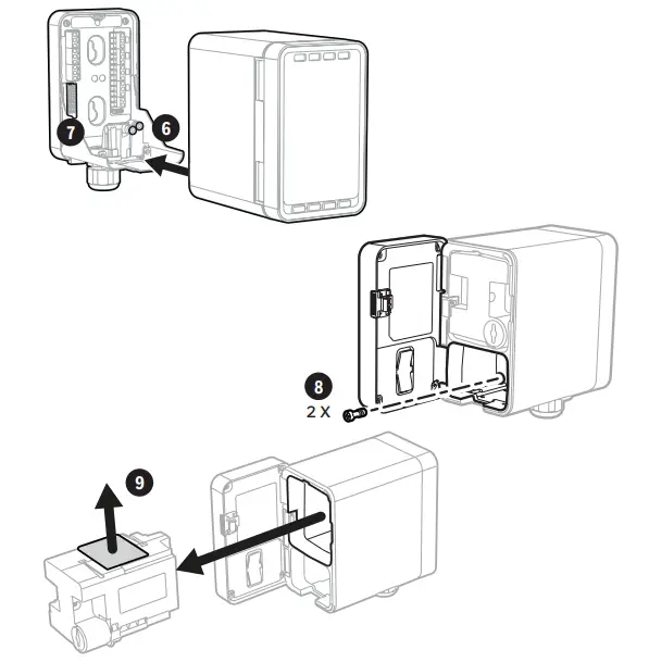
- • Align the two fixing screws located at the bottom of the chassis with the screw threads on the mounting bracket assembly.
• Tighten the screws to secure the chassis to the mounting bracket assembly. - Remove the internal packing card securing the pump. Failure to remove this packing will result in damage to the Midas-M detector.

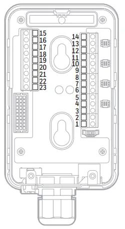
Transmitter Terminals
| Terminal Number | Function | Description |
| 1 | 24Vdc Input | 0Vdc |
| 2 | 24Vdc Input | +24Vdc |
| 3 | mA output – Channel 1 | COM |
| 4 | mA output – Channel 1 | mA- |
| 5 | mA output – Channel 1 | mA+ |
| 6 | mA output – Channel 2 | COM |
| 7 | mA output – Channel 2 | mA- |
| 8 | mA output – Channel 2 | mA+ |
| 9 | mA output – Channel 3 | COM |
| 10 | mA output – Channel 3 | mA- |
| 11 | mA output – Channel 3 | mA+ |
| 12 | mA output – Channel 4 | COM |
| 13 | mA output – Channel 4 | mA- |
| 14 | mA output – Channel 4 | mA+ |
| 15 | Relay 1 | Normally Closed |
| 16 | Relay 1 | Common |
| 17 | Relay 1 | Normally Open |
| 18 | Relay 2 | Normally Closed |
| 19 | Relay 2 | Common |
| 20 | Relay 2 | Normally Open |
| 21 | Relay 3 | Normally Closed |
| 22 | Relay 3 | Common |
| 23 | Relay 3 | Normally Open |
Commissioning
WARNING
Before carrying out any work, ensure local and site procedures are followed. Ensure that the associated control panel is inhibited to prevent false alarms. The following procedure should be followed carefully and only performed by suitably trained personnel.
- Ensure the detector is wired correctly.
- Ensure that the correct sensor cartridge is fitted. (If the cartridge has not been stored at room temperature, allow one hour for equilibration.)
- Ensure the on/off switch on the bottom of the mounting bracket assembly is in the on position.
- Apply power to the system.
- After the startup routine, the detector will display the normal operating mode.
- Perform a leak test to ensure all connections are secure.
- Waiting…’ will be displayed on booting time.
- Allow the detector to stabilize until the ‘Warm-up’ message is no longer displayed after booting. The maximum warm-up time is dependent on the sensor type. Refer to individual cartridge datasheets. Warm-up times are typically much faster.
- Ensure the correct ID code is selected in Set-up -> alarm menu
- If this is a first-time startup, the “Detect New Cartridge ~” message could be displayed. Press the ‘O’ button to clear the
message.
Specifications
| Operating Temperature: | 0°C~40°C |
| Physical: | |
| Size (unit with Sensor cartridge) | 136 mm(H) x 83 mm(W) x 152 mm (D) (5.35 x 3.27 x 5.98 in) |
| Weight – Sensor cartridge | 0.17 ~ 0.22 kg (0.38 ~ 0.49 lb) dependent on sensor type |
| Optional Relay Dimensions: | |
| Size | 137 mm (H) X 84 mm (W) X 41 mm (D) (5.39 X 3.31 X 1.61 in) |
| Weight | 0.31 kg (0.68 lb) |
| Power Requirements: | |
| Operating Voltage | 24 VDC Nominal 15 to +10% (20.4 to 26.4 VDC) |
| Operating Voltage with Power over Ethernet (PoE) | 48 VDC PoE (IEEE 802.3af compliant) |
| Power Consumption: | |
| Transmitter unit (normal condition)¹ | Typ. 5W |
| Transmitter unit (full load condition)² | < 11.45W |
| Transmitter with optional relay | < 12.9 W |
| Outputs: | |
| Visual | Alarm, power, fault LEDs, and LCD with all the gas readings and events. LEDs: Power(Green), Alarm 1 (Red), Alarm 2 (Red), Fault (Yellow) |
| Relays | Alarm1, Alarm2, Fault Relays (3) rated 1.0 A @ 30VDC or 1.0A @ 30Vdc or 0.5A @ 125Vac Max 10 uA @ 10 mV minimum, configurable as normally open or closed, latched or unlatched. |
| Analog | 3 wire sink, 3 wire source, or 4 wire fully isolated; 0 to 21 mA. for each channel. |
| DigitalCommunications | Modbus / TCP Ethernet / Power over Ethernet (PoE) |
| ¹ Normal condition: (1) No gas alarm (2) Without tube and pressure/vacuum ²Full load condition: (1) 4-ch gas alarms are on (2) Maximum tubing length and pressure/vacuum on the inlet/exhaust line | |
Contact Us
| Americas Honeywell Analytics 405 Barclay Boulevard Lincolnshire, IL 60069 Tel: +1 847 955 8200 Toll free: +1 800 538 0363 Fax: +1 847 955 8208 [email protected] | Asia Pacific, India. Honeywell Analytics Asia Pacific, Co., Ltd. 7F Sangam IT Tower, 434 Worldcup Buk-ro, Mapo-gu, Seoul 03922, South Korea Tel: +82 (0 2 6909 0300 Fax: +82 (0 2 2025 0388 India Tel: +91 124 4752 700 [email protected] |
| Europe, Middle East, and Africa Life Safety Distribution AG(LSD) Javastrasse 2 8604 Hegna Switzerland Tel: +41 (0)44 943 4300 Fax: +41 (0)44 943 4398 [email protected] | Mainland China Honeywell Industrial Safety Gas Detectors Building#1, 555 Huanke Road Zhang Jiang Hi-Tech Park Pudong New Area Shanghai 201203, China Tel: 021-80386800 Fax: 021-60246070 [email protected] |
| Taiwan Honeywell Taiwan Ltd 6F-2, No.8, ZiQiang S. Road, Jubei City, 30264 Taiwan Tel: +886-3-5169284 Fax: +886-3-5169339 [email protected] | |

Manuals and other information about this product are available at:
www.honeywellanalytics.com/en/products/Midas-M


