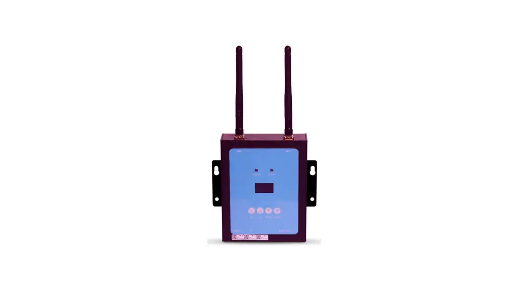
![]() RS485 Microinverter Controller MIC
RS485 Microinverter Controller MIC
Instruction Manual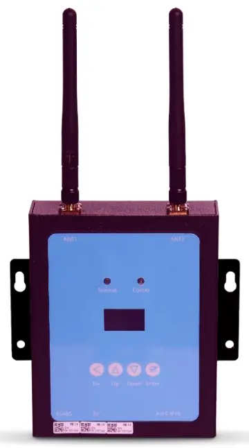
Read this manual before installing the controller and follow the instructions carefully during the installation process.
INTRODUCTION
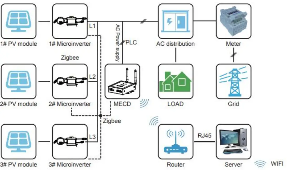
The MIC communications gateway collects and delivers modular performance data in real time, for comprehensive monitoring and management of your solar system, optimizing the performance of your solar system.
With built-in programmable DI, the MIC is able to control the shutdown of the connected microinverter immediately when the DI status is changed.
FEATURES
User-friendly
LCD display and buttons, easy operation.
Compact design and light in weight.
Capable
Built-in Zigbee, PLC and WIFI modular.
Compatible with single phase and three phase applications.
Enables remotely monitoring and management.
Safe
Support quick shutdown remotely for inverter.
Robust design, 3 years warranty.
GENERAL DESCRIPTION OF THE EQUIPMENT
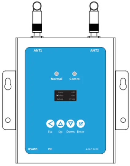
3.1. Interface description
All the MIC interfaces as below, from left to right, are Network port, DI and Power Connection Port.
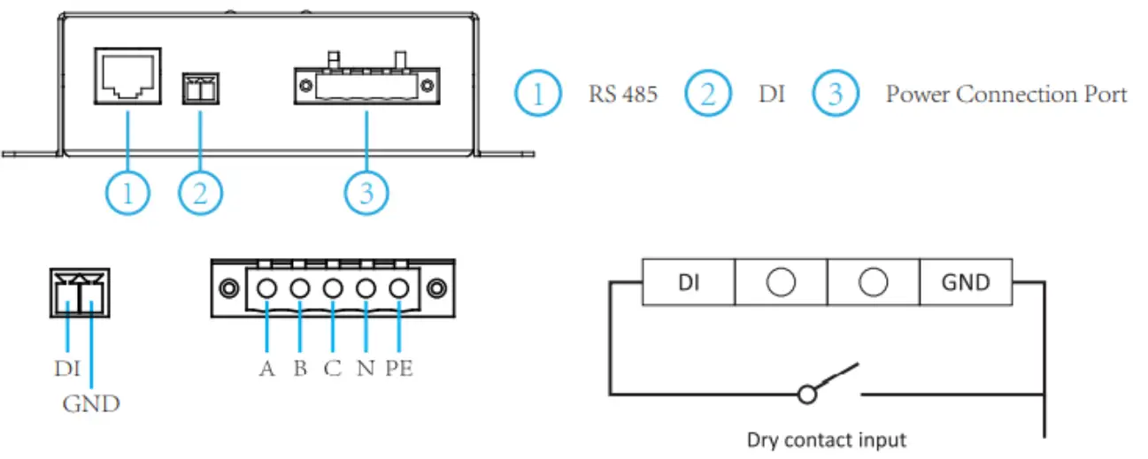 RS485: This port is for the communication with the meter.
DI: Digital input. When the DI status changes from 1 to 0, the MIC will send command to control the microinverter shutdown immediately via Zigbee or PLC.
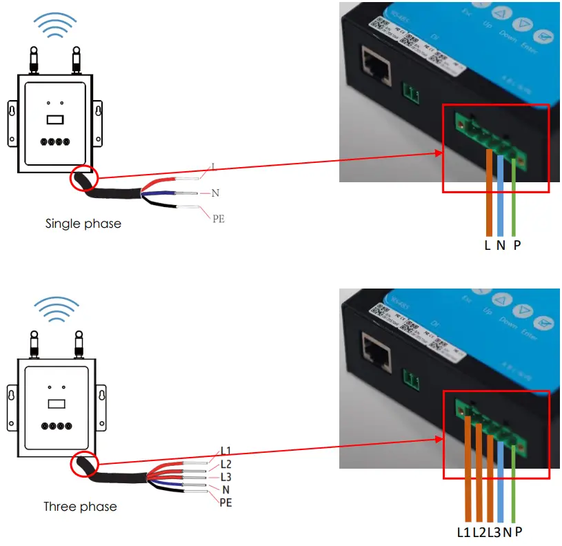
Power connection port: L1, L2, L3, N, PE, connects power through the power line. Power cable included in the MIC package.
3.2. Application Diagram
Single Phase System
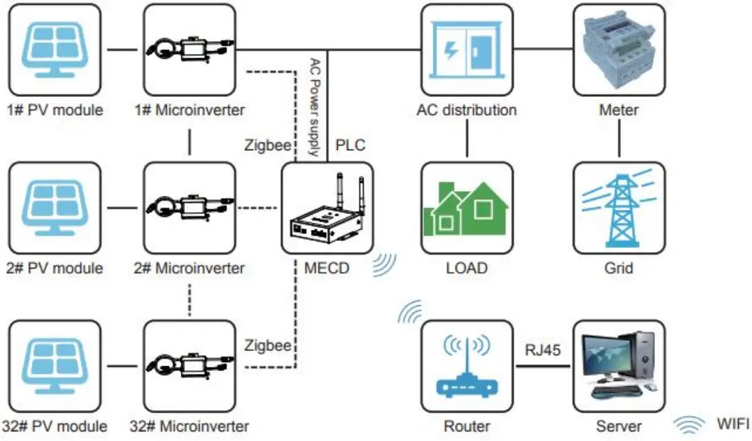
Three Phase System
INSTALLATION
Preparation
Make sure you have the following things taken care of before the installation:
- A dedicated standard AC electrical outlet (located electrically as close to the array as is possible).
- A broadband Internet connection is available for your use.
- Wireless router is available for you use a laptop.
- A web browser (to view the EMA online monitoring application).
- A pre-programmed MIC.
Selecting an Installation Location for the MIC
- A location that is electrically as close to the array as is possible preferably a dedicated outlet installed directly to the solar system subpanel.
- The MIC is not rated for outdoor use, so if installing outdoors near a junction box or breaker panel, making sure that you enclose it in an appropriate weatherproof NEMA electrical box.
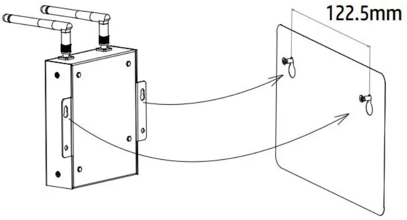
- Using wall-mounted. When mounting the MIC on the wall, make sure to select a cool, dry, indoor location.
- Depending on the wall surface you are mounting the MIC, use either two #4 drywall screws or wall anchors, installed 122.5 mm apart. The drywall screws and wall anchors are NOT included in the MIC kit.
- Align and slide the MIC onto the mounting screws.

Connections
- Connect the power cable to the power connection port on the bottom of the MIC.

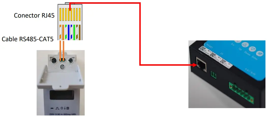
- Connect the meter to the MIC via RJ45 connector

OPERATION
5.1. Buttons
Once power is supplied to the MIC, it automatically steps into the main screens on its LCD display, which include detailed information below.
| Buttons | Name | Functions |
| Return button | Allows you to return to the last page or end an operation. | |
| Cursor Up button | Allows you to go to the upper- level menu or set parameters. | |
| Cursor Down button | Allows you to go to the lower-level menu or set parameters. | |
| Confirm button | Allows you to go to the menu or confirm the value. |
5.2. LED indications
There are two indicators in the MIC. The following description will tell how it works.
| Indicator | Status | Meaning |
| Normal indicator (left LED) | Steady blue | All inverters connected works normal |
| Off | All inverters connected has alarms | |
| Blinking blue | Some inverters connected has alarms | |
| Comm indicator (right LED) | Steady blue | All inverters connected communication successfully |
| Off | All inverters connected communication failed | |
| Blinking | Some inverters communication failed |
5.3. LCD display
Flow chart: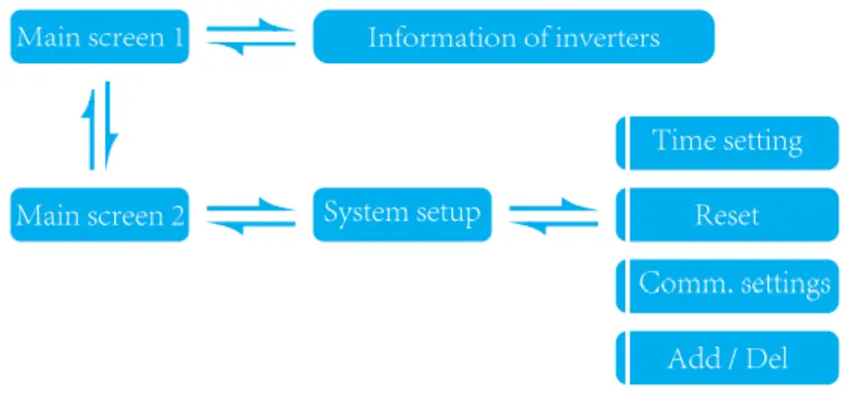 Screen 1: Inverters information
| MIC main interface 1 | MIC main interface 2 | Inverters information |
 | ||
| 1: Output power; 2: Today’s total power generation; 3: Total power generation of microinverters connected. | 1: version information. 2: Number of connected inverters. 3: Communication method. 4: MECD Serial number. | 1: Inverter ID currently connected; 2: Power generation; 3: Connection Status. |
Screen 2: System setup
| System setup | Time settings | Reset |
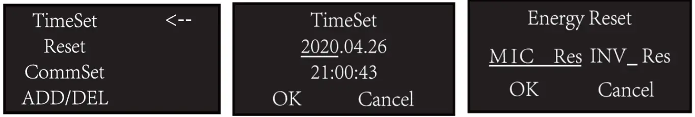 | ||
| 1: Time setting; 2: Reset; 3: Communication settings; 4: Add or Delete. | 1: MECD reset: reset to factory setting. 2: Inverter reset: clear all inverters information of MECD. | |
| Communication settings | Add or delete inverter ID on MIC | |
 | ||
| 1: Communication mode selection, Zigbee or PLC. | 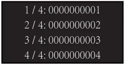 | 1: Introduce the microinverter serial number and add it. |
MONITORING
The MIC has built-in WIFI modular which is able to connect to router directly.
Web monitoring address:
 |  |
6.1. Set WiFi connection on PC
With a device that has Wi-Fi (PC, Tablet, Smartphone…) the connection with the MIC’s Wi-Fi is established:
- Open the wireless network connection.
- Click on See available wireless networks.
- Select the corresponding one with the device with which you want connect.
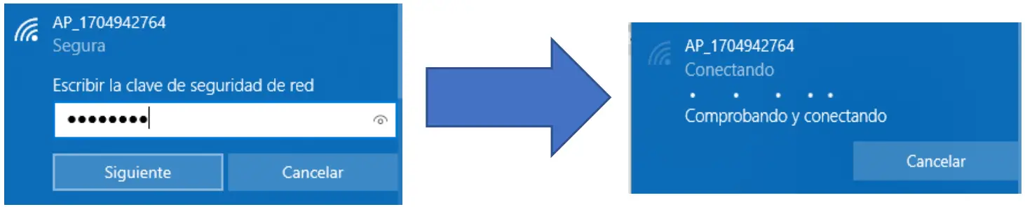
- The network name consists of AP and the serial number of the product.
- Input the password shown on the logger and click Connect.
- The default password for MICs is 12345678.
6.2. Connection with the logger
Once connected to WiFi:
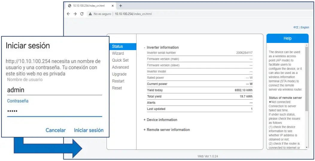
- Open a web browser.
- Type the following: 10.10.100.254
- Fill in username and password, both of which are admin as default.
- In the Status page, you can view general information of the logger.

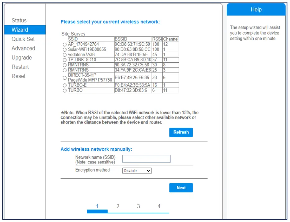
- Follow the setup wizard to start quick setting, click Wizard to start. Select the wireless network you need to connect, then click Next.

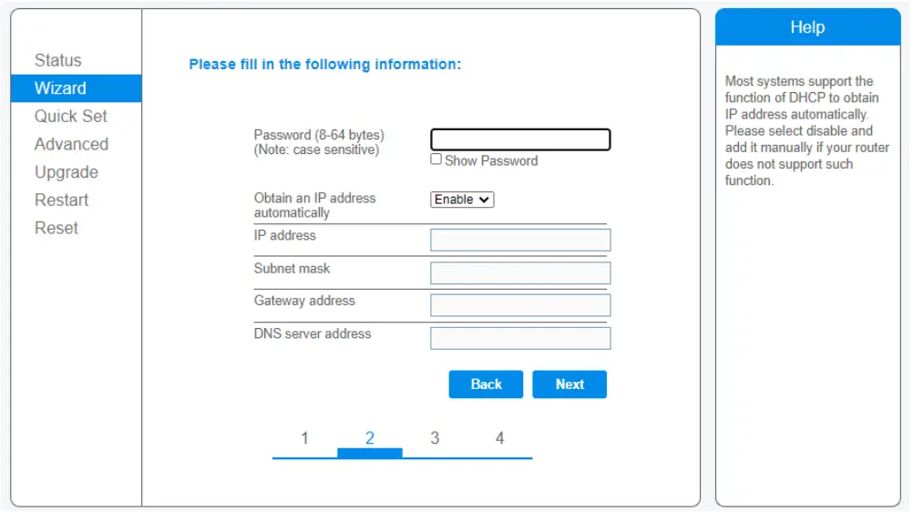
- Enter the password for the selected network, select Enable to obtain an IP address automatically, then click Next.

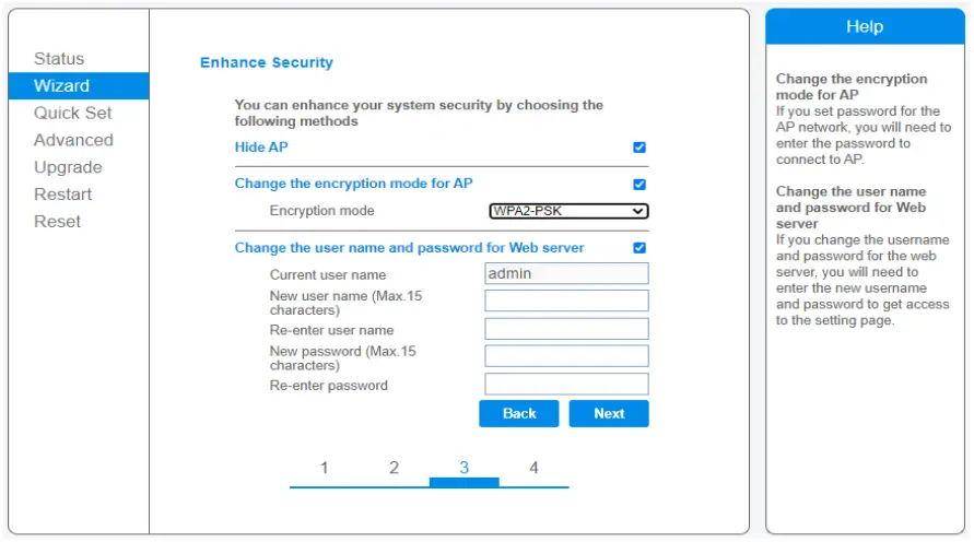
- Enhance security settings of the WiFi logger by selecting any options as listed, then click Next.

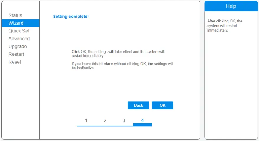
- If setting is successful, the following page will display. Click OK to restart.

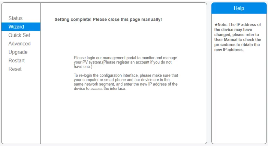
- If restart is successful, the following page will display. If this page does not display automatically, please refresh your browser.

- Re- log in this setting page to Status page after the Web server restart, and check the network connection status of the logger.
![]() We recommend not to change the password of the access portal or the password of the inverter’s Wi-Fi through the portal 10.10.100.254.
We recommend not to change the password of the access portal or the password of the inverter’s Wi-Fi through the portal 10.10.100.254.
If you forget the password, you will not be able to access the portal again to configure the WiFi.
DATASHEET
| Model | MIC |
| Communication | |
| Communication method | Zigbee, PLC |
| ‘. lax. number of inverters connected | 5. 10. 20. 32 (Max.) |
| Communication to router | WIFI |
| WIFI wireless security | WEP, WPA2-PSK |
| RS485 | Reserved |
| Max.distance(free space) | PLC 300m; Zigbee 100m(Max. straight-line distance) |
| Power Supply | |
| AC Power Supply | 100 to 240V AC, 50/60Hz |
| Power consumption | 5W typical, 10W Maxinum |
| Mechanical Data | |
| Dimensions(W X H X ID) | 133.6 X 132 X 35.5 mm |
| Weight | 0.3KG |
| Operation temperature range | -20—+50 C |
| Mounting method | Wall-mounted |
| Display | OLED and LED indicators |
| Features | |
| Grid type | Single phase/three phase |
| Digital Input | Control device connection |
| Others | |
| Compliance | IEC60950, IEC610(X)-6-2, FCC Part 15 Class B/Class C |
| Warranty | 3 years |


