torqeedo 1262-10 Cruise 6.0 RS TorqLink Instruction Manual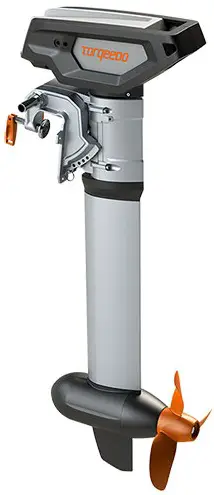
![]() This installation drawing is an addition to the original operating instructions. Read operating instructions before wiring.
This installation drawing is an addition to the original operating instructions. Read operating instructions before wiring.
Power cable connection
 Positive power cable
- Negative power cable
- Positive charging cable
- Negative charging cable
 AC power cable
System ground connection
Use for boats without common point for grounding.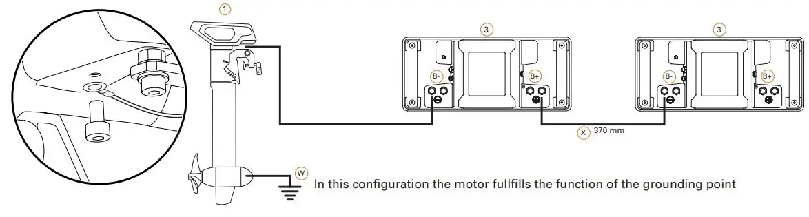
- 25 mm2 grounding cable
Use for boats with common point for grounding.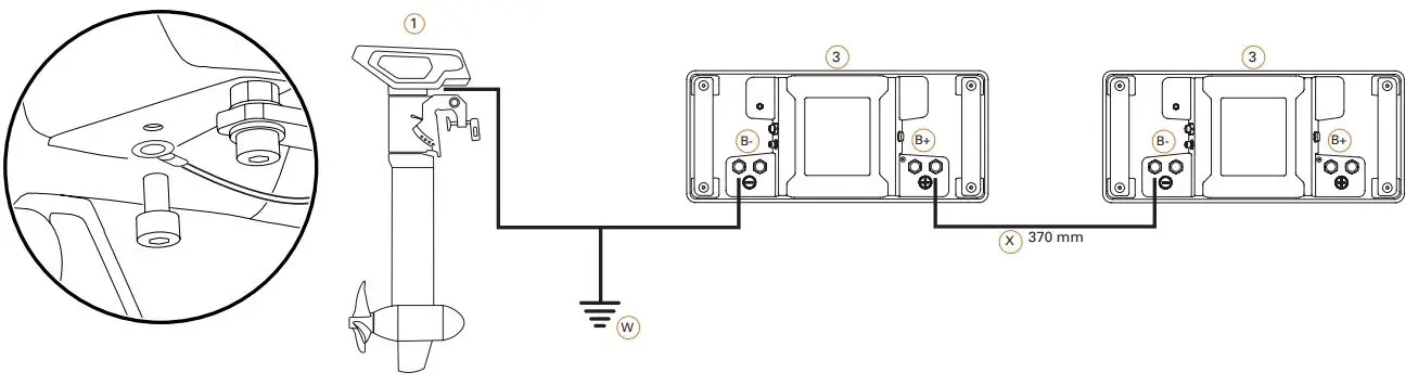
- 25 mm² grounding cable
 In case the charger is permanently installed in the boat, the charger housing or its AC PE and battery minus pole must be connected to the common grounding point. The AC connection requires specialist knowledge and may only be carried out by qualified personnel.
If necessary, have the planning and installation carried out by a specialist.
NOTE! To charge the batteries in the boat, a land connection in the boat with galvanic isolator or isolation transformer is required according to applicable national requirements (e.g. DIN EN ISO 13297, ABYC E-11).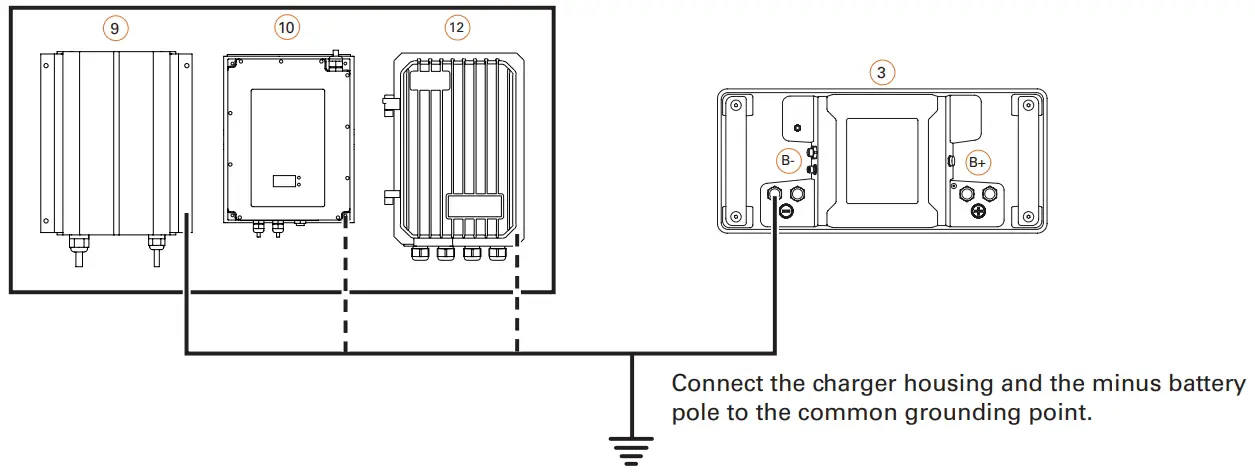
- 25 mm2 grounding cable
Data cable connection
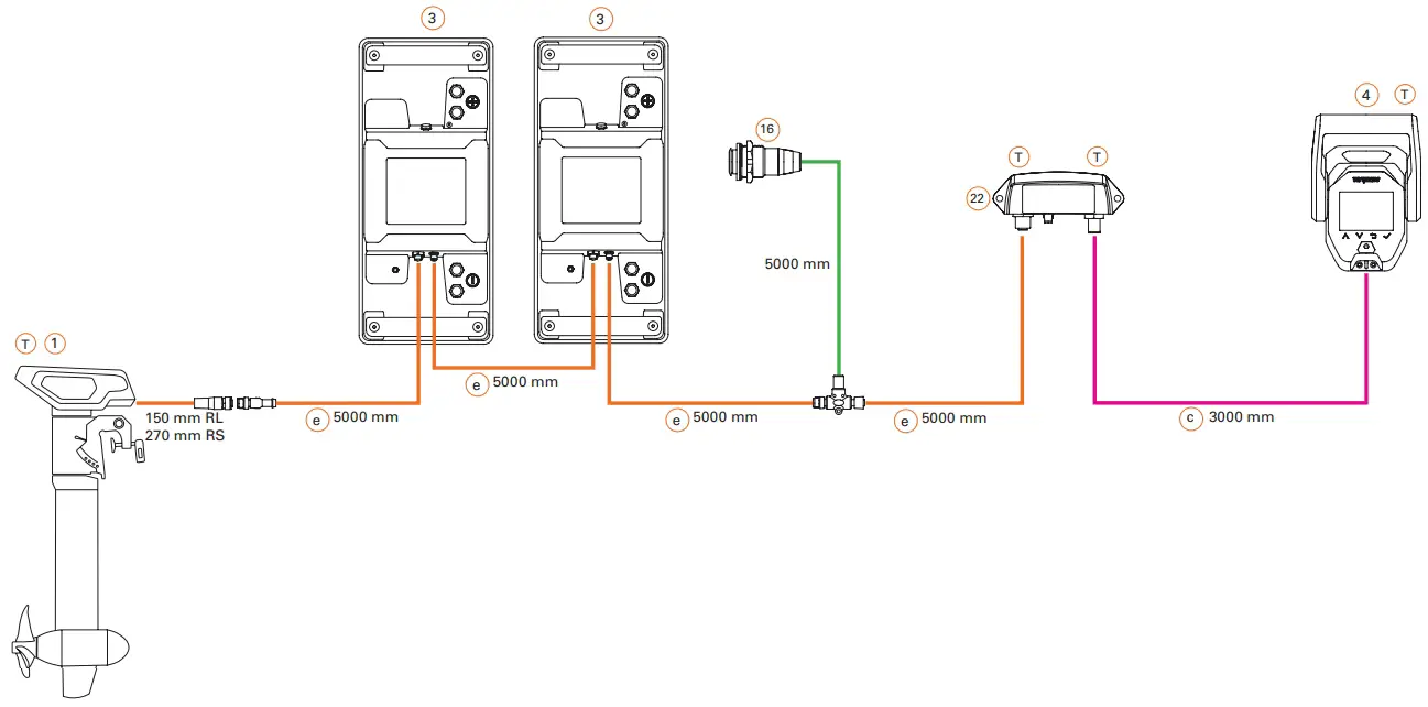
 8 pin data cable
- 5 pin data cable
 4 pin data cable
- Backbone TorqLink, 8 pin data cable
- Backbone 5 pin data cable
- T Bus system termination resistor
Bill of material/Legend/Information
Pos. | Item number | Name | Remarks |
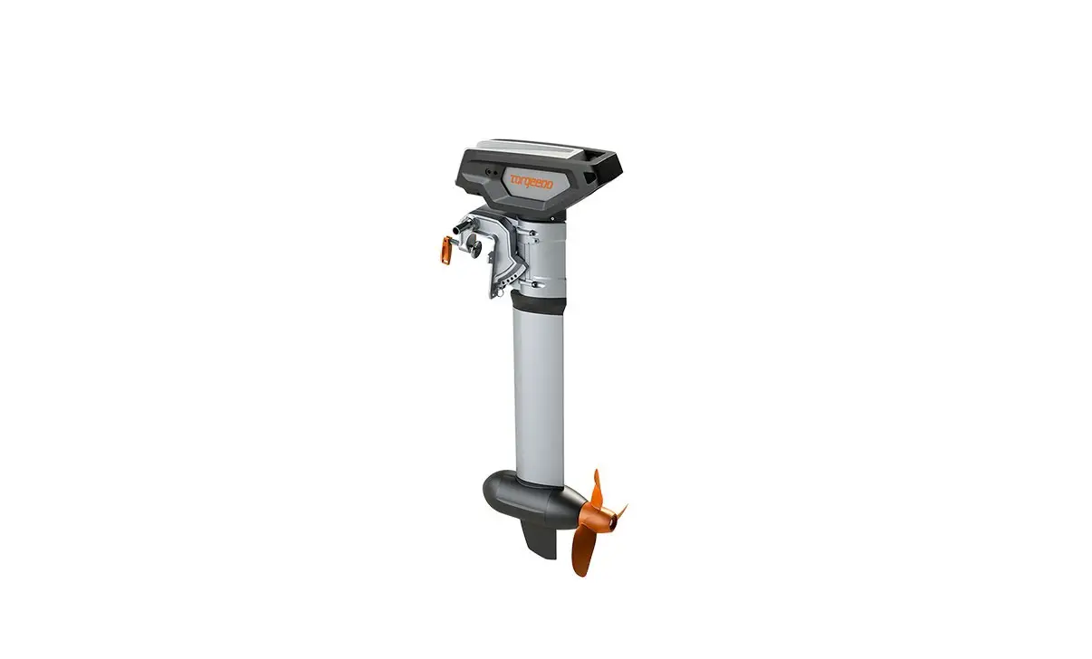
| 1 | 1262-10 1263-10 | Cruise 6.0 R | |
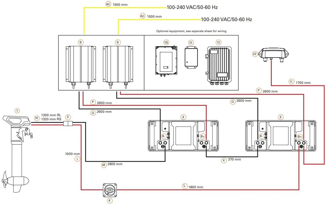
| H, I, K, L, M | Cable set with battery switch | See picture for cable length | |
| 2 | Power connector | max. 175 A | |
| e | Backbone cable 5-pin | 5000 mm | |
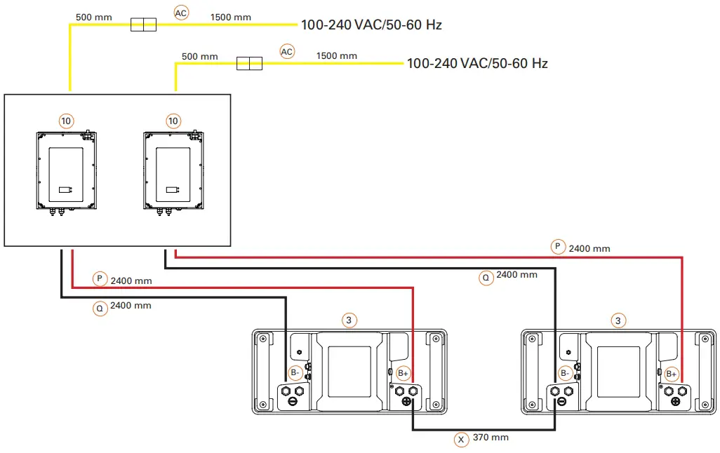
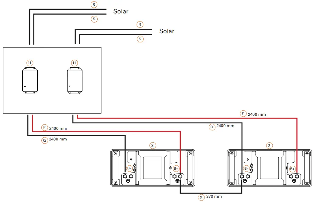
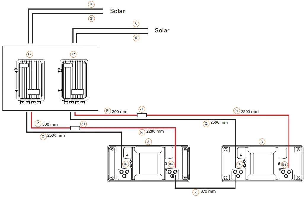
| X | Parallel bridge cable | 370 mm, 25 mm2 | |
| 3 | 2106-00 | Power 24-3500 | Select TorqLink-Battery in throttle menu! Due to voltagelevel above 50 V, take care of your local requirements |
| e | Backbone cable 5-pin | 5000 mm | |
| W | System ground | min. 25 mm2, not included | |
| 16 | 2304-00 | On/Off Switch Power 24-3500 with cable | 5000 mm |
| 4 | 1976-00 | TorqLink Throttle | |
| c | Backbone TorqLink cable 8-pin | 3000 mm | |
| 9 | 2206-20; 2206-30; 2206-40 | Charger Power 24-3500 | 350 W |
| P | + DC charge cable | 2600 mm; Do not extend! | |
| Q | – DC charge cable | 2600 mm; Do not extend! | |
| B+ | + Battery pole | ||
| B- | – Battery pole | ||
| AC | AC power cable | 1500 mm | |
| 2217-00 | TorqLink gateway set | ||
| 22 | 000-00858 | Gateway | |
| U | Gateway Power cable | 1700 mm | |
| f | Adapter T-Cable 5-pin | 200 mm | |
| e | Backbone cable 5-pin | 5000 mm | |
| 13 | 000-00876 | TorqLink Terminator | Bus termination resistor |
| 18 | On/Off switch with cable | 2000 mm | |
| Optional equipment | |||
| 10 | 2210-00 | Fast Charger Power 24-3500 | 1700 W |
| P | + DC charge cable | 2400 mm; Do not extend! | |
| Q | – DC charge cable | 2400 mm; Do not extend! | |
| B+ | + Battery pole | ||
| B- | – Battery pole | ||
| AC | AC power cable | 2000 mm | |
| 11 | 2207-00 | Solar charge controller Power 24-3500 | |
| P | + Charge cable | 1000 mm | |
| Q | – Charge cable | 1000 mm | |
| R | + Input solar cable | 1000 mm | |
| S | – Input solar cable | 1000 mm | |
| 12 | 2211-00 | Fast solar charge controller Power 24-3500 | |
| P | + Charge cable | 300 mm | |
| P1 | + Charge cable | 2200 mm | |
| Q | – Charge cable | 2500 mm | |
| 21 | Fuse | 100 A/58 V | |
| R | + Input solar cable | not included | |
| S | – Input solar cable | not included | |
Connect the cruise motor and terminator to each end of the backbone. The TorqLink bus system requires a terminator (terminating resistor) at both ends of the backbone in order to function correctly. One of the terminators is located in the „Terminator Single“, „Terminator Twin“, „Throttle 1918-00“, „ Throttle 1976-00“ , the other is built into the cruise motor. Therefore, when installing, make sure that the components „Terminator“ and „Cruise motor“ are each connected to one end of the backbone. The connection position of the remaining components on the backbone can be freely selected.
Keep the following points in mind when planning:
- An earthing point is required for your Torqeedo system. Take into account the connection and the cables required for this in your planning. The required cable cross-sections can be found in the section Tools, equipment and material.
- First determine and plan the installation positions of all components.
- Measure the required length of the TorqLink backbone.
- Measure the lengths of all required stub lines (cable connection between component and TorqLink backbone).
- When planning, please note that TorqLink drop cables must not be extended. If necessary, plan the TorqLink backbone so that the components can be connected through the TorqLink drop cable without an extension. If necessary, extend the TorqLink backbone to connect a component that is far away; you can find corresponding extensions in our accessories catalogue.
- Cables must be fixed every 400 mm, plan attachment material. In places where fastening is not possible, a scuff guard must be fitted.
- Openly laid cables (e.g. inflatable boat) must be protected with chafing protection, plan sufficient material.
- When planning, please note not to bundle power cables with data or antenna cables (e.g. radios) for other loads.
- Observe the minimum bending radius of the cables when planning.
- If a second earthed onboard power system is available, ensure that both systems use a common earthing point.
- Live parts must be fitted or installed with protection against accidental contact; the necessary installation space must be taken into account during the planning stage.
- Always connect batteries as the last component to the system to avoid short circuits and voltage peaks.
- Do not extend drop cables, extend backbone if necessary.
- Protect plugs and contacts against contamination before installing them.
- Do not pull at the cables.
- Do not twist cables.
- Do not install cables in permanently wet areas such as bilges.
- Install cables free of chafing and not around sharp edges, if necessary, attach chafing protection.
- Maintain bending limits.
- Install plug connections free of tension and load.
Observe the minimum bending radius when laying all cables: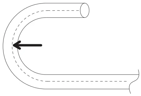
| Torqeedo data cable | 8 x diameter |
| Torqeedo power cable | 8 x diameter |
| Earth cable | see cable manufacturer’s specifications |
| Other power cables | see cable manufacturer’s specifications |
Power cable connection
- Positive power cable
- Negative power cable
- Positive charging cable
- Negative charging cable
- AC power cable