V-TAC 80133970 Set of 10KW Hybrid Inverter
BATTERY STORAGE
TECHNICAL DATA
| Battery type | LFP |
| Rated capacity of battery pack | 100Ah |
| Rated voltage of battery pack | 51.2V |
| Maximum charging voltage | 57.6V |
| Minimum discharge voltage | 40V |
| Rated charge/discharge current | 100A |
| Maximum charge/discharge current | 120A |
| Charging temperature range | 0 to +45°C |
| Discharge temperature range | -20°C to +50°C |
| Depth of discharge | >80% |
| Discharge magnification | <1C |
| Self-discharge (25°C) | <3%/Month |
| Cycle life | >5000 times(<0.5C ) |
| Interactive mode (APP) | LCD+Button+Bluetooth |
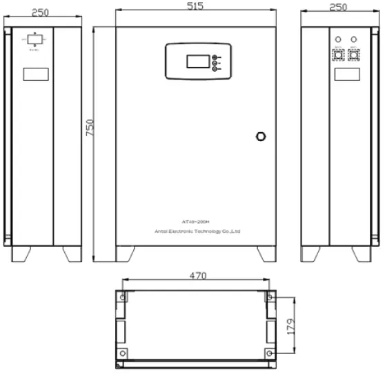
| Dimension | 700*515*250mm (Error±2mm) |
| Weight | About 65KG |
| Compatible with Solar Inverter [VT-66036103, VT-6605103, VT-12040] | |
INTRODUCTION
Thank you for selecting and buying V-TAC Product. V-TAC will serve you the best.
Please read these instructions carefully & keep this user manual handy for future reference. If you have any another query, please contact our dealer or local vendor from whom you have purchased the product. They are trained and ready to serve you at the best.
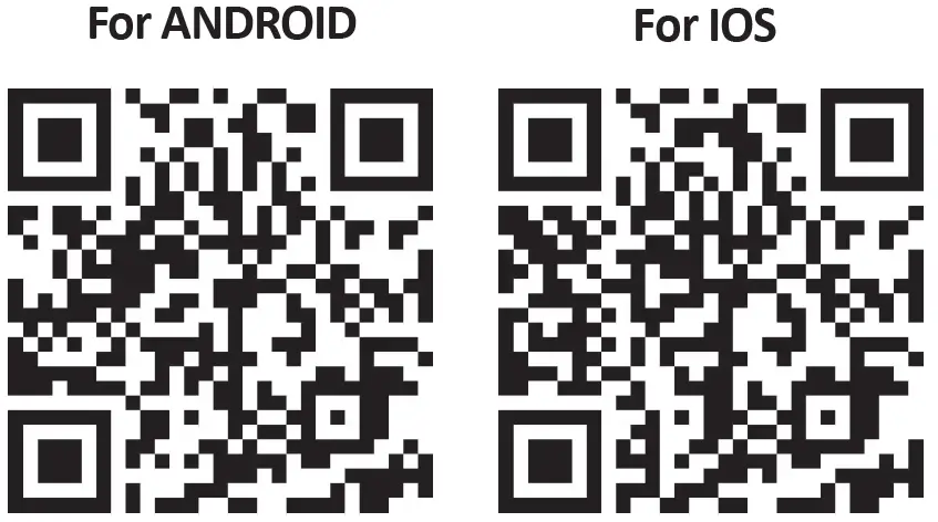
Multi-Language Manual QR CODE
Please scan the QR code to access the manual in multiple languages.

IN CASE OF ANY QUERY/ISSUE WITH THE PRODUCT, PLEASE REACH OUT TO US AT: [email protected] FOR MORE PRODUCTS RANGE, INQUIRY PLEASE CONTACT OUR DISTRIBUTOR OR NEAREST DEALERS. V-TAC EUROPE LTD. BULGARIA, PLOVDIV 4000, BUL.L.KARAVELOW 9B
WARNING
- Please make sure to turn off the power before starting the installation.
- Installation must be performed by a qualified electrician.
 This marking indicates that this product should not be disposed of with other household wastes.
 Caution, risk of electric shock.

CONTROL PANEL
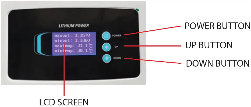
HUMAN-COMPUTER INTERACTION CONTENT
| Project | Function | Remark |
| Button | POWER | When Powered on: 1. Short press: invalid 2. Long press (press for 4~6 seconds and release): power off When powered off: 1. Short press: invalid 2. Long press (press for 4~6 seconds and release ): turn on |
| UP | Page up | |
| DOWN | Page down | |
| Switch | DC OUTPUT | Use the key to open the front panel before switching on and off |
HUMAN-COMPUTER INTERACTION CONTENT
| Project | Function |
| LCD | There are 6 display interfaces in total: 1. Main interface information (voltage/current/SOC/status code); 2. Secondary main interface information (maximum and minimum cell voltage/maximum and minimum temperature); 3. Display 1~4cell voltage; 4. Display 5~8cell voltage; 5. Display 9~12cell voltage; |
| Error code | E11: Level 1 alarm of module equipment failure |
| E12: Module equipment failure secondary alarm | |
| E21: Level 1 alarm of module communication abnormality | |
| E22: Module communication abnormality secondary alarm | |
| E31: Module address is abnormal level 1 alarm | |
| E32: Module Address Abnormal Level 2 Alarm | |
| E41: Module balancing abnormal level 1 alarm | |
| E42: Module balance abnormal secondary alarm | |
| E51: Module total voltage overvoltage level 1 alarm | |
| E52: Module total voltage overvoltage secondary alarm | |
| E61: Level 1 alarm of module total voltage under voltage | |
| E62: Second-level alarm of module total voltage under voltage | |
| E71: Module charging overcurrent level 1 alarm | |
| E72: Module charging overcurrent secondary alarm | |
| E81: Module discharge overcurrent level 1 alarm | |
| E82: Module discharge overcurrent secondary alarm | |
| E83: Module discharge load short circuit (serious) | |
| E91: Single battery overvoltage level 1 alarm | |
| E92: Single battery overvoltage secondary alarm | |
| E101: Single battery under voltage level 1 alarm | |
| E102: Single battery under voltage secondary alarm | |
| E111: Module battery high temperature level 1 alarm | |
| E112: Module battery high temperature secondary alarm | |
| E121: Module battery low temperature level 1 alarm | |
| E122: Module battery low temperature secondary alarm |
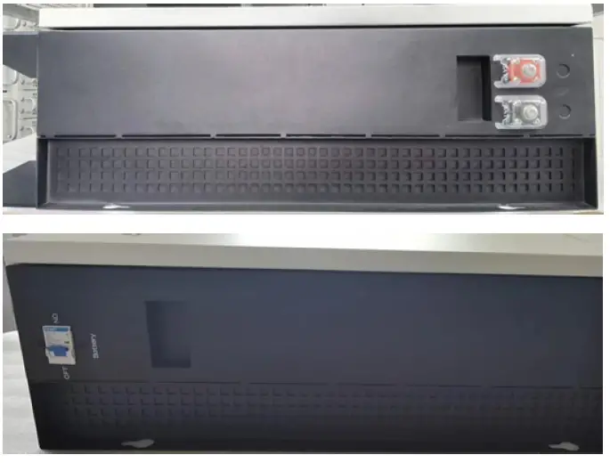
INTERFACE DEFINITION
| Port | Port type | NO | Signal name | Remark |
| Battery interface | BAT | 1 | BAT+ | Battery positive output interface |
| 2 | BAT- | Battery negative output interface | ||
| Battery output switch | Battery | – | Battery | Battery output switch (control positive) |
INSTALLATION
- Refer to the figure below to install the battery module, the fixing feet are on the ground, the module body is fixed on the wall, and the screws are 4~6mm combination screws. The reference tightening torque is 35 N.m. (unit mm)
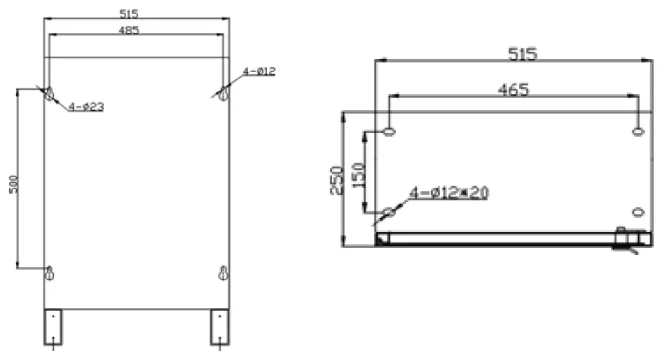
- Check whether the battery module is firm and safe. (Avoid damp, rain, and direct sunlight as much as possible)
APP INSTALLATION
- Step 1: Scan the given QR code to download App then install the app.
- Step 2: After the installation is complete, open the phone settings – application settings authorization management, and authorize the Bluetooth and positioning of this APP.
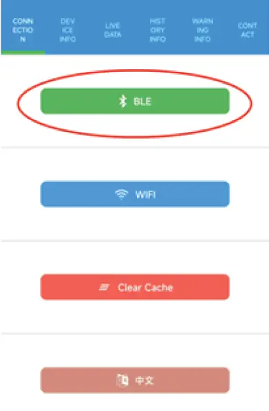
- Step 3: Open the software and click “BLE” to connect to Bluetooth
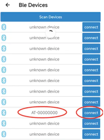
- Step 4: Click “Scan Devices” to scan the machine, find the device starting with “AT” and Click “connect” to connect.t
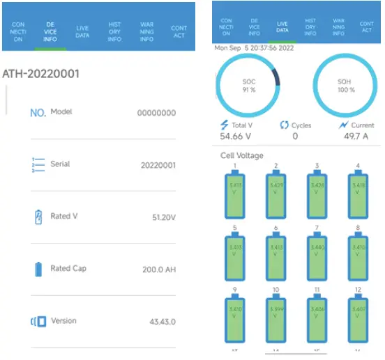
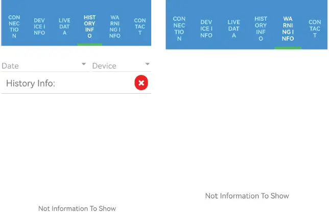
- Step 5: Artier successfully pairing the device with the app, you can start reading the relevant data, including “CONNECTION, DEVICE INFO, LIVE DATA, HISTORY INFO, WARNING INFO, CONTACT” to switch (See the below pic).