TRIDONIC lux CONTROL Basic DIM ILD G2 Programmer Instruction Manual

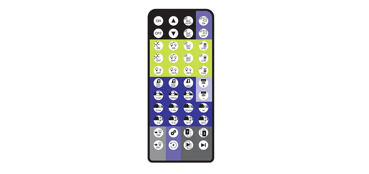
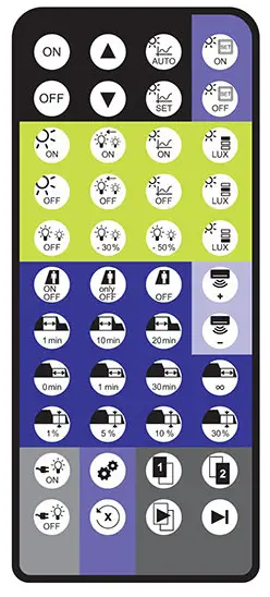
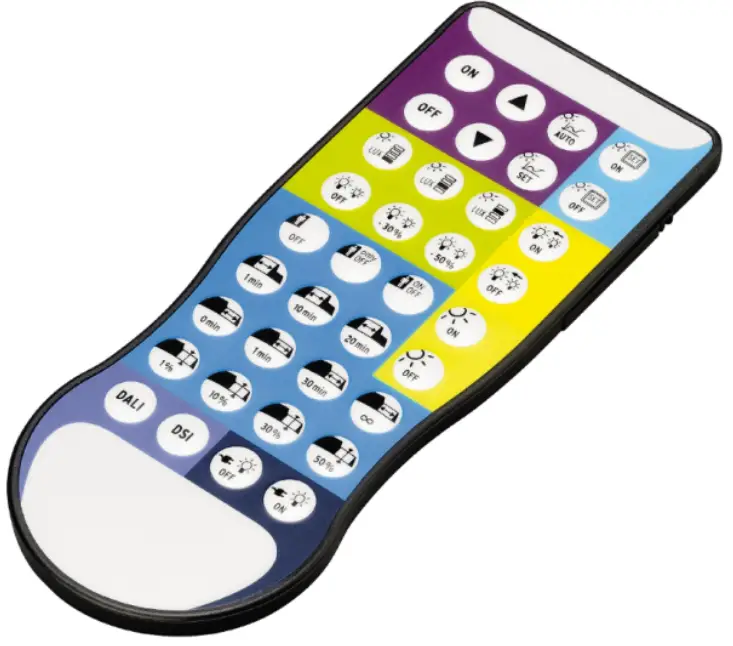
Operating the basic DIM ILD Programmer

 NOTICE
Some functions of the basic DIM ILD Programmer can also be used with Tridonic sensors. A summary table can be found at other the end of this document under “Operating basic DIM ILD with other sensors
basic DIM ILD Programmer can be used to set parameters for the basic DIM ILD module. The following parameters are available:
Basic functions
| Icon | Designation | Description |
 | ON | Switch luminaires on |
 | OFF | Increase current dimming leve |
 | Dim up | Decrease current dimming level |
 | Dim down | Change to automatic mode Dimming is started |
 | Automatic mode | Store the brightness level currently measured by the sensor as target value for constant light |
 | Set current light level | Store the brightness level currently measured by the sensor as target value for constant light control |
Push to make switch functions
The abbreviation PTM stands for “push to make switch”.
| Icon | Designation | Description |
 | PTM Set ON | PTM Set ON Enable storage of target level via push to make switch input double clicking the push to make switch at the push to make switch input allows storing the brightness level currently measured by the sensor as target level for constant light control |
 | PTM Set OFF | Disable storage of target level via push to make switch input storing the target level via push to make switch input is not possible |
Constant light control settings
NOTICE
The light levels indicated are based on a standard room situation and may differ from the levels actually measured in the task area.
- Try all three light levels and select the one most suitable!
| Icon | Designation | Description |
 | Light level | low Set ambient light control to a level of approx. 150 lx |
 | Light level middle | Set ambient light control to a level of approx. 300 lx |
 | Light level high | Set ambient light control to a level of approx. 500 lx |
Offset settings
Use the Offset settings to specify and define in detail differences in brightness between the two channels.
| Icon | Designation | Description |
 | Offset Value 0 % | Set the difference in brightness between channel 2 and channel 1 to 0 % |
 | Offset Value -30 % | Set the difference in brightness between channel 2 and channel 1 to -30 % |
 | Offset Value -50 % | Set the difference in brightness between channel 2 and channel 1 to -50 % |
 | Offset Mode Converging | Reduce the difference in brightness between channel 2 and channel 1 at increased or reduced dimming level. For example: at an offset value of -30 %, one channel’s dimming level is 30 % lower than the other’s (e.g |
 | Offset Mode Fixed | Maintain the difference in brightness between channel 2 and channel 1 at increased or reduced For example: at an offset value of -30 %, one channel’s dimming level is 30 % lower than the other’s (e.g. channel 2: 40 %; channel 1: 70 %). When dimmed up, channel 2 will remain at a level of 70 % as soon as channel 1 has reached the dimming level of 100 %. |
Bright Out settings
The Bright Out function defines how the ambient light control system will respond to additional illumination by sunlight or other light
| Icon | Designation | Description |
| Bright Out ON | Switch on Bright Out: if the measured light level exceeds 150 % of the target level for more than 10 minutes, the light is switched off. If the measured light level falls below 100% of the target level, the PHASED light is switched back on again. |
basicDIM ILD Programmer: Functions and Parameters | 12-2018 | en
| Bright Out OFF | Switch off Bright Out: The light remains switched on at all times, irrespective of the light level measured. |
Presence detection profile settings
The abbreviation P.I.R. stands for “passive infrared”. This function is used to control presence detection.
| Icon | Designation | Description |
 | P.I.R. inactive | Disable presence detection Run-on time is automatically set to “infinite” |
 | P.I.R. off only | Presence detection responds only to absence light must be switched on manually (push to make switch, remote control) if no persons are detected, light is switched off automatically Run-on time is au |
 | P.I.R. active | Enable presence detection light is switched on and off automatically based on the presence/absence of a person Run |
 | Time delay 1min | 1 minute after the last presence was detected, light is dimmed to Sec. Level |
 | Time delay 10min | n-on time to 10 minutes 10 minutes after the last presence was detected, light is dimmed to Sec. Level |
 | Time delay 20min | 20 minutes after the last presence was detected, light is dimmed to Sec. Level |
basicDIM ILD Programmer: Functions and Parameters | 12-2018 | en
 | If vacant 0min. | Set switch-off delay to 0 minutes light is switched off immediately after run-on time has expired |
 | If vacant 1min. | Set switch-off delay to 1 minute light is switched off 1 minute after run-on time has expired |
 | If vacant 30min. | Set switch-off delay to 30 minute light is switched off 30 minutes after run-on tim has |
 | If vacant continuous | Set switch-off delay to “infinite” (neverOFF) light is not switched off after |
 | Sec. Level 1% | Set the absence level to 1 % = dimming level to which the light is dimmed after the run-on time has expired |
 | Sec. Level 10% | Set the absence level to 10 % = dimming level to which the light is dimmed after the run-on time has expired; applies only if “if vacant” 0min |
 | Sec. Level 30% | Set the absence level to 30 % = dimming level to which the light is dimmed after the run-on time has expired; applies only if “if vacant” 0min |
 | Sec. Level 50% | Set the absence level to 50 % = dimming level to which the light is dimmed after the run-on time has expired; applies only if “if vacant” 0min |
basicDIM ILD Programmer: Functions and Parameters | 12-2018 | en
| Icon | Designation | Description |
 | DALI | Select DALI Broadcast as interface operating mode |
 | DSI | Select DSI as interface operating mode |
| Icon | Designation | Description |
 | Power Up ON | luminaire is switched on again after a mains break |
 | Power off | luminaire is switched on again after a mains break |
Operating basic DIM ILD with other sensors
Basic functions
| Icon | Designation | DALI MSensor 02 / MSensor 5DPI 14 | basicDIM DGC | SMART Sensor 5-10DPI 19f | DSI PTM |
 | ON |  | | | |
| OFF | | | | |
 | Dim up | | | | |
 | Dim down | | | | |
 | Automatic mode | | | | |
 | Set current light level | | | | |
Push to make switch functions
The abbreviation PTM stands for “push to make switch”
| Icon | Designation | DALI MSensor 02 / MSensor 5DPI 14 | basicDIM DGC | SMART Sensor 5-10DPI 19fe | DSI PTM |
 | PTM Set ON | | | | |
 | PTM Set OFF | | | | |
Constant light control settings
| Icon | Designation | DALI MSensor 02 / | basicDIM DGC | SMART Sensor 5-10DPI 19fe | DSI-SMART PTM |
 | Light level low | | | | |
 | Light level middle | | | | |
 | Light High | | | | |
Offset settings
| Icon | Designation | DALI MSensor 02 / MSensor 5DPI 14 | basicDIM DGC | SMART Sensor 5-10DPI 19fe | DSI-SMART PTM |
| Offset Value 0 % | | | | |
 | Offset Value -30 % | | | | |
 | Offset Value -50 % | | | | |
| Offset Mode Converging | | | | |
 | Offset Mode Fixed | | | | |
Bright Out settings
| Icon | Designation | DALI MSensor 02 / MSensor 5DPI 14 | basicDIM DGC | SMART Sensor 5-10DPI 19fe | PTM |
 | Bright Out ON | | | | |
 | Bright Out OFF | | | | |
Presence detection profile settings
| Icon | Designation | DALI MSensor 02 / MSensor 5DPI 14 | basicDIM DGC | SMART Sensor 5-10DPI 19fe | PTM |
 | P.I.R. inactive | | | | |
 | P.I.R. off only | | | | |
 | P.I.R. active | | | | |
 | Time delay 1min. | | | | |
 | Time delay 10min. | | | | |
 | 20min | | | | |
 | If vacant 0min | | | | |
 | If vacant 1min. | | | | |
 | If vacant 30min. | | | | |
 | If vacant continuous | | | | |
 | Sec. Level 1% | | | | |
 | Sec. Level 10% | | | | |
 | Sec. Level 30% | | | | |
 | Sec. Level 50% | | | | |
Interface operating mode settings
| Icon | Designation | DALI MSensor 02 / MSensor 5DPI 14 | basicDIM DGC | SMART Sensor 5-10DPI 19fe | PTM |
 | DALI | | | | |
 | DSI | | | | |
Return of power settings
| Icon | Designation | DALI MSensor 02 / MSensor | basicDIM | SMART Sensor 5-10DPI 19fe | DSI-SMART PTM |
 | Power Up ON | | | | |
 | Power Up OFF | | | | |

Download manual
Here you can download full pdf version of manual, it may contain additional safety instructions, warranty information, FCC rules, etc.
To access the pdf donwload links, solve the captcha.