![]()
USER MANUAL
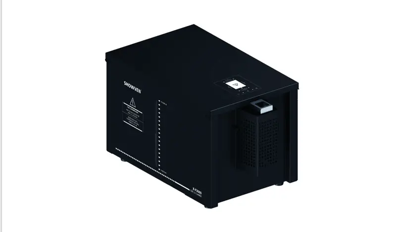
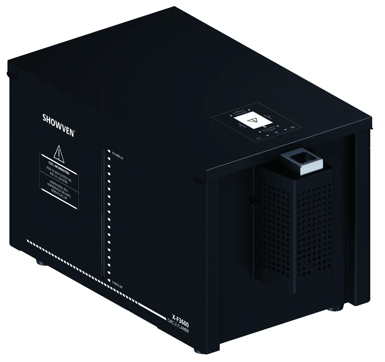
CIRCLE FLAMER X-F3600
V1.2
Showven Technologies Co.,Ltd.
CIRCLE FLAMER X-F3600
USER MANUAL
★ Please read this manual carefully before operating this product.
★ Warranty card attached in the manual, please keep it well.
▲WARNING
- Unauthorized repair are prohibited, it may cause serious incident.
- Make sure power supply inconsistent with the rated voltage of the equipment, and the socket must well grounded. Unplug and turn off the machine when not use.
- Before connect the power cable, communication DMX cable should well connected and ensure the command keep at firing OFF status. And safety lock stay at test mode.
- The device can only be placed horizontally. Safety distances are marked on the device (at least 15m in all projection directions, at least 5m to the other sides of the device).
- After turning on the device, no person allows to stay in the danger area. Ensure all persons that are part of the show be informed about the safety distance, risks and functions of the device.
- Always have a CO2 fire extinguisher and an extinguishing blanket in case of needed.
- If there be any doubt as to the safety operation of the device in any circumstances, the device should be taken out of service immediately. Be sure the device is in good operating condition before use. If fail to fire correctly, immediately shut down and check it accordingly
- Be sure to use high quality flame fluid, otherwise, it is easily lead to failure or danger. Be careful when refill the flame fluid tank. Please keep flame fluid away from heat source, sparks, fire or other possibilities of ignition. Do not smoke!
- The operator responsible for the control of Circle Flamer must always have a clear view of the device, so that he/she can stop the show immediately when there is danger. The main AC power switch should near operator. So that operator can turn off the power of all devices in case of abnormal.
- The device shall not be altered and applied to other use purposes
- Notes for use of Battery power supply: CIRCLE FLAMER with stable internal circuit design, please support X-F3600 with battery voltage higher than 12V. The driving speed of motor won’t change because of the decrease of battery power supply. Battery options: 12V lead-acid battery (above 30AH, with more than 24h standby). For Lithium battery, please use battery with output above 30A. Socket type: NEUTRIK-NL4FX, 4 pin sound coupliers (1+ connect 12V anode, 1- connect 12V cathode). Connecting power cables should above 14AWG.
- Nozzle Protection Cover of X-F3600 should be removed before power-on, otherwise, the rotating mechanism of the equipment will be damaged. The Nozzle Protection Cover is only used during transportation.
- The firing nozzle of X-F3600 is strictly forbidden to rotate over ±90° manually in case of power-off, otherwise, the rotating mechanism of the equipment will be damaged.
▲Foreword
Thanks for choosing SHOWVEN CIRCLE FLAMER X-F3600. Please read following manual carefully and completely before operating this product. Operate according to instructions is very important for safety, and can elongate the service life of the machine.
Strictly follow the instruction in the manual when operate Circle flamer X-F3600. If you have any doubts, please contact SHOWVEN technologies Co., Ltd by [email protected].
We assume the person who use or come in contact with the device are familiar with how the device should be handled. This includes proper use, maintenance and repair of the machine as defined in this user manual.
Disclaimers:
SHOWVEN technologies Co., Ltd excludes liability for unsafe situations, accidents, and damages resulting from:
- Ignoring warnings or regulations as shown on circle flamer or this manual.
- Use for other applications or circumstances other than those indicated herein.
- Changes to the circle flamer, including use of non-original spare parts.
- Removed safety cover without authorization from SHOWVEN.
- Use this machine by unqualified or untrained personnel.
- Improper use of machine.
▲Functional Characteristics
- Compact pumping system ensure compact size of machine.
- Double electromagnetic valves design for additional safety.
- Tilt protection, the tilt sensor will be activated when machine slant Over 45°.
- Unique safety lock design, device can’t firing when locked, avoid spurious triggering.
- Intelligent control system: pressure monitoring, safety warning, no fuel alarming, system failure warning etc.
- High-performance nozzle, reliable and durable.
- High-accuracy rotating head driving and controlling system, allows for fast and precise flame bursts.
- Strengthened and rustproof metal panel, water-proof design.
- Neutrik PowerCON TRUE1 and DMX socket.
- Standard battery connector configuration, support 12V battery power supply.
- Fitted with fireworks igniter signal port, can be triggered by fireworks igniter.
- Flame effects up to 8-10m (no wind), with maximum rotation of 3 cycles.
- As much as 160 preset flame sequences are available. It is easier and stable to running the CIRCLE FLAMER when controlled by SHOWVEN original host controller ZK6200/ZK6300.
▲Technical Specifications
| MODEL | Circle Flamer X-F3600 |
| Rotation Mode Switch | FULL CIRCLE MODE / HALF CIRCLE MODE |
| Dimension | 640 x 360 x 370mm |
| Input | AC100-240V,50-60Hz |
| Work power | 380W |
| Interface | Double DMX Interface; 9V-60V Fireworks igniter signal |
| Control | Standard DMX |
| Effect Maximum Height | 8-10m (no wind) |
| Effect Angles | 1080° (up to 3 cycles) |
| Fuel | ISOPROPANOL, ISOPAR G,H,L,M, BIOETHANOL |
| Fuel Bottle Capacity | 10L |
| Weight (no fuel) | 30Kg |
| Fuel Consumption Rate | 60ml/s |
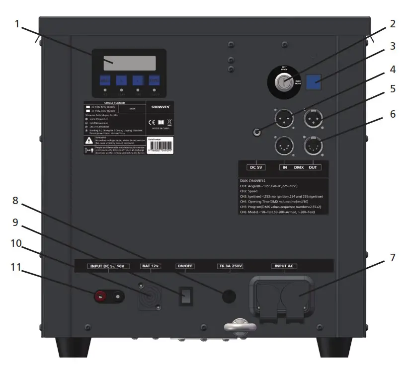
▲Structure of Circle Flamer
1. Nozzle Protection Cover
2. Firing Nozzle
3. Top Panel
4. Fuel Bottle Area
5. Control Panel
6. Safety Loop
• Connection dimension diagram of bottom bracket of the flamer
▲Overview of Control Panel
1. LCD screen operate panel
2. Safety Lock
3. Indicator Light
4. DC 5V output
5. 3-pin DMX socket
6. 5-pin DMX socket
7. 110V/220V Power socket
8. Fuse
9. ON/OFF switch
10. 12V Battery socket
11. DC 9V-60V fireworks igniter signal port
▲Operation Panel
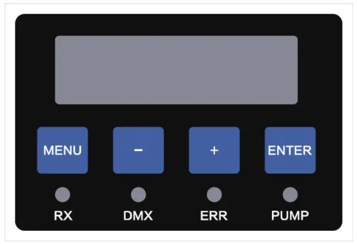
1. LED Display Area
RX: Radio receiving (reserved);
DMX: DMX signal. Flash means DMX signal available, otherwise no DMX signal;
ERR: Light on when there is an error;
PUMP: Light on when pump is running.
2. Button Funtions:
MENU: Switch interface to setup parameter;
+: Parameter Up;
-: Parameter Down;
ENTER: Confirm and save parameters (screen will flash when parameters saved);
Note: screen display will switch to main interface if don’t press button for a long time.
3. Welcome Interface
First Line: Product model and software version number;
Second Line: Equipment factory number.

4. Main Interface
First Line: Rotation Mode(Full Cycle Mode(360) or Half Cycle Mode(180) );DMX address;
Second Line: Pressure100 (e.g. 100=10bar); V: 13.6 means internal voltage is 13.6V.

5. Alert Message
| Alert Message | Explanation |
| EO System Lock | Safety lock located at TEST MODE. |
| El Pressure Err | Pressuriser for about 13s, pressure value failed to reach 100%, system will report E1. Possible fault: No fuel, pump failure, pipeline problem etc. |
| E2 P Relief Err | Pipeline can’t release pressure leads to pressure relief error. Possible fault: pressure release valve failure, pipeline problem or control system problem etc. |
| E3 Motor Err | Motor fault Possible fault: swiveling nozzle stuck, motor failure etc. |
| E4 Ext Ignition | When Ext Ignite is ON, device will pressuriser automatically when switch safety lock to USER MODE; decompression when switch to TEST MODE. 9V-60V fireworks ignitor signal will trigger related firing sequences. |
| E5 Voltage Err | Battery voltage >15V or <10V for continuous 5s, machine stops running. Possible fault: the battery is low. |
| E6 Tip Err | if the machine slant over 45° , it stops running, system will report E6. |
| E7 Factory Mode | DMX signal blocked in factory mode. |
6. Interface setup
Press “MENU” to switch through setup menu.
| Menu | Range | Explanation |
| Set DMX Address | 1-512 | DMX address setup |
| Set Rotation Mode | Full Cycle Mode (360) / Half Cycle Mode (180) | Switch Cycle Mode |
| Angle Limit Note: Angle limit activates under half-cycle mode | MIN: NO.1-N0.15 MAX: Na1-NO.15 | Restrict nozzle rotate angles: Set by “+” and “-“, and confirm by “ENTER” |
7. Advanced Interface
Press “MENU” 3s enter advanced interface, press “MENU” to switch interface, press “MENU” 3s can back to main interface.
| Items | Contents | Description |
| Drive Test | OFF / Motor/ Pump / Igniter / Relief Valve / Jet Valve | |
| 1.Motor | Swiveling and stop at target angle. | |
| 2.Pump | Pump running 1s, if pressure reached the target value, the pump will not running. | |
| 3.Igniter | Ignite 1s | |
| 4.Relief Valve | Release pressure 1s | |
| 5.Jet Valve | Safety lock located at user mode, release pressure for 5s, open jet valve and close to check the working status of jet valve. | |
| Ext Ignite | ON /OFF | Trigger through 5-60V fireworks ignitor signal |
| Set Ext Sequence | Full Cycle Mode: 1-94 Half Cycle Mode: 1-70 | Preset sequence triggered by fireworks ignitor |
| Language | Chinese / English | Language switch |
| Mode Select | Factory Mode / Normal Mode | Factory mode is for test in factory only |
| Tip Setting | ON / OFF | Turn-ON/OFF tip-over function |
| Reset Parameter | YES / NO | Reset default parameter settings |
▲Operation Instructions
1. Direction explanation
Please read the safety distance print on the top panel of CIRCLE FLAMER carefully.
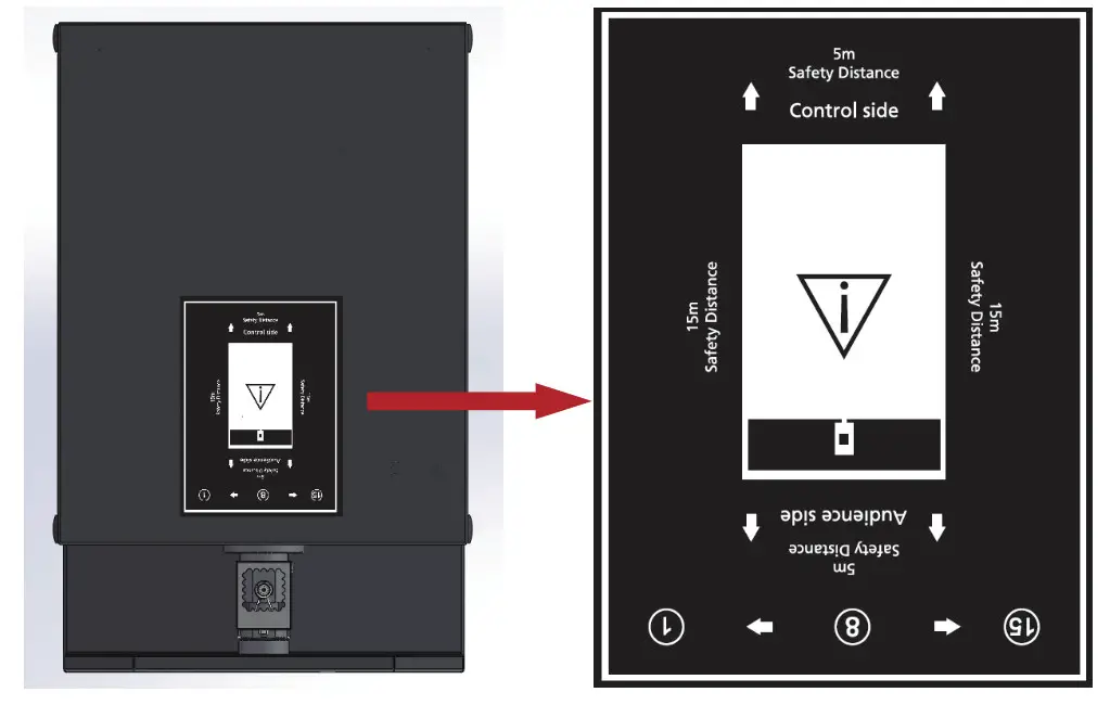
(1) 1 to 15 is the firing angle when Circle flamer running in half cycle mode.
(2) AMGS is the firing direction when running in full cycle mode, A is downward, M is upward, G is left side, S is right side.
For more detail please refer to angle definition in under full cycle mode.
(3) Audience side and control side are indicated in above picture.
(4) Safety distances for CIRCLE FLAMER are indicated in above picture. At least 15m in all projection directions, at least 5m to the other sides of the device.
Note: in order to indicate correct direction, please place the top panel correctly.
2. Quick Operation Sheet
Immediately upon receiving the machine, carefully unpack the carton, check the machine received in good condition. Ensure safety operation of machine, please do following below operation procedures when operate CIRCLE FLAMER.
| Operation step | Schematic diagram and explanation | Explanation |
| 1. Installation | The device can only be placed horizontally, if placed on truss, please locked with extra safety ropes, Remove nozzle protection cover if it exists. | |
| 2. Locate safety lock at TEST MODE | 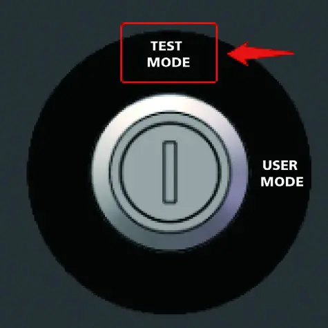 | Before operate machine please locate safety lock at TEST MODE. TEST MODE: operator can test the rotate of nozzle, but the fuel ejection function disabled, so there is no fuel eject and flames. USER MODE: the device can generate flames normally. Please strictly follow the safety distance requirement, remove all human, animal or flammable objects in the danger area. |
| 3. Fueling | 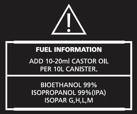 | Please fueling with high quality fuel according to requirement of this manual. |
| 4. Power and DMX cable connection |  | Two kind of power supply optional: 1. 110V/220V main power supply 2. 12V battery power supply |
| 5. Switch ON the machine |  | Please confirm safety lock located at TEST MODE before switch on the POWER ON/OFF. |
| 6. Set DMX address |  | CIRCLE FLAMER occupy 6 channels. Detail information please refer to the table of page18. |
| 7. Pressuriser |  | Host controller: Press”pre-heat” button (light on). DMX console: switch DMX value of channel 6 to 50-200. |
| 8. Check device status in TEST MODE | 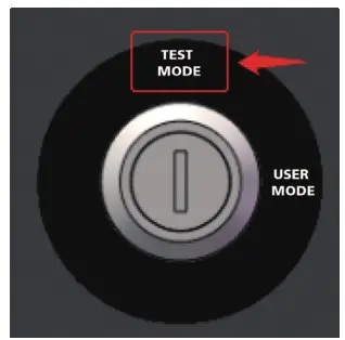 | Reconfirm safety lock located at TEST MODE before test. In this status, the nozzle will rotate, and igniter will activated, but there is no flame. When use DMX console to test the sequence, suggest to set CH1 at 128, so that nozzle stay at straight-up position after each sequence. |
| 9. Pressure Relief |  | Host controller: Press “pre-heat” key (light off). DMX console: switch DMX value of channel 6 to 0-49/201-255. |
| 10.Switch safety lock to USER MODE | 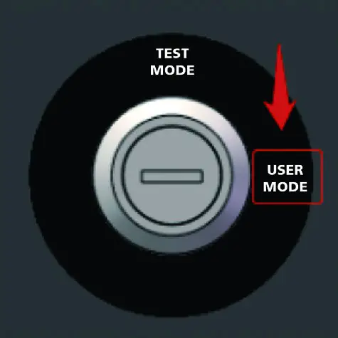 | Before switch to USER MODE, Please strictly follow the safety distance requirement, remove all human, animal or flammable objects in the danger area. |
| 11. Pressuriser |  | Host controller: Press”pre-heat” button (light on). DMX console: switch DMX value of channel 6 to 50-200. |
| 12. Firing |  | Set firing sequence Host controller: Press “FIRING” key. DMX console: switch DMX value of channel 3 to 254-255. |
| 13. Pressure Relief |  | Relief pressure when show finished or CIRCLE FLAMER not use for a long period. Host controller: Press “pre-heat” key (light off). DMX console: switch DMX value of channel 6 to 0-49/201-255. |
| 14. Switch safety lock to TEST MODE | 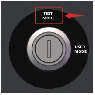 | Guarantee safety use for next time. |
| 15. Power off | | Power off CIRCLE FLAMER, tear down power cable and DMX cable, pack up the device when it is cooled down. |
3. Full Cycle Mode
(1)Angle definitions
CIRCLE FLAMER with 360° projection angles, below schematic shows firing angles from Audience Side view. 1080°(360°X3) divided into 72 projection directions, the angle NO. as below:
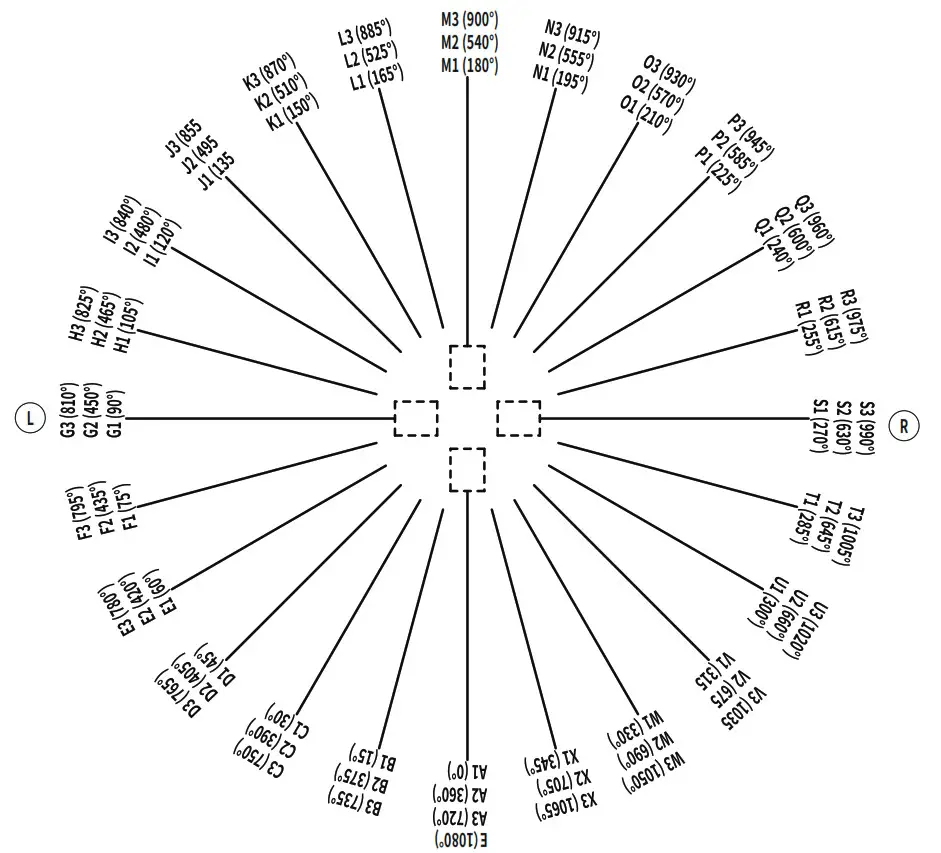
(2)Drive time
Neighbouring injection angles take 20 ms to reach. For example, the nozzle drive from A1 to B1, it takes 20ms. when operator design a show to synchronize to music, this drive time must be calculated.
The following table shows the time of the nozzle reaching the required angle from NO.A1:
| No. | Angles | Drive time needed |
| NO.A1 | 0° | 0ms |
| NO.B1 | 15° | 20ms |
| NO.C1 | 30° | 40ms |
| NO.D1 | 45° | 60ms |
| NO.E1 | 60° | 80ms |
| NO.F1 | 75° | 100ms |
| NO.G1 | 90° | 120ms |
| NO.H1 | 105° | 140ms |
| NO.I1 | 120° | 160ms |
| NO.J1 | 135° | 180ms |
| NO.K1 | 150° | 200ms |
| NO.L1 | 165° | 220ms |
| NO.M1 | 180° | 240ms |
| NO.N1 | 195° | 260ms |
| NO.O1 | 210° | 280ms |
| NO.P1 | 225° | 300ms |
| NO.Q1 | 240° | 320ms |
| NO.R1 | 255° | 340ms |
| NO.S1 | 270° | 360ms |
| NO.T1 | 285° | 380ms |
| NO.U1 | 300° | 400ms |
| NO.V1 | 315° | 420ms |
| NO.W1 | 330° | 440ms |
| NO.X1 | 345° | 460ms |
| NO.A2 | 360° | 480ms |
| NO.B2 | 375° | 500ms |
| NO.C2 | 390° | 520ms |
| NO.D2 | 405° | 540ms |
| NO.E2 | 420° | 450ms |
| … | … | … |
| NO.A3 | 720° | 960ms |
| … | … | … |
| E(END) | 1080° | 1440ms |
(3)Sequence list
Circle Flamer X-F3600 with more than 160 kind of preset firing sequences, 94 kind of firing sequences under full cycle mode.
Operators use related channel DMX value or sequence No. to access certain sequences. Sequence list as below:
Single Ignition Sequence List
| Sequence No. | Ignition angle NO. | Description | Nozzle Movement | Firing Duration | CH5 DMX Reference Value |
| 1 | A2 | Single Ignition SHORT flame | Static | 0.11s | 3-5 |
| 2 | B2 | Single Ignition SHORT flame | Static | 0.11s | 6-7 |
| 3 | C2 | Single Ignition SHORT flame | Static | 0.11s | 810 |
| 4 | D2 | Single Ignition SHORT flame | Static | 0.11s | 11-12 |
| 5 | E2 | Single Ignition SHORT flame | Static | 0.11 s | 13-15 |
| 6 | F2 | Single Ignition SHORT flame | Static | 0.11s | 16-17 |
| 7 | G2 | Single Ignition SHORT flame | Static | 0.11s | 18-20 |
| 8 | H2 | Single Ignition SHORT flame | Static | 0.11s | 21-22 |
| 9 | 12 | Single Ignition SHORT flame | Static | 0.11s | 23-25 |
| 10 | J2 | Single Ignition SHORT flame | Static | 0.11s | 26-28 |
| 11 | K2 | Single Ignition SHORT flame | Static | 0.11s | 29-30 |
| 12 | L2 | Single Ignition SHORT flame | Static | 0.11s | 31-33 |
| 13 | M2 | Single Ignition SHORT flame | Static | 0.11s | 34-35 |
| 14 | N2 | Single Ignition SHORT flame | Static | 0.11s | 36-38 |
| 15 | 2 | Single Ignition SHORT flame | Static | 0.11s | 39-40 |
| 16 | P2 | Single ignition SHORT flame | Static | 0.11s | 41-43 |
| 17 | Q2 | Single ignition SHORT flame | Static | 0.11s | 44-45 |
| 18 | R2 | Single ignition SHORT flame | Static | 0.11s | 46-48 |
| 19 | S2 | Single ignition SHORT flame | Static | 0.11s | 49-50 |
| 20 | T2 | Single ignition SHORT flame | Static | 0.11s | 51-53 |
| 21 | U2 | Single ignition SHORT flame | Static | 0.11s | 54-56 |
| 22 | V2 | Single ignition SHORT flame | Static | 0.11s | 57-58 |
| 23 | W2 | Single ignition SHORT flame | Static | 0.11s | 59-61 |
| 24 | X2 | Single ignition SHORT flame | Static | 0.11s | 62-63 |
| 25 | A2 | Single Ignition LONG flame | Static | 0.56s | 64-66 |
| 26 | B2 | Single Ignition LONG flame | Static | 0.56s | 67-68 |
| 27 | C2 | Single Ignition LONG flame | Static | 0.56s | 69-71 |
| 28 | D2 | Single Ignition LONG flame | Static | 0.56s | 72-73 |
| 29 | E2 | Single Ignition LONG flame | Static | 0.56s | 74-76 |
| 30 | F2 | Single Ignition LONG flame | Static | 0.56s | 77-79 |
| 31 | G2 | Single ignition LONG flame | Static | 0.34s | 80-81 |
| 32 | H2 | Single ignition LONG flame | Static | 0.34s | 82-84 |
| 33 | 12 | Single ignition LONG flame | Static | 0.34s | 85-86 |
| 34 | J2 | Single ignition LONG flame | Static | 0.34s | 87-89 |
| 35 | K2 | Single ignition LONG flame | Static | 0.34s | 90-91 |
| 36 | L2 | Single ignition LONG flame | Static | 0.34s | 92-94 |
| 37 | M2 | Single ignition LONG flame | Static | 0.34s | 95-96 |
| 38 | N2 | Single ignition LONG flame | Static | 0.34s | 97-99 |
| 39 | 2 | Single ignition LONG flame | Static | 0.34s | 100-101 |
| 40 | P2 | Single ignition LONG flame | Static | 0.34s | 102-104 |
| 41 | Q2 | Single ignition LONG flame | Static | 0.34s | 105-107 |
| 42 | R2 | Single ignition LONG flame | Static | 0.34s | 106-110 |
| 43 | S2 | Single ignition LONG flame | Static | 0.34s | 111-112 |
| 44 | T2 | Single ignition LONG flame | Static | 0.34s | 113-114 |
| 45 | U2 | Single ignition LONG flame | Static | 0.34s | 115-117 |
| 46 | V2 | Single ignition LONG flame | Static | 0.34s | 118-119 |
| 47 | W2 | Single ignition LONG flame | Static | 0.34s | 120-121 |
| 48 | X2 | Single ignition LONG flame | Static | 0.34s | 122-124 |
Step Sequences List
| Sequence No. | Ignition angle NO. | Description | Nozzle Movement | Firing Duration | CH5 DMX Reference Value |
| 49 | Step from M2-M3 | 30°- lcycle – SHORT flame | Clockwise | 2.04s | 125-127 |
| 50 | Step from M2-M1 | 30°- lcycle – SHORT flame | Anticlockwise | 2.04s | 128-130 |
| 51 | Step from M2-M3 | 45°- lcycle – SHORT flame | Clockwise | 1.25s | 131-132 |
| 52 | Step from M2-M1 | 45°- lcycle – SHORT flame | Anticlockwise | 1.34s | 133-135 |
| 53 | Step from M2-A3 | 30°- 1.5 cycle – SHORT flame | Clockwise | 3.04s | 136-137 |
| 54 | Step from M2-A1 | 30°- 1.5 cycle – SHORT flame | Anticlockwise | 3.04s | 138-140 |
| 55 | Step from M2-A3 | 45°- 1.5cycle – SHORT flame | Clockwise | 2.2s | 141-142 |
| 56 | Step from M2-A1 | 45°- 1.5cycle – SHORT flame | Anticlockwise | 2.2s | 143-145 |
| 57 | Step from Al -E | 30°- 3cycle – SHORT flame | Clockwise | 6.80s | 146-147 |
| 58 | Step from E-A1 | 30°- 3cycle – SHORT flame | Anticlockwise | 6.80s | 148-150 |
| 59 | Step from Al -E | 45°- 3cycle – SHORT flame | Clockwise | 4.8s | 151-152 |
| 60 | Step from E-A1 | 45°- 3cycle – SHORT flame | Anticlockwise | 4.8s | 153-155 |
| 61 | Step from Al -E | Accelerate-3 cycles – SHORT flame | Clockwise | 8.1s | 156-158 |
| 62 | Step from E-A1 | Accelerate-3 cycles – SHORT flame | Anticlockwise | 8.1s | 159-160 |
| 63 | Step from Al -E | Decelerate-3 cycles – SHORT flame | Clockwise | 8.1s | 161-163 |
| 64 | Step from E-A1 | Decelerate-3 cycles – SHORT flame | Anticlockwise | 8.1s | 164-165 |
| 65 | Step from M2c>M3 | Back and forth-4cycles-SHORT flame | C>AC>C>AC | 5.4s | 166-168 |
| 66 | Step from M2<>M1 | Back and forth-4cycles-SHORT flame | AC>C >AC>C | 5.4s | 169-170 |
Wave Sequence List
| Sequence No. | Ignition angle NO. | Description | Nozzle Movement | Firing Duration | CH5 DMX Reference Value |
| 67 | Wave M2–>M3 | Clover shape wave-1cycle | Clockwise | 2.37s | 171-173 |
| 68 | Wave M2–>M1 | Clover shape wave-1cycle | Anticlockwise | 2.37s | 174-175 |
| 69 | Wave M2–>M3 | Fast-lcycle | Clockwise | 0.83s | 176-178 |
| 70 | Wave M2–>M1 | Fast-lcycle | Anticlockwise | 0.83s | 179-181 |
| 71 | Wave M2–>M3 | Slow-lcycle | Clockwise | 1.27s | 182-183 |
| 72 | Wave M2–>M1 | Slow-lcycle | Anticlockwise | 1.27s | 182-186 |
| 73 | Wave M2–>A3 | Fast-1.5cycle | Clockwise | 1.17s | 187-188 |
| 74 | Wave M2–>A1 | Fast-1.5cycle | Anticlockwise | 1.17s | 189-191 |
| 75 | Wave M2–>A3 | Slow-1.5cycle | Clockwise | 1.9s | 192-193 |
| 76 | Wave M2–>A1 | Slow-1.5cycle | Anticlockwise | 1.9s | 194-196 |
| 77 | Wave A1–>E | Fast-3cycle | Clockwise | 2.88s | 197-198 |
| 78 | Wave E–>A1 | Fast-3cycle | Anticlockwise | 2.88s | 199-201 |
Additional Sequences List
| Sequence No. | Ignition angle NO. | Description | Nozzle Movement | Firing Duration | CH5 DMX Reference Value |
| 79 | Step from F2-T2 | 150- SHORT flame Step sequence | L->R | 2.6s | 202-203 |
| 80 | Step from T2-F2 | 15°- SHORT flame Step sequence | R->L | 2.6s | 204-206 |
| 81 | Step 12-K2-M2-02-Q2 | 30°- SHORT flame Step sequence | L->R | 1.25s | 207-209 |
| 82 | Step Q2-02-M2-K2-12 | 30°- SHORT flame Step sequence | R->L | 1.25s | 210-211 |
| 83 | Step J2-M2-Q2 | 45°- SHORT flame Step sequence | L->R | 0.9s | 212-214 |
| 84 | Step Q2-M2-J2 | 45°- SHORT flame Step sequence | R->L | 0.9s | 215-216 |
| 85 | Step K2-02 | 60°- SHORT flame Step sequence | L->R | 0.6s | 217-219 |
| 86 | Step 02-K2 | 60°- SHORT flame Step sequence | R->L | 0.6s | 218-221 |
| 87 | Wave J2–>P2 | Middle wave sequence | L->R | 3.5s | 222-224 |
| 88 | Wave P2–>J2 | Middle wave sequence | R->L | 3.5s | 225-226 |
| 89 | Wave F2–>M2 | SHORT wave sequence | L->R | 4.3s | 227-229 |
| 90 | Wave T2–>M2 | SHORT wave sequence | R->L | 4.3s | 230-232 |
| 91 | Wave F2–>T2 | LONG wave sequence | L->R | 8.5s | 233-234 |
| 92 | Wave T2–>F2 | LONG wave sequence | R->L | 8.5s | 235-237 |
| 93 | Step from 12<>Q2 | 30°- SHORT flame Step sequence | L->R->L->R->L | 5s | 238-239 |
| 94 | Step from Q2<>12 | 30°- SHORT flame Step sequence | R->L->R->L->R | 5s | 240-242 |
Half Cycle Mode
(1)Angle definitions
In half-cycle mode, CIRCLE FLAMER X-F3600 with firing angle of ±105°, below schematic shows firing angles from Audience Side view. ±105° divided into 15 projection directions as below:
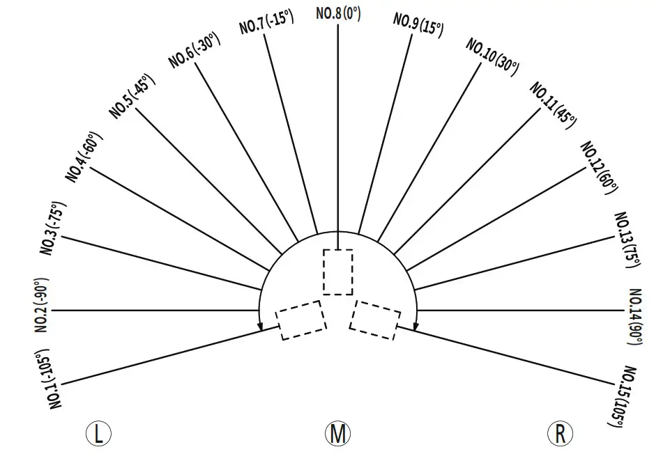
(2)Drive time
Time needed for the motor drive from NO.8 to relevant angle.
| No. | Angles | Drive time needed |
| NO.1 | -105° | 170ms |
| NO.2 | -90° | 150ms |
| NO.3 | _750 | 130ms |
| NO.4 | -60° | 110ms |
| NO.5 | -45° | 90ms |
| NO.6 | -30° | 70ms |
| NO.7 | -15° | 50ms |
| NO.8 | 0° | Oms |
| NO.9 | 15° | 50ms |
| NO.10 | 30° | 70ms |
| NO.11 | 45° | 90ms |
| NO.12 | 60° | 110ms |
| NO.13 | 75° | 130ms |
| NO.14 | 90° | 150ms |
| NO.15 | 105° | 170ms |
For example for the motor drive from 0° to 45°, it need 90ms, when operator design a show to synchronize to music, this drive time must be calculated.
(3)Sequence list
Circle Flamer X-F3600 with more than 160 kind of preset firing sequences, 70 kind of firing sequences under half cycle mode.
Operator use related channel DMX value or sequence No. to access certain sequence. Sequence list as below:
Single Ignition Sequence List
| Sequence No. | Ignition angle NO. | Ignition angle NO. | Description | Nozzle Movement | Firing Duration | CH5 DMX Reference Value |
| 1 | NO.1 | -105° | Single Ignition SHORT flame | Static | 0.19s | 3-5 |
| 2 | NO.2 | -90° | Single Ignition SHORT flame | Static | 0.19s | 6-7 |
| 3 | NO.3 | -75° | Single Ignition SHORT flame | Static | 0.19s | 810 |
| 4 | NO.4 | -60° | Single Ignition SHORT flame | Static | 0.19s | 11-12 |
| 5 | NO.5 | -45° | Single Ignition SHORT flame | Static | 0.19s | 13-15 |
| 6 | NO.6 | -30° | Single Ignition SHORT flame | Static | 0.19s | 16-17 |
| 7 | NO.7 | -15° | Single Ignition SHORT flame | Static | 0.19s | 18-20 |
| 8 | NO.8 | 0° | Single Ignition SHORT flame | Static | 0.19s | 21-22 |
| 9 | NO.9 | 15° | Single Ignition SHORT flame | Static | 0.19s | 23-25 |
| 10 | NO.10 | 30° | Single Ignition SHORT flame | Static | 0.19s | 26-28 |
| 11 | NO.11 | 45° | Single Ignition SHORT flame | Static | 0.19s | 29-30 |
| 12 | NO.12 | 60° | Single Ignition SHORT flame | Static | 0.19s | 31-33 |
| 13 | NO.13 | 75° | Single Ignition SHORT flame | Static | 0.19s | 34-35 |
| 14 | NO.14 | 90° | Single Ignition SHORT flame | Static | 0.19s | 36-38 |
| 15 | NO.15 | 105° | Single Ignition SHORT flame | Static | 0.19s | 39-40 |
| 16 | NO.1 | -105° | Single ignition LONG flame | Static | 0.56s | 41-43 |
| 17 | NO.2 | -90° | Single ignition LONG flame | Static | 0.56s | 44-45 |
| 18 | NO.3 | -75° | Single ignition LONG flame | Static | 0.56s | 46-48 |
| 19 | NO.4 | -60° | Single ignition LONG flame | Static | 0.56s | 49-50 |
| 20 | NO.5 | -45° | Single ignition LONG flame | Static | 0.56s | 51-53 |
| 21 | NO.6 | -30° | Single ignition LONG flame | Static | 0.56s | 54-56 |
| 22 | NO.7 | -15° | Single ignition LONG flame | Static | 0.56s | 57-58 |
| 23 | NO.8 | 0° | Single ignition LONG flame | Static | 0.56s | 59-61 |
| 24 | NO.9 | 15° | Single ignition LONG flame | Static | 0.56s | 62-63 |
| 25 | NO.10 | 30° | Single ignition LONG flame | Static | 0.56s | 64-66 |
| 26 | NO.11 | 45° | Single Ignition LONG flame | Static | 0.56s | 67-68 |
| 27 | NO.12 | 60° | Single Ignition LONG flame | Static | 0.56s | 69-71 |
| 28 | NO.13 | 75° | Single Ignition LONG flame | Static | 0.56s | 72-73 |
| 29 | NO.14 | 90° | Single Ignition LONG flame | Static | 0.56s | 74-76 |
| 30 | NO.15 | 105° | Single Ignition LONG flame | Static | 0.56s | 77-79 |
Step Sequences List
| Sequence No. | Ignition angle NO. | Description | Nozzle Movement | Firing Duration | CH5 DMX Reference Value |
| 31 | Step from 1-15 | SHORT flame Step sequence | Clockwise | 2.04s | 125-127 |
| 32 | Step from 15-1 | SHORT flame Step sequence | Anticlockwise | 2.04s | 128-130 |
| 33 | Step 5-8-11 | SHORT flame Step sequence | Clockwise | 1.25s | 131-132 |
| 34 | Step 11-8-5 | SHORT flame Step sequence | Anticlockwise | 1.34s | 133-135 |
| 35 | Step 6-10 | SHORT flame Step sequence | Clockwise | 3.04s | 136-137 |
| 36 | Step 10-6 | SHORT flame Step sequence | Anticlockwise | 3.04s | 138-140 |
| 37 | Step 4-6-8-10-12 | SHORT flame Step sequence | Clockwise | 2.2s | 141-142 |
| 38 | Step 12-10-8-6-4 | SHORT flame Step sequence | Anticlockwise | 2.2s | 143-145 |
| 39 | Step 8-6-10-4-12 | SHORT flame Step sequence | Clockwise | 6.80s | 146-147 |
| 40 | Step 8-10-6-12-4 | SHORT flame Step sequence | Anticlockwise | 6.80s | 148-150 |
| 41 | Step from 1-15 | LONG flame Step sequence | Clockwise | 4.8s | 151-152 |
| 42 | Step from 15-1 | LONG flame Step sequence | Anticlockwise | 4.8s | 153-155 |
| 43 | Step 5-8-11 | LONG flame Step sequence | Clockwise | 8.1s | 156-158 |
| 44 | Step 11-8-5 | LONG flame Step sequence | Anticlockwise | 8.1s | 159-160 |
| 45 | Step 6-10 | LONG flame Step sequence | Clockwise | 8.1s | 161-163 |
| 46 | Step 10-6 | LONG flame Step sequence | Anticlockwise | 8.1s | 164-165 |
| 47 | Step 4-6-8-10-12 | LONG flame Step sequence | C>AC>C>AC | 5.4s | 166-168 |
| 48 | Step 12-10-8-6-4 | LONG flame Step sequence | AC>C >AC>C | 5.4s | 169-170 |
| 49 | Step 8-6-10-4-12 | LONG flame Step sequence | C>AC>C>AC | 5.4s | 166-168 |
| 50 | Step 8-10-6-12-4 | LONG flame Step sequence | AC>C >AC>C | 5.4s | 169-170 |
Wave Sequence List
| Sequence No. | Ignition angle NO. | Description | Nozzle Movement | Firing Duration | CH5 DMX Reference Value |
| 51 | Wave 5–>11 | Middle wave sequence | L->R | 1.99s | 131-132 |
| 52 | Wave 11–>5 | Middle wave sequence | L->R | 1.99s | 133-135 |
| 53 | Big wave 1–>15 | LONG wave sequence | L->R | 4.14s | 136-137 |
| 54 | Big wave 15–>1 | LONG wave sequence | R->L | 4.14s | 138-140 |
| 55 | Wave 8–>1 | Middle wave sequence | M->L | 2.18s | 141-142 |
| 56 | Wave 8–>15 | Middle wave sequence | M->R | 2.18s | 143-145 |
| 57 | Wave 1–>8 | Middle wave sequence | L->M | 2.16s | 146-147 |
| 58 | Wave 15–>8 | Middle wave sequence | R->M | 2.16s | 148-150 |
| 59 | Wave 8–>11 | SHORT wave sequence | M->R | 1.12s | 151-152 |
| 60 | Wave 8–>5 | SHORT wave sequence | M->L | 1.12s | 153-155 |
| 61 | Wave 5–>8 | SHORT wave sequence | L->M | 1.24s | 156-158 |
| 62 | Wave 11>–8 | SHORT wave sequence | R->M | 1.24s | 159-160 |
Additional Sequences List
| Sequence No. | Ignition angle NO. | Description | Nozzle Movement | Firing Duration | CH5 DMX Reference Value |
| 63 | Step 2-14 | SHORT flame Step cerpienre | I –A | n fins | 161-163 |
| 64 | Step 14-7 | SHORT flame Step sequence | R->I | 0 60c | 164-165 |
| 65 | Step 2-14 | LONG flame Step sequence | L->R | 1.38s | 166-168 |
| 66 | Step 14-2 | LONG flame Step sequence | R->L | 1.38s | 169-170 |
| 67 | Step 8-14 | SHORT flame Step sequence | M->L | 1.85s | 171-173 |
| 68 | Step 8-2 | SHORT flame Step sequence | M->R | 1.85s | 174-175 |
| 69 | Step 8-14 | LONG flame Step sequence | M->L | 4.18s | 146-147 |
| 70 | Step 8-2 | LONG flame Step sequence | M->R | 4.18s | 148-150 |
DMX Control
| Channel | Function |
| C H1 | Manual Angle setup: (1)Full Cycle Mode: (0-255) angle change from A1(0°) to E(1080°), (128) is straight upward M2(540°) (2)Half Cycle Mode: (0-255) angle change from -105° to 105°, (128) is straight upward (0°) |
| CH2 | Manual Speed setup: (0) Max Speed, (1-254) Speed increase, (255) Max Speed |
| CH3 | Ignition ON/OFF: (0-253) Ignition OFF, (254-255) Ignition ON |
| CH4 | Firing Duration setup: 0 and 255 is permanent fire (10s is limit duration time); 1-254 is 10-2540ms duration time (Manual firing duration = DMX Value * 10ms) |
| CH5 | Program sequence setup: (0-2) no preset sequence; (3-255) preset sequence. DMX value = 2 + Sequence No.*2.55 (ROUND OFF) Detail information(CH5 DMX Reference Value) you can see the sequences list above. |
| CH6 | Firing Pressure setup: (0-49) Pressure Relief Mode (Emergency Stop), (50-200) Pressure Armed Mode, (201-255) Pressure Relief Mode (Emergency Stop) |
>Channel 1 (CH1)-Full Cycle Mode : Angle Setup
| Angle No. | Angle | DMX value |
| Al | 0° | 0 |
| B1 | 15° | 4 |
| Cl | 30° | 7 |
| D1 | 45° | 11 |
| E1 | 60° | 14 |
| Fl | 75° | 18 |
| GI | 90° | 21 |
| H1 | 105° | 25 |
| Il | 120° | 28 |
| 11 | 135° | 32 |
| K1 | 150° | 35 |
| LI | 165° | 39 |
| MI | 180° | 42 |
| N1 | 195° | 46 |
| 1 | 210° | 50 |
| P1 | 225° | 53 |
| Q1 | 240° | 57 |
| RI | 255° | 60 |
| S1 | 270° | 64 |
| T1 | 285° | 67 |
| U1 | 300° | 71 |
| V1 | 315° | 74 |
| W1 | 330° | 78 |
| X1 | 345° | 81 |
| A2 | 360° | 85 |
| B2 | 375° | 89 |
| C2 | 390° | 92 |
| D2 | 405° | 96 |
| E2 | 420° | 99 |
| … | … | |
| A3 | 720° | 170 |
| … | … | |
| E(END) | 1080° | 255 |
1. The first channel controls the firing angle. It defines to which angle the nozzle of CIRCLE FLAMER move to. The angle can be chosen anywhere between0° to 1080° (DMX value 0 to 255).
2. The DMX value for angle of 0° is 3.5 (round up 4). the following formula can be used to calculate all other angles ∠ in degree.
DMX Value = ∠ * 0.2361
> Channel 1 (CH1)-Half Cycle Mode : Angle Setup
| Angle No. | Angles | DMX Value |
| 1 | -105° | 0 |
| 2 | -90° | 18 |
| 3 | -75° | 36 |
| 4 | -60° | 54 |
| 5 | -45° | 73 |
| 6 | -30° | 91 |
| 7 | -15° | 109 |
| 8 | 0° | 128 |
| 9 | 15° | 146 |
| 10 | 30° | 165 |
| 11 | 45° | 183 |
| 12 | 60° | 201 |
| 13 | 75° | 219 |
| 14 | 90° | 237 |
| 15 | 105° | 255 |
1. The first channel controls the firing angle. It defines to which angle the nozzle of CIRCLE FLAMER move to. The angle can be chosen anywhere between -105° to +105° (DMX value 0 to 255).
2. The DMX value for angle of 0° is 127.5 (round up 128). Use this value, following formula can be used to calculate all other angles ∠ in degree. Please always note the prefix of the angle.
DMX Value = 127.5 + (∠ * 1.2145)
> Channel 2 (CH2): Speed Setup
| CH2: Speed Setup | |||
| DMX value | 0 | 1-254 | 255 |
| Speed | Max Speed | Incremental of Speed | Max Speed |
The second channel defines the rotate speed. It work together with Channel 1 for manual firing.
> Channel 3 (CH3): Ignition ON/OFF
| CH3: Ignition | ||
| DMX value | 0-253 | 254-255 |
| Ignition | CIRCLE FLAMER won’t ignite | CIRCLE FLAMER ignites |
The third channel activates the actual ignition. If the DMX value of this channel higher than 253, the CIRCLE FLAMER will ignite.
> Channel 4 (CH4): Firing Duration setup
| Manual Firing Duration setup | ||||||||
| DMX value | 0 | 1 | 2 | 3 | 4 | 254 | 255 | |
| Firing Duration | Permanent | Oms | 10ms | 20ms | 30ms | 2540ms | Permanent | |
The fourth channel is the firing duration setup.
Below formula can be used to calculate the firing duration (ms):
T = DMX Value * 10
> Channel 5 (CH5): Program Sequence setup
The fifth Channel allows to firing a preset sequence. Three DMX values can be used for one of the programmed firing sequence from above sequence list (refer to above sequence list table).
Below formula can be used to calculate firing sequence:
DMX Value = 2+ Sequence No.*2.55
| Firing sequence mode/related firing channel | |||||||
| DMX value | 0-2 | 3-5 | 6-7 | 179-181 | 240-242 | ||
| Sequence No. | N/A | 1 | 2 | 70 | 94 | ||
| Mode | Half Cycle Mode(180) | — | |||||
| Full Cycle Mode(360) | |||||||
> Channel 6 (CH6): Mode setup
The sixth channel is the working mode of pump.
When the safety lock located at TEST MODE, set DMX value between 50-200 to test the system. For safety, the device will not pressuriser.
When the safety lock located at USER MODE, the device pressuriser activated by set DMX value between 50-200. The device can only make ignitions in Firing mode.
| CH6: Mode setup | |||
| DMX value | 0-49 | 50-200 | 201-255 |
| State | Pressure Relief | Pressure Armed | Pressure Relief |
• Example 1: DMX console control (Half Cycle Mode)
- Set nozzle straight up
(CH1 Angle = 128, CH2 Speed = 0, CH3 Ignition = 0, CH4 Firing duration = 0, CH5 Program sequence = 0, CH6 Compres sion mode = 50~200) - Set preset Sequence No. 31
(CH1 Angle = 128, CH2 Speed = 0, CH3 Ignition = 0, CH4 Firing duration = 0, CH5 Program sequence DMX value = 80, CH6 Compression mode = 50~200) - Ignition
( CH1 Angle = 128,CH2 Speed = 0,CH3 Ignition = 255,CH4 Firing duration = 0,CH5 Program sequence DMX value = 80, CH6 Compression mode = 50~200)
NOTE: After firing, The DMX value of CH3 must fall below 254, before an ignition can be made again. CH1 defines the nozzle position after firing.
• Example 2: Firing with DMX control (wave firing, Half Cycle Mode)
- Set firing nozzle to the start point
(CH1 Angle = 0, CH2 Speed = 255, CH3 Ignition = 0, CH6 Compression mode = 50~200) - Set up firing speed
(CH1 Angle = 0, CH2 Speed = 50, CH3 Ignition = 0, CH6 Compression mode = 50~200) - Set firing end point and ignition
(CH1 Angle = 255, CH2 Speed = 50, CH3 Ignition = 255, CH6 Compression mode = 50~200) - Firing Nozzle will firing and make movement from start point to end point
NOTE: After firing, The DMX value of CH3 must fall below 254, before an ignition can be made again.
• Example 3: Firing with DMX control (fixed firing duration, Half Cycle Mode)
- Set nozzle straight up
(CH1 Angle = 128, CH2 Speed = 0, CH3 Ignition = 0, CH4 Firing duration = 0, CH6 Compression mode = 50~200) - Set firing duration 1s
(CH1 Angle = 128, CH2 Speed = 0, CH3 Ignition = 0, CH4 Firing duration = 100, CH6 Compression mode = 50~200) - Firing 1s
(CH1 Angle = 128, CH2 Speed = 0, CH3 Ignition = 255, CH4 Firing duration = 100, CH6 Compression mode = 50~200)
NOTE: After firing, The DMX value of CH3 must fall below 254, before an ignition can be made again.
6. Operating with SHOWVEN host controller ZK6200/ZK6300
1) Hardware description
- MODEL
- ZK6200
- Dimension
- 390×300×110mm
- Weight
- 3.5kgWork
- Input
- 110-240Vac, 50/60Hz
- Work power
- 15w
- Work Temp.
- -10℃~ 50 ℃
- Interface
- 2*CAN port
2* media port (music trigger)
2*MIDI port (music trigger)
1* DMX512 input
1*DMX512 output.
- 2*CAN port
Support Max. 200m communication cable
3350 mAH Li-battery (5h battery life when fully charged)
SHOWVEN host controller introduction
a) Standard DMX512 signal output.
b) Support 18units CIRCLE FLAMER (ZK6200) or 54units CIRCLE FLAMER (ZK6300) at the same time.
c) 5 standard dynamic modes: Synchronization, Center to Ends, Ends to Center, Left to Right, Right to Left. And a user defin able Special Effect mode, support 8 files, each file support 36000 lines maximum (effects lasts for 30min).
d) Multi trigger sources: manual, music or midi input.
e) RDMX monitoring function: system can send back circle flamer working status info such as pressure, warming etc. and display on the screen.
f) Emergency stop function.
3) Operational Panel
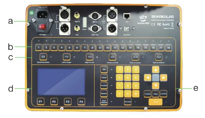
a) Cable Connection Area
AC Input: AC Power Input;
CAN: CAN communication input/output;
MIDI In: Midi time synchronous signal input;
DMX 512: DMX signal input/output;
LAN: network interface;
USB: program download interface, SparkularEdit200 software port.
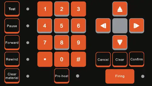
b) Manual firing operation region

c) Mode Selection Area

There are 5 standard dynamic mode and 1 special effects mode. Each mode support 8 files, it can be switched easily on the mode selection area.
d) LCD display Area
F1: Main menu;
F2: File selection;
F3: Configuration;
F4: About host controller.
e) Edit/Control Area
Set circle flamer DMX address as below:
| CIRCLE FLAMER No. | DMX Address |
| 1 | 1 |
| 2 | 7 |
| 3 | 13 |
| 4 | 19 |
| 5 | 25 |
| 6 | 31 |
| 7 | 37 |
| 8 | 43 |
| 9 | 49 |
| 10 | 55 |
| 11 | 61 |
| 12 | 67 |
| 13 | 73 |
| 14 | 79 |
| 15 | 85 |
| 16 | 91 |
| 17 | 97 |
| 18 | 103 |
Note: wrong DMX address setup may leads to circle flamer out of control.
Setup of Host controller:
1. Press “F3” enter host controller configuration menu, DEVICE choose “CIRCLE FLAMER” as below.
2. Set Start No. and End No. of device.
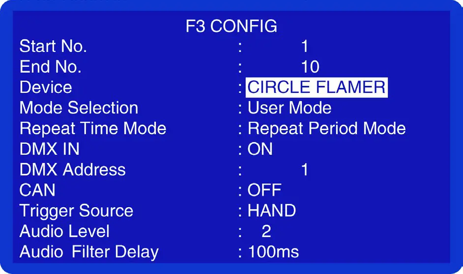
Press “F1” back to main interface.
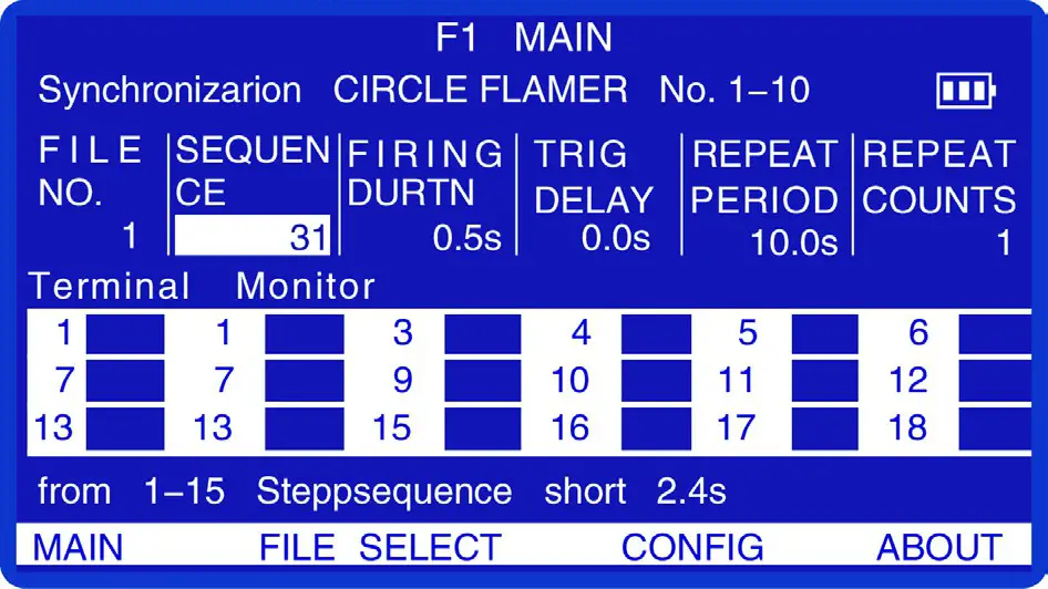
Press “PRE-HEAT”, activate the compression of device.
1. Manual firing: Enter SEQUENCE No.99, press 1-18 to firing each unit, CIRCLE FLAMER can only firing at vertical upward.
2. Sequence firing: eg: firing at SEQUENCE 31, entering 31 at SEQUENCE, entering FIRING DURATION (Firing duration normally set at 0.5s, even the sequence firing duration is longer than 0.5s, the SEQUENCE will fully executed) , set the repeat counts, press “FIRING” to activate the device.
NOTE: Put safety lock at “TEST MODE” to check the signal connection and nozzle rotation status before use the device for firing.
For Emergency stop, press “PRE-HEAT”, device will enter pressure relief mode, and stop emergently.
▲Maintenance
- To maintain the system in good performance and running status, it is recommended to running the device at least once per month.
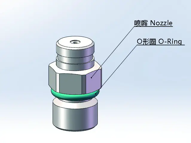
- Maintenance of the nozzle: Nozzle need to be cleaned up , and it is recommended that once every six months (depending on the environment and frequency of use). In the process of using the equipment, if the flame shape is seriously deformed or the fuel injection line is significantly deformed or coarsened, the nozzle should be removed immediately for cleaning.

- Maintenance of the O-ring: If it is found that the O-ring of the nozzle is damaged or ageing when cleaning the nozzle, the O-ring should be replaced in time (material and size of O- ring: fluoro rubber O-ring, the outermost diameter is 14 mm, and the line diameter is 2 mm).

- In order to lubricate the pipeline and pump it is highly recommended to add 10-20ml castor oil per 10L canister.
- Software can be upgraded with download cable from SHOWVEN.
- Switchable power input design, switchable between 110V and 220V as show below (voltage will show on it). The power supply is located on the side of the electric control, and you should remove the cover in order to change it.
Warranty Instructions
▲Sincere thanks for your choosing Circle Flamer X-F3600, you will receive quality service from us.
▲The product warranty period is one year. If there are any quality problems within 7 days after ship ping out from our factory, we can exchange a brand new same model machine for you.
▲We will offer free of charge maintenance service for machines which with hardware malfunction (except for the instrument damage caused by human factors)in warranty period. Please don’t repair machine without factory permission.
★Below situations NOT included in warranty service:
- Damage caused by improper transportation, usage, management, and maintenance, or damage
caused by human factors; - Disassemble, modify or repair products without Showven’s permission;
- Damage caused by external reasons (lightning strike, power supply etc);
- Damage caused by improper installation or use;
For product damage not included in warranty range, we can provide paid service.
★Invoice and warranty card are necessary when applying for maintenance service from SHOWVEN.
Warranty Card
| Product Name: | Serial No. | ||
| Purchase Date: | |||
| Address: | |||
| Problem Feedback: | |||
| Actual Problem: | |||
| Maintenance DetaiI: | |||
| Service Engineer: | Service Date: | ||
SHOWVEN®

https://www.facebook.com/Showven-228026294663699/?modal=admin_todo_tour
Showven Technologies Co., Ltd.
Add: Building B1, Changsha E Center No.18, Xiangtai Road, Liuyang Economic Development
Zone, Changsha City, 410300, Hunan Province, P.R.China.
Tel : +86-731-83833068
Web: www.showven.cn
E-mail: [email protected]


