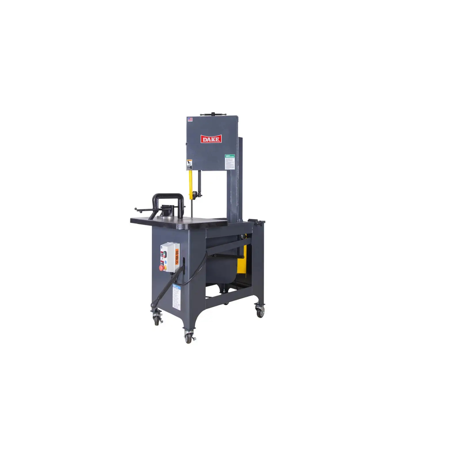
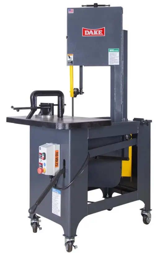
DAKE SXC Work-A-Matic Bandsaw
DAKE STANDARD LIMITED WARRANTY
Finished Machines
– Dake warrants to the original purchaser the finished machine manufactured or distributed by it to be free from defects in material and workmanship under normal use and service within 1 year (12 months) from the delivery date to the end user.
Parts
– Dake warrants to the original purchaser the component part manufactured or distributed by it to be free from defects in material and workmanship under normal use and service within 30 days from the delivery date to the end user.
– The standard limited warranty includes the replacement of the defective component part at no cost to the end user.
Sale of Service (Repairs)
– Dake warrants to the original purchaser the component part repaired by Dake Corporation at the manufacturing facility to be free from defects in material and workmanship under normal use and service within 90 days from the return date to the end user, as it pertains to the repair work completed.
– The standard limited warranty includes repair of the defective component part, at no cost to the end user.
Warranty Process
– Subject to the conditions hereinafter set forth, the manufacturer will repair or replace any portion of the product that proves defective in materials or workmanship. The manufacturer retains the sole right and option, after inspection, to determine whether to repair or replace defective equipment, parts, or components. The manufacturer will assume ownership of any defective parts replaced under this warranty.
– All requested warranty claims must be communicated to the distributor or representative responsible for the sale. Once communication has been initiated, Dake Customer Service must be contacted for approval:
- Phone: (800) 937-3253
- Email: [email protected]
– When contacting Dake, please have the following information readily available:
- Model #
- Serial #
- Sales Order #
– Purchasers who notify Dake within the warranty period will be issued a Case number and/or a Return Material Authorization (RMA) number. If the item is to be returned per Dake’s request, the RMA number must be clearly written on the exterior packaging. Any item shipped to Dake without an RMA will not be processed.
Warranty Exceptions
The following conditions are not applicable to the standard limited warranty:
(a) Part installation or machine service was not completed by a certified professional, and is not in accordance with applicable local codes, ordinances, and good trade practices.
(b) Defects or malfunctions resulting from improper installation or failure to operate or maintain the unit in accordance with the printed instructions provided.
(c) Defects or malfunctions resulting from abuse, accident, neglect, or damage outside of prepaid freight terms.
(d) Normal maintenance service or preventative maintenance, and the parts used in connection with such service.
(e) Units and parts which have been altered or repaired, other than by the manufacturer or as specifically authorized by the manufacturer.
(f) Alterations made to the machine that were not previously approved by the manufacturer, or that are used for purposes other than the original design of the machine.
RETURN & REFUND POLICY
– Thank you for purchasing from Dake! If you are not entirely satisfied with your purchase, we are here to help.
Returns
– All Dake manufactured / distributed machines, parts and couplings include a 30-day return option. These policies are valid from the date of final shipment to the end user. To be eligible for a return, the item must be unused and in the same condition as received.
– All requested warranty claims must be communicated to the distributor or representative responsible for the sale. Once communication has been initiated, Dake Customer Service must be contacted for approval:
- Phone: (800) 937-3253
- Email: [email protected]
– Once the return request has been approved by Customer Service, a representative will supply a Return Material Authorization (RMA) number.
– The returned item must have the provided RMA number clearly marked on the outside packaging. Any item received without an RMA number clearly visible on the packaging will not be processed.
– An RMA number can only be provided by the Dake Customer Service team and must be obtained prior to the return shipment.
Refunds
– Once the item has been received and inspected for damages, a representative will notify the requestor referencing the provided RMA number. If the return is approved, a refund will be issued to the original method of payment, less a 20% restocking fee.
– The restocking fee may be waived if an order is placed at the time of return with likevalue merchandise. Transportation costs are the responsibility of the end user and will not be credited upon return approval.
– Any item that is returned after the initial 30 days or has excessive/obvious use will not be considered for a full refund.
SPECIFICATIONS
| Machine Type | Gravity feed, rolling frame vertical bandsaw |
| Cut Capacity | 9 inches x 14-½ inches |
| Blade (frame) Travel | 9 inches |
| Frame Travel | Gravity counterbalance weight with hydraulic regulation |
| Maximum work height | 14-1/2 inches |
| Blade Width/Length | 1/4 – 3/4 inches / 120 inches |
| Blade Speeds (Feet per Minute) | 70 / 140 / 270 / 540 FPM |
| Worktable Dimensions | 29” x 18” |
| Mitering | 45° |
| Worktable Height from Floor | 36-1/2” |
| Band Wheels | 14” Diameter |
| Horsepower | 1 H.P. |
| Weight | 810 pounds |
| Overall Height | 66” |
| Base Width | 29” |
| Depth | 40” |
| Voltage | 120-volt single phase 230-volt single phase 230-volt three phase 460-volt three phase Machine should be wired to main service by a qualified Electrician |
| AMP |
|
Machine Features:
– Roller blade guides, miter gauge with C-Clamp assembly, headlock, cutting chart, and one standard blade furnished with the machine.
– Large precision ground table for large work surface.
– Heavy-duty gearbox with 4 speed step pulleys for fast speed changes.
– 14” lipped band wheels with rubber tires for smooth operation and long life.
– Blade changes are made quickly with easy access to the band wheels.
– Welded steel base and head frame that is rigid, heavy and durable that helps reduce any wobble and vibration.
– Adjustable counterweight and infinitely variable hydraulic feed pressure regulation, for hands free cutting of most materials.
– Front mounted hydraulic feed control for operator convenience and operation.
– Electrical package that includes low voltage controls, low voltage coil and E-stop button.
– Heavy cast miter gauge and C-Clamp for holding material during the cutting operation, whether it is straight or miter cutting
In the space provided record the serial number and model number of the machine. This information is only found on the black Dake tag. If contacting Dake this information must be provided to assist in identifying the specific machine.
SAFETY WARNINGS
BEFORE USE, ALL SAFTEY INSTRUCTIONS MUST BE READ
– Before the PRESS is used, the instruction manual with this machine must be read and understood. This manual offers safe operation instructions. Offered below are safety instructions designed for the press and general safety instructions that apply to most machinery.
– As will all machinery there are certain hazards involved with operation and use of the machine. Using the machine with respect and caution will considerably lessen the possibility or personal injury. However, if normal safety precautions are overlooked or ignored, personal injury to the operator may result.
– This machine was designed for certain applications only. We strongly recommend that this machine NOT be modified and/or used for any application other than for which it was designed. If you have any questions relative to its application DO NOT use the machine until you contact with us and we have advised you to do so.
Practice Sade Operation:
- Keep hands out of point of operation.
- Never wear cloth gloves.
- Always wear the eye protection.
- Look over machine for general maintenance before operation task.
- Keep all body parts as far away from the moving blade as possible.
- Always use the correct specified blade type and correct length.
- Never force the work into the blade to speed up the process. Allow the blade to do the cutting.
- Always have firm footing when operating the saw and have an open surrounding.
- Do not modify or change the structure of the saw. It is designed the way it is for a reason.
Safety Labels:
 | 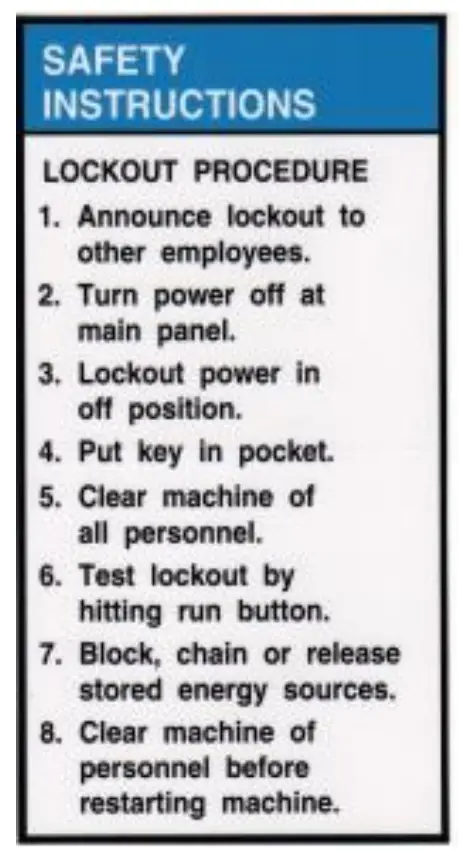 | 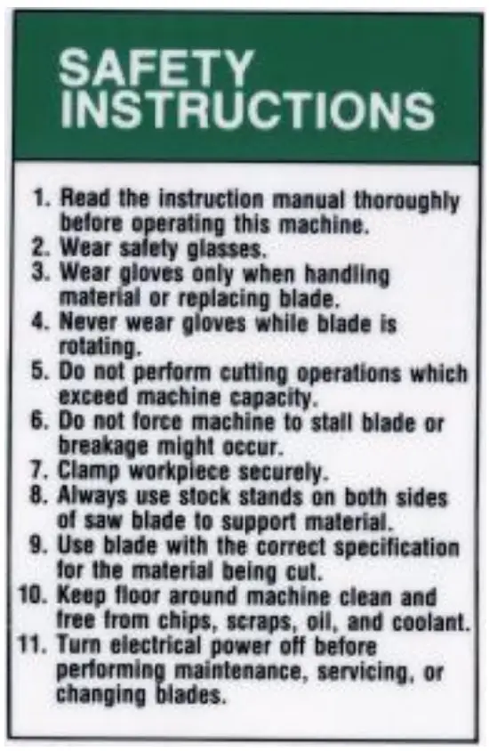 |
| Part # 84395 | Part # 84605 | Part 84605 |
ADJUSTMENTS
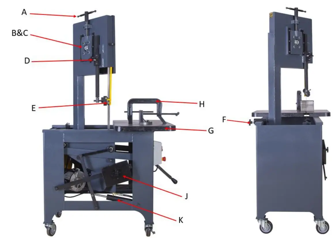
A: BLADE TENSION HANDLE – Used to remove and install saw blade. Also used to set the correct blade tension – Be sure blade is tight.
B&C UPPER BLADE WHEEL CONT ADJUSTMENT – If your saw should get out of adjustment and the blade runs off the wheel or runs back against the lip, loosen the two bottom bolts on the wheel slide (B) Turn the set screw (C) in or out to make the blade run approximately 1/32” away from the lip on the back of the wheel. Tighten the two wheel slide bolts. IMPORTANT: If the blade is allowed to run against the lip on the wheel it will wear the lip off.
D GUIDE BAR LOCK – Used to lock the roll guides in position.
E ROLL GUIDES – Should be adjusted so they clear your work by approximately ½”. This will insure maximum blade rigidity.
F STOP CLAMP – Has two uses: 1) The stop clamp can be set for depth of cut. 2) The stop clamp, if placed behind the neck, will lock the frame in a forward position for contour work.
G ANGLE PLATE – Used to hold stock in place for cutting. Graduations are provided to set angle cuts.
H C-CLAMP – Used mainly for round stock. Flat stock needs no clamping.
J COUNTERWEIGHT – Used to maintain the blade pressure you desire.
K HYDRAULIC CYLINDER – This should be adjusted to allow the frame to travel rapidly but not free fall. This is a safety device and should be kept properly adjusted.
BLADE SELECTION
– For operator convenience, a blade selector chart is located inside the saw cover. It provides recommended blade speeds, required teeth per inch, and minimum cutting radius for various blade widths. The following chart can be used to select the blade needed:
| Thickness of Material | Teeth per Inch |
| Up to 1/8” | 18T |
| 1/8” to 1/4” | 14T |
| 1/4″ to 1/2″ | 10T |
| 1/2″ to 1” | 8T |
| 1” to 3” | 6T-4T |
| 3” to 6” | 4T-6T |
| 6” and longer | 3H |
Blade Speeds: (FPM) & Removal/Install Procedure
– To change blade speeds, bring the frame all the way forward. Lift the motor and move the V-belt to one of the three speeds offered: 70, 140, 270, or 540. Refer to the blade selector chart inside the cover on your SXC for the appropriate speed.
– To remove the blade, release the blade tension handle then remove the blade.
– To install blade, place the blade over the bottom wheel, then on the top wheel. Teeth must point down toward the table. Tighten the blade tension handle enough to hold the blade firmly in place, and the push the blade into the roller guides. Turn the machine on to allow the blade to position itself, and then finish tightening the blade.
Please Note: The most common causes of the SXC not cutting straight are:
- Blade tension is too low.
- Blade is dull or worn on one side.
- Blade was installed upside down. The teeth must point down toward the table.
LUBRICATION
– Gear Box: Your SXC gearbox is filled at the factory. Check the fluid level on arrival, and then check every six months thereafter. Use 90-weight gear lube to maintain fluid level at the fill/check pipe plug.
– Cylinder: Keep the cylinder reservoir 1/2 to 3/4 full. Use light hydraulic oil tore fill.
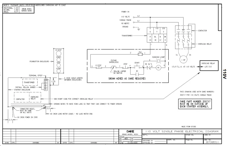
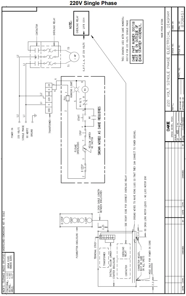
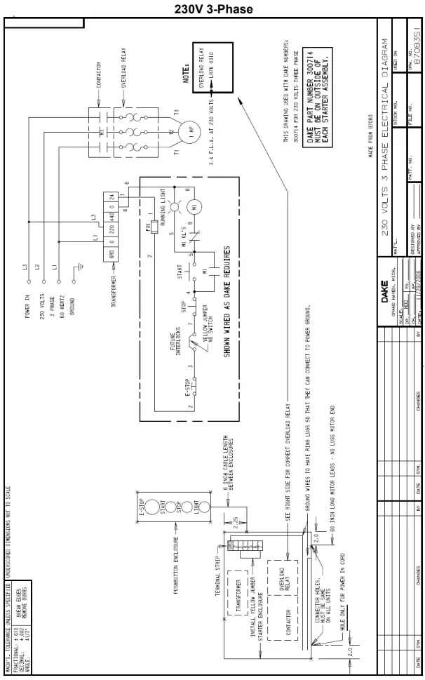
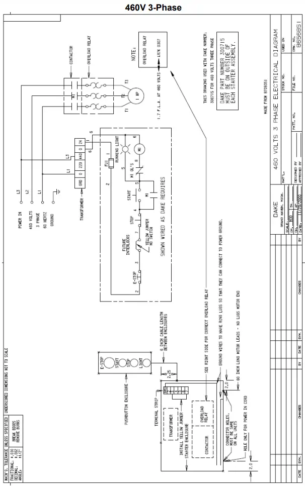
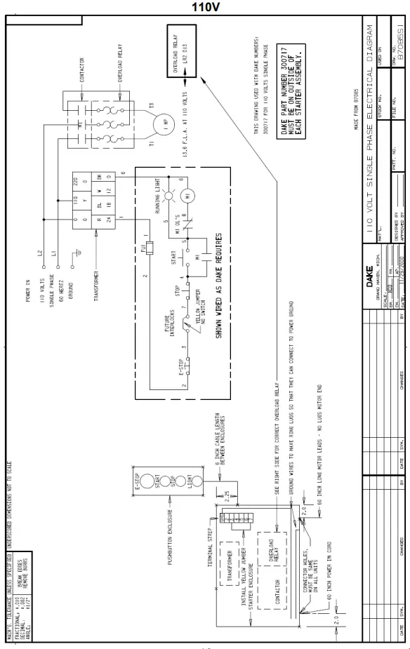
ELECTRICAL DIAGRAMS
EXPLODED VIEWS & PARTS LISTS
| Item | Part Number | Description | Qty |
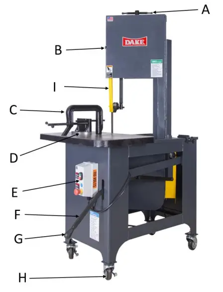
| A | 716716 | Tension Handle Assembly | 1 |
| B | 86747 | Door Latch | 1 |
| C | 716714 | C-Clamp Assembly | 1 |
| D | 716703 | Angle Plate with Pin | 1 |
| E1 | 716764 | New Style Complete Electrical Kit – 1 ph 110 volt | 1 |
| E2 | 716765 | New Style Complete Electrical Kit – 1 ph 220 volt | 1 |
| E3 | 716766 | New Style Complete Electrical Kit – 3 ph 230 volt | 1 |
| E4 | 716767 | New Style Complete Electrical Kit – 3 ph 460 volt | 1 |
| F | 86782 | Return Handle | 1 |
| G | 300450 | Knob, Return Handle | 1 |
| H | 716725 | Caster Set – Optional | 1 |
| I | 87093 | Blade Guard | 1 |
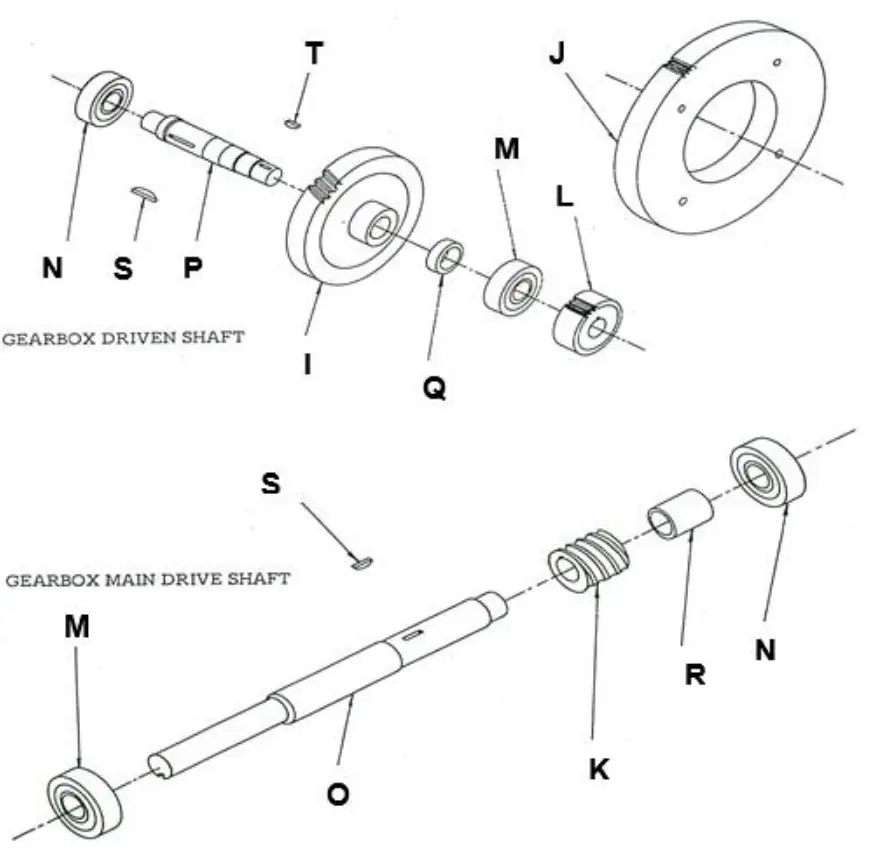
Gear Assembly Parts List
| Item | Part Number | Description | Quantity |
| 716712 | Gearbox Assembly | 1 | |
| 300472 | Bearing, Seal | 2 | |
| 300490 | Gasket, Gearbox | 1 | |
| 300491 | Gasket, Gearbox | 4 | |
| 300589 | Dowel Pin 3/16 x ½ | 2 | |
| 43412 | Screw, Soc Cap | 16 | |
| 43414 | Screw, Soc Cap | 6 | |
| 43590 | Screw, Soc Set | 3 | |
| 86820 | Bearing Cover, Small/hole | 2 | |
| 86821 | Bearing Cover, Small | 2 | |
| 86822 | Gearbox Casting | 1 | |
| 86823 | Cover, Gearbox | 1 | |
| I | 300666 | Gear, Worm 40T Bronze | 1 |
| J | 86784 | 80 Tooth Gear | 1 |
| K | 300456 | Worm, 4-Lead | 1 |
| L | 300646 | 24 Tooth Gear | 1 |
| M | 5072-00 | Bearing, Gearbox | 2 |
| N | 5073-00 | Bearing, Gearbox | 2 |
| O | 86785 | Shaft, Main Drive | 1 |
| P | 86781 | Axle, Gearbox-Short | 1 |
| Q | 86783 | Spacer, Gearbox 1-1/4 | 1 |
| R | 86786 | Spacer, Gearbox | 1 |
| S | 300449 | Key, Woodruff #13 | 2 |
| T | 300451 | Key, Woodruff #5 | 1 |
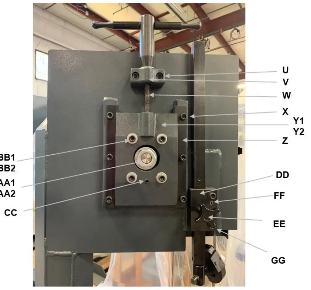
| Item | Part Number | Description | Quantity |
| U | 43450 | Cap Screw | 2 |
| V | 86827 | Wheel Slide Tension Mounting block | 1 |
| W | 10117-00 | Tension Screw | 1 |
| X | 43447 | Cap Screw | 6 |
| Y1 | 86824 | Wheel Slide – External piece | 1 |
| Y2 | 86825 | Wheel Slide Adjustment – Internal piece | 1 |
| Z | 86826 | Rail Wheel Slide | 2 |
| AA1 | 43922 | Nut | 1 |
| AA2 | 43638 | Washer | 1 |
| BB1 | 43452 | Soc Cap Screw 3/8-16 x 1-3/4 | 4 |
| BB2 | 43632 | Washer 5/16” flat | 4 |
| CC | 43591 | Set Screw 3/8-16 x 1 | 1 |
| DD | 86810 | Guide Bar Holder | 1 |
| EE | 300832 | Knob Assembly 1-1/2” | 1 |
| FF | 70287 | Roll pin | 2 |
| GG | 43451 | Cap Screw | 2 |
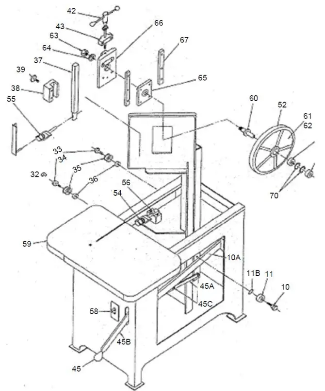
| Item | Part Number | Description | Quantity |
| N/A | 86806B | Contour Insert, Brass, Large (1/2”) | 1 |
| N/A | 86807B | Contour Insert, Brass, Small (1/4”) | – |
| N/A | 86792 | Contour Guides (Casting) | – |
| N/A | 86808 | Contour Insert Holder | – |
| N/A | 86806A | Carbide Inserts, Set of 2 (1/2”) | – |
| N/A | 86807A | Carbide Inserts, Set of 2 (1/4”) | – |
| N/A | 716723 | Counterweight Assembly | 1 |
| N/A | 86832 | Feedweight | 1 |
| N/A | 716709 | Hydraulic Cylinder – OLD STYLE – Machines before 9/27/02. OBSOLETE – Must retrofit new style 716769 | – |
| N/A | 716769 | Hydraulic Cylinder – NEW STYLE with retrofit kit. For machines after 9/27/02. | – |
| N/A | 300505 | Reservoir, Hydraulic Cylinder (1oz.) OLD STYLE | – |
| N/A | 300510 | Reservoir, Hydraulic Cylinder (2oz.) OLD STYLE | – |
| N/A | 716754 | Cylinder Rebuild Kit – OLD STYLE | – |
| N/A | 300598 | Shoulder Bolt, Hydraulic Cylinder | – |
| N/A | 86836 | Eccentric Roller Gravity Feed | 2 |
| 10 | 86816 | Stud Flat Track | 1 |
| 10A | 86852 | Flat Track Rail | 1 |
| 11 | 300471 | Bearing Flat Track W204 | 1 |
| 11A | 86839 | Flat Track Roller Spacer | 1 |
| 32 | 300477 | E-Clip | 1 |
| 33 | 86837 | Stud Lever Weight | 1 |
| 34 | 86819 | Stud Grooved Roller | 1 |
| 35 | 716706 | Roller with Groove & Bearing | 1 |
| 36 | 86838 | Spacer Gravity Feed (3/8) | 2 |
| 37 | 86815 | Guide Support Bar – STD | – |
| 37 | 86817 | Guide Support Bar – SXC, XC (Current) | 1 |
| 38 | 86810 | Guide Bar Holder | 1 |
| 39 | 300832 | Guide Bar Lock Knob | 2 |
| 40 | 86813 | Swivel Guide Bar Support | 1 |
| 42 | 716716 | Tension Handle Assembly | 1 |
| 43 | 86827 | Pillow Block | 1 |
| 44 | 86828 | Tension Handle Body | 1 |
| 44A | 43634 | Tension Handle Washer | 1 |
| 44B | 10117-00 | Tension Screw | 1 |
| 45 | 300450 | Return Handle Knob | 1 |
| 45A | 86841 | Return Handle Link | 1 |
| 45B | 86782 | Return Handle | 1 |
| 45C | 43777 | Return Handle Shoulder Bolt (1/2 x 1/2) | 3 |
| 45D | 24565 | Return Handle Axle Bolt (1/2-13 x 3” SHCS) | – |
| 45E | 86839 | Return Handle Spacer (1/4) | 2 |
| N/A | 86798 | Motor Mounting Axle | 1 |
| N/A | 86800 | Motor Mounting Block | 2 |
| 52 | 300459 | Band, Blade Wheel | 2 |
| 53 | 10025-01 | Roll Guide Bearing | 4 |
| 54 | 87087 | Roll Guide (1”) | – |
| 54 | 86809 | Roll Guide (3/4”) | 4 |
| 54A | 716717 | Upper/Lower Roll Guide Assembly (Includes items 53, 54 (3/4”), 55, 56A, and screw) | 1 |
| 55 | 86811 | Guide Roller Holder | 2 |
| 56 | 86805 | Guide Roller Pillow Block | 1 |
| 56A | 86814 | Eccentric Lower Guide | 2 |
| 56B | 86812 | Pin, Lower Guide Rolls | – |
| 57 | 86791 | Frame Stop | 1 |
| 58 | 300832 | Stop Weight Knob | 1 |
| 59 | 86796 | Work Table | 1 |
| 60 | 86803 | Axle, Upper/Lower Wheel | 2 |
| 62 | 86795 | Blade Wheel | 2 |
| 63 | 78650 | Washer | 2 |
| 64 | 300651 | Nut | 2 |
| 65 | 300693 | Wheel Bearing (6205) | 4 |
| 66 | 86824 | Wheel Slide | 1 |
| 67 | 86826 | Rail, Wheel Slide | 2 |
| 68 | 86825 | Wheel Slide Adjustment | 1 |
| 69 | 86804 | Stud, Upper/Lower Wheel | 2 |
| 70 | 300466 | Retaining Ring, Blade Wheel | – |
| N/A | 87065A | Wheel Guard | 1 |
| N/A | 300685 | Pulley Guard Assembly | 1 |
| N/A | 300522 | V-Belt | 1 |
| N/A | 43632 | Washer, Angle Plate | 1 |
| N/A | 86835 | Lever Link Weight | 1 |
ORDER INFORMATION
– Please contact factory for current prices
– Parts are available for direct purchase from Dake or through a distributor. When placing a parts order, you will need to provide the part number, name of part, and model number. All parts shipped F.O.B. Factory in Grand Haven, MI.
– If a customer has any questions or concerns regarding a Dake product that was purchased, please email customer service at [email protected]