systemair Multilingual Fans Instruction Manual
Safety Information
This machinery must not be put into operation prior to reading mounting instructions and safety information.
All fans are intended for transportation of air in air handling systems. If installed in non-heated rooms, the fan casing has to be insulated in order to avoid condensation. They are meant for use once built into machinery or ducted systems and after a protection grid has been installed. (EN ISO 13857). Fans with duct connections must be connected to ducts on both sides (inlet/outlet). No moving parts shall be accessible after installation. The fans are not to be used in hazardous environments or connected to flue ducts. The fans must not be installed outdoors, (with exception of roof fans and fans with, for this purpose, with corresponding IP class). Fans installed without insulation in non-heated areas bear a risk a risk of condensation. Safety accessories (i.e. motor protection, safety grille) may not be removed, short-circuited or disconnected. Roof fans are exclusively intended for extract air applications.
This appliance can be used by children aged from 8 years and above and persons with reduced physical, sensory or mental capabilities or lack of experience and knowledge if they have been given supervision or instruction concerning use of the appliance in a safe way and understand the hazards involved. Children shall not play with the appliance. Cleaning and user maintenance shall not be made by children without supervision.
Precautions must be taken to prevent the backflow of exhaust gases from flues from other appliances installed in the same room, which are fired by gas or other fuels.
The appliance must be connected to a mains circuit breaker in the fixed installation.
Install a circuit breaker in the permanent electrical installation, with a contact opening of at least 3 mm at each pole.
CAUTION!
- Before servicing or maintenance, switch off power, (all-pole circuit breaker), and make sure the impeller has come to standstill.
- The fans can have sharp edges and corners, which may cause injuries.
- Be careful when opening the fans service hatches (swing-out), the fan and motor assembled on the hatch is relatively heavy.
- Electrical reset.
Transportation and Storage All fans are packaged at the factory to withstand normal transport handling. When handling the goods use suitable lifting equipment in order to avoid damage to fans and personnel. Do not lift the fans by the connecting cable, connection box, impeller or inlet cone. Avoid blows and shock loads. Store the fans in a dry place protected from weather and dirt until final installation.
Installation
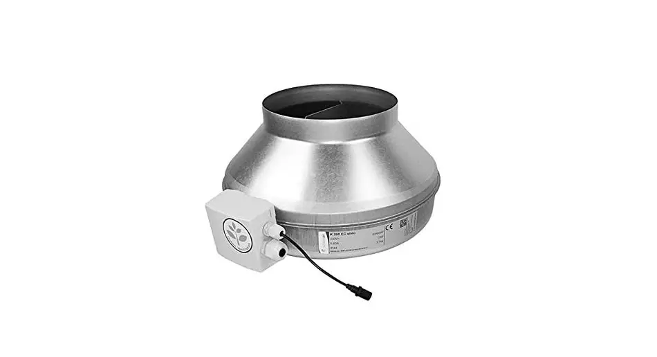
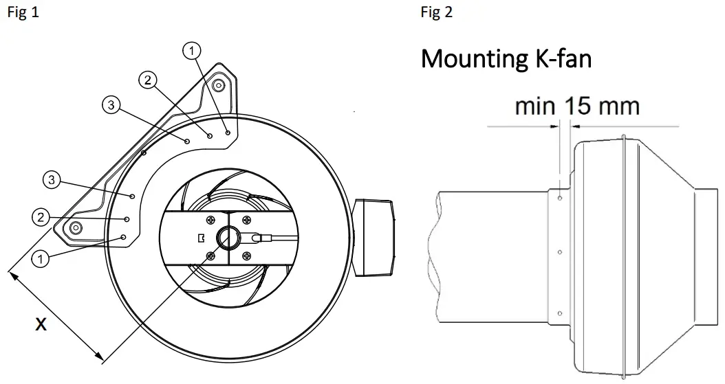
Refer to Safety information above. Installation, electrical connection and commissioning are only to be carried out by authorised personnel and in accordance with requirements and demands. Electrical connections are made according to the wiring diagram in the terminal box, markings on terminal blocks or on cable. All 3 phase fans are delivered from factory in 400V 3~ connection. Seal any empty cable glands with dummy plugs. The K-fan must be installed with the connection box at the top of the unit ± 90 degrees. If permanent installation is carried out using cables with diameter 12-14 mm, the entrance bush must be replaced (applies to type K, KV, RVF and KVK 125/160). To preserve IP44 the RS fans must not be mounted with the connection box/motor plate upwards (Fig.1). When installing KBT in high level of moisture (e.g. washing area), sufficient drainage to the fan is crucial. This is to prevent freezing damage to the fan in case of low temperatures.
Fans with thermal contacts with external leads (TK) must always be connected to external motor protection. Assemble the fan in the direction of airflow (see arrow on unit). The fan must be installed to ensure that any vibration is not transmitted via the duct system or frame of the building. (Suitable accessories such as fast clamps and diffusers are available). Make sure the assembly of the fan is firmly fixed and stable (Fig 3). The fan can be mounted in any direction unless stated otherwise. The fans must be installed to ensure that service and maintenance can be performed easily and safely. Installing silencers (available as an accessory) can reduce disturbing noise.
When using frequency regulation an all pole sinus filter must be mounted between motor and frequency controller (version all poles: phase-to-phase, phase to earth). Fans are meant for continuous use within the temperature range stated.
Fans with manual thermal contacts (reset by disconnecting the power, motor protection SP1), must be taken into consideration when connecting surrounding equipment with automatic on/off function. Recomended wiring for KT fans (Fig 2).
Operation
Before initial operation, check the following:
- Electrical connection has been properly completed.
- Protective conductor has been connected.
- Motor protection installed.
- Safety devices in place (protection grid)
- Leftover installation materials and foreign materials have been removed from the casing.
When putting into operation, check the following:
- Connection data corresponds to the specifications on the nameplate: Maximum voltage +6%, -10%, according to IEC 38. Rated current must not be exceeded with more than 5% at rated voltage.
CAUTION! When speed regulating by reducing the voltage the motor current may exceed the rated current at a lower voltage. In this case, the motor windings are protected by the thermal contact. The minimum static fall of pressure must be observed.
- That the motor protection is functional. The direction of rotation should correspond to direction-of-rotation arrow (3 phase).
- Smoothness of motor operation, (no abnormal noises).
- Failure to connect the thermal motor protection will result in all warranties being null and void.
- TFE 220 is adapted to continuous operation.
Sound levels exceeding 70 dB(A) may occur depending on model and size (see online catalogue at www.systemair.com for detailed information).
Maintenance, Service and Repair
Prior to maintenance, service or repair, ensure that:
- Power supply is interrupted (all-pole circuit breaker).
- Fan impeller has come to a complete standstill
- Observe personnel safety regulations!
- Should the supply cable be damaged, it must be replaced by the manufacturer, its service agent or similarly qualified persons in order to avoid a hazard.
The fan should be cleaned when necessary, at least 1/year to avoid imbalance and unnecessary damage to the bearings. A filter will prolong the time interval between each cleaning of the fan. (It is sometimes recommended to install a filter guard). The fan bearings are maintenance free and should only be replaced if damaged. Do not use a highpressure cleaner (steam jet) when cleaning the fan. Ensure that the fan impeller’s balance weights are not moved or the fan impeller distorted. Listen for abnormal operating noise.
Resetting of the thermal trips
Manual thermal trips (SP1) are reset by disconnecting the mains for approx. 10-20 min.
Fans with external leads for thermal trips (TK) are reset from the external motor protection. This protection may not have automatic resetting.
Make sure the fan has not been blocked or that the motor protection has tripped. Contact the supplier if the motor does not start after controlling and/or resetting the motor protection.
Disposal and recycling
Residential products with this symbol at the nameplate are compliant to the WEEE directive. When disposing the unit, follow your local rules and regulations.
This product packing materials are recyclable and can be reused. Do not dispose in household waste.
For labelled components such as for example fans, the disassembly instructions can be found on the component manufacturer’s homepage.
Wiring diagram
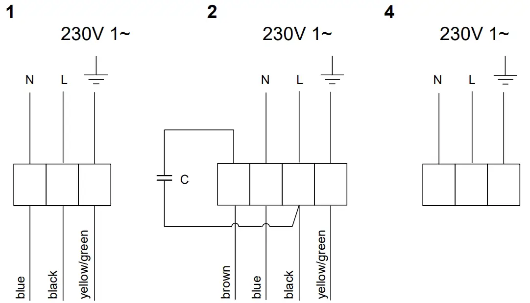

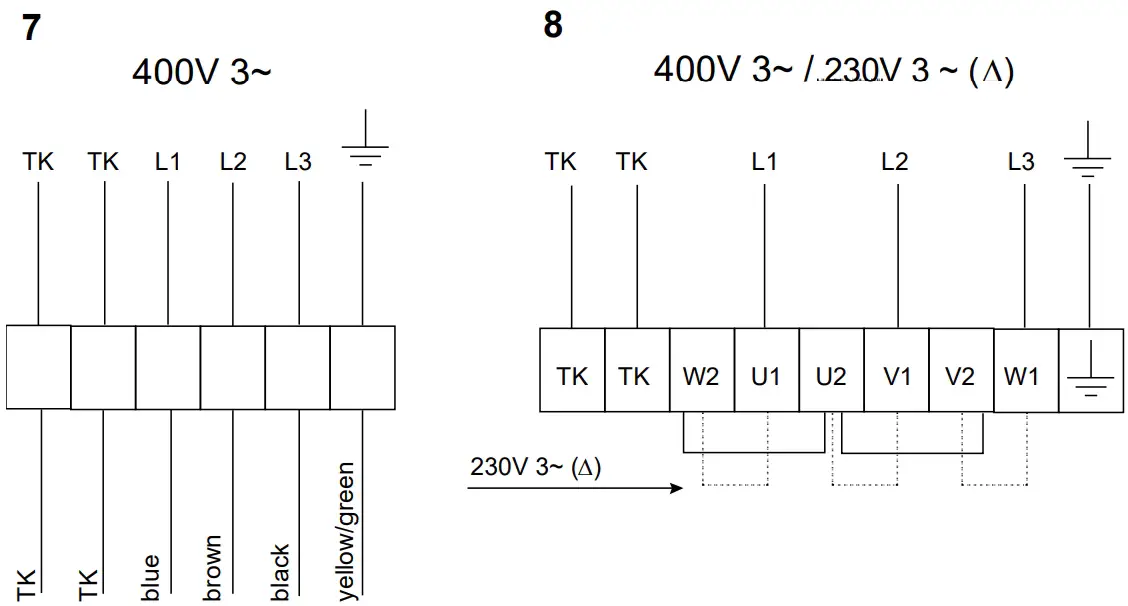
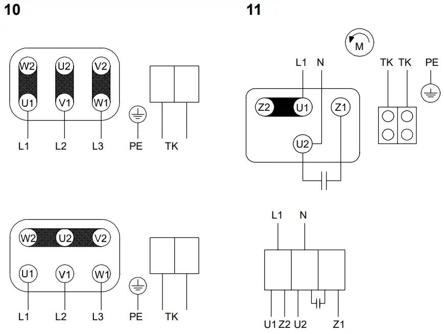
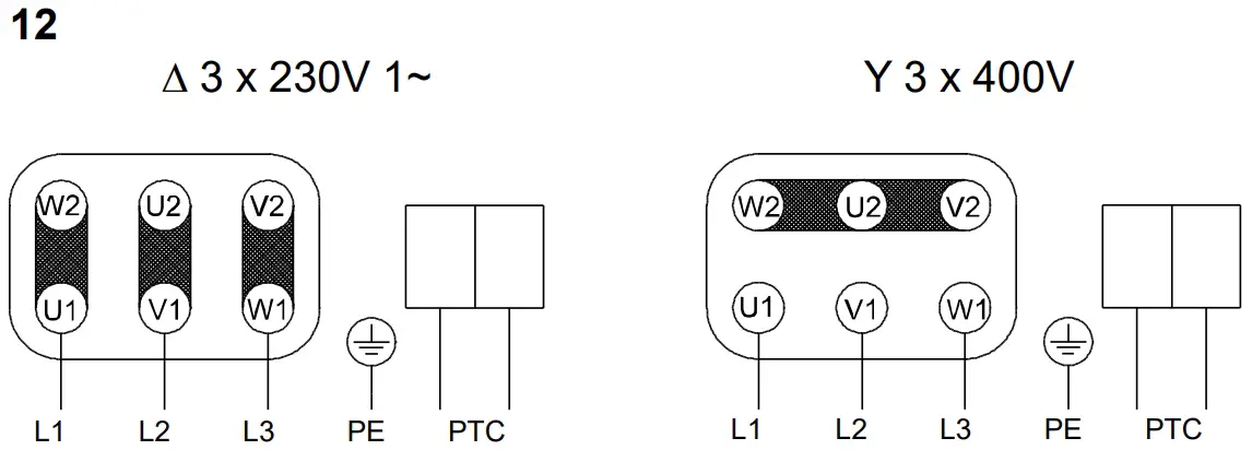
| Fan type | Diagram | Fan type | Diagram |
| CE 140 only | 2 | KVK DUO | 5 |
| CE 200 only | 5 | KVK Silent 100-160 | 4 |
| CE-series (all other sizes) | 6 | KVK Slim 100-160 | 2 |
| CKS-560-3 | 8 | KVKE-series | 4 |
| CT 200 | 7 | KVO 200-315 | 2 |
| a-series (all other sizes) | 8 | KVO 3 | 8 |
| K/KV 100/125 M | 1 | KVO 355-400 | 6 |
| K/KV other sizes | 2 | prio 450-500 | 8 |
| KBT 160DV, 200DV | 10 | RS 30-15 to 50-25 | 2 |
| KBT 160E4-250E4 | 11 | RSI-series 1 | 6 |
| KBT 250D4 IE2-280D41E2 | 12 | RSI-series 60-35 to 100-50, 3 | 8 |
| KD 200L to 355S | 2 | RS-series 1— (all other sizes) | 6 |
| KDRD-series | 8 | RS-series 80-35 to 100-50, 3 | 8 |
| KDRE-series | 6 | RVF 100M | 1 |
| KD-series 1 (all other sizes) | 6 | TFE 220 | 2 |
| KE 40-20 only | 5 | TFER 125M only | 1 |
| KE-series (all other sizes) | 6 | TFER 125XL-315 | 2 |
| KT 40-20 only | 7 | TFSK 125M — 315L | 1 |
| KT-series (all other sizes) | 8 | TFSR 125M – 315L | 1 |
| KVK 125-160 | 2 | TOE-series | 6 |
| KVK 200-250 | 5 | TOV-series | 8 |
Figures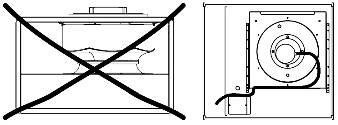
| Type | Screw | X (mm) |
| K 100M | 3 | 112,5 |
| K 125 M | 3 | 112,5 |
| K 100/125 XL | 1 | 124,5 |
| K 150/160 M | 2 | 148,5 |
| K 3.50/iso XL | 1 + 3 | 174,5 |
| K 200/250 M | 1 + 2 | 183,5 |
| K 200/250 L | 1 + 2 | 183,5 |
| K 315/12 M/L | 1 + 2 | 222 |
EU Declaration of Conformity
 Manufacturer
Systemair Sverige AB
Industrivägen 3 SE-73930 Skinnskatteberg,
Sweden
Office: +46 222 440 00 Fax: +46 222 440 99
www.systemair.com
Hereby confirms that the following products, including Sileo versions, comply with all applicable requirements in the following directives and regulations.
Duct fans with circular connection:
K 100-315L, KD 200 L1-400, prio 450-500,
KVK Slim 100-160
Insulated duct fans with circular connection:
KVK Silent 100-160, KVK 125-250, KVK DUO
125-500
Wall mounted fans with circular connection:
KV 100M-315L, RVF 100M
Duct fans with rectangular connection:
KE/KT40-20-4 – 100-50-8,
RS/RSI 30-15L – 100-50L3, KDRE/KDRD 45-70
Roof fans with circular or square connection:
TFSR/TFSK 125M-315L, TFE 220S/M,
TOE/TOV 355-4 – 560-4
Kitchen fans:
Essvent S/L, KFB140S/L
Radial fans:
CE 140S-125, CE 140L-125, CE 140M-160, CE 140L-160, CT 225-4, CT 250-4, CT 280-4, CT 315-4, CT 355-4, CKS 560-3
Thermo fans:
KBT 160DV, 200DV, KBT 160E4-250E4,
KBT 250D4 IE2-280D4 IE2
(The declaration applies only to product in the condition it was delivered in and installed in the facility in accordance with the included installation instructions. The insurance does not cover components that are added or actions carried out subsequently on the product).
Machinery Directive 2006/42/EC
Low Voltage Directive 2014/35/EC
EMC Directive 2014/30/EC
RoHS Directive 2011/65/EU, 2015/863/EU
(Residential units)
Ecodesign Directive 2009/125/EC
327/2011 Requirements for fans above 125W
1253/2014 Requirements for ventilation units above 30W
1254/2014 Requirements for energy labeling of residential ventilation units
The following harmonized standards are applied in applicable parts:
EN ISO 12100:2010
Safety of machinery – General principles for design – Risk assessment and risk reduction.
EN 13857
Safety of machinery – Safety distances to prevent hazard zones being reached by upper or lower limbs.
EN 60 335-1
Household and similar electrical appliances –
Safety Part 1: General requirements.
EN 60 335-2-80
Household and similar electrical appliances – Safety – Part 2-80: Particular requirements for fans.
EN 62233
Measurement methods for electromagnetic fields of household appliances and similar apparatus with regard to human exposure.
EN 50 106:2007
Safety of household and similar appliances – Particular rules for routine tests referring to appliances under the scope of EN 60 335-1 and EN 60967.
EN 60529
Degrees of protection provided by enclosures (IP Code).
EN 60 204-1
Safety of machinery – Electrical equipment of machines – Part 1: General requirements.
EN 61000-6-2
Electromagnetic compatibility (EMC) – Part 6-2: Generic standards – Immunity for industrial environments.
EN 61000-6-3
Electromagnetic compatibility (EMC) – Part 6-3:
Generic standards – Emission standards for residential, commercial and light-industrial environments.
EN ISO 5801
Fans – Performance testing using standardized airways.
EN 13142
Ventilation for builings – Components/Products for residential ventilation – required and optional performance characterisics.
EN 14121
Aluminium and aluminium alloys – Sheet, strip and plate for electrotechnical applications. Skinnskattberg 2019-12-13
![]()
Sofia Rask
Managing Director
Support
Systemair Sverige AB
Industrivägen 3
739 30 Skinnskatteberg
Phone +46 222 440 00
Fax +46 222 440 99
www.systemair.com