
TROTEC HG125 Hygrostat User Manual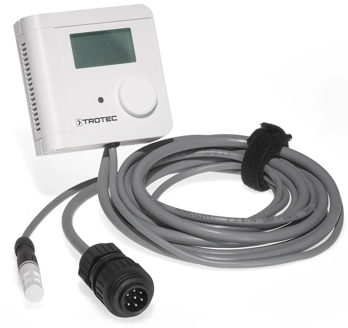
Notes regarding the operating manual
Legal notice
This release replaces all previous versions. No part of this publication may be reproduced without written permission from Trotec GmbH. The same applies for electronically processing, duplicating or spreading the publication. Subject to technical changes. All rights reserved. Trademarks are used without guarantee that they may be used freely and primarily following the spelling of the manufacturer. Product names are registered.
Changes to construction in the interests of constant improvements to the product, as well as changes to the shape and colour are reserved.
The scope of delivery may vary from product images. This document was created with all due care.
Trotec GmbH accepts no liability whatsoever for possible mistakes or omissions.
© Trotec GmbH
Symbols
The current version of the operating manual can be found at: HG 125 electronic
ESD protection instructions
The devices contain components which can be damaged by the effects of electrical fields or by charge equalisation when touched.
The following safety measures must be observed when opening the device for maintenance or for modifying the connection:
- Before opening the housing, establish potential equalisation between you and your environment.
- Make sure that this potential equalisation is maintained when working while the housing is open.
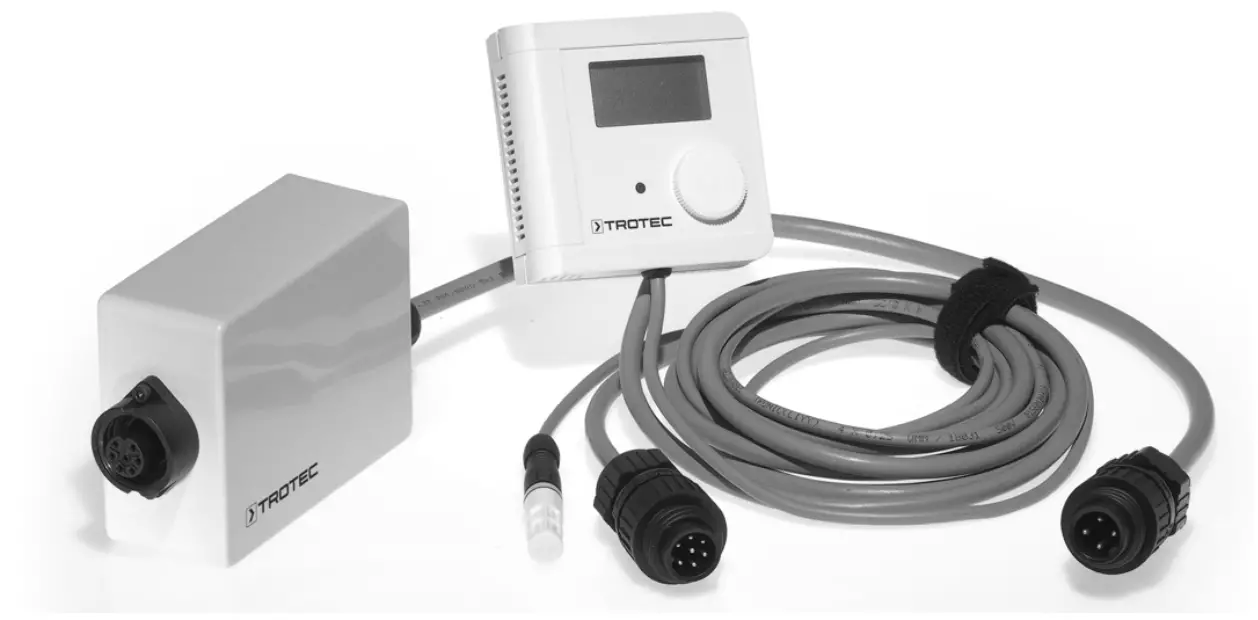
Device description
Easy to install
- 5 m cable length for remote probe
- 2 potential-free switching outputs, configurable as NC or NO contacts
- 2 nominal values and switching hystereses, independently configurable
- Display of current relay switching states
- 2 continuous signal outputs (0…10 V), for relative humidity and temperature
- Pluggable and exchangeable calibrated measuring probe
- Alternating display of relative humidity and temperature
Application
- Detrimental influences
Aggressive media containing solvents can cause measuring errors and failure, depending on the type and concentration. For instance, deposits forming a water repellent film on the sensor element (resin aerosols, paint aerosols, smoke substances etc.) are damaging.
Assembly
- Position
The place of assembly of the external sensor must be chosen so as to ensure a representative humidity and temperature measurement. Do not install near heat sources such as radiators, doors, window and outer walls.
Avoid direct sunlight. - Connection
The device is preconfigured and preassembled upon delivery. Any modifications of the hygrostat must be carried out by expert staff. The housing contains sensitive components. When opening the housing, observe the ESD protection instructions (see 01. ESD protection instructions). Supply lines to the device as well as the sensor cable must not be installed parallel to strong electromagnetic fields. In case of potential overvoltage, install appropriate overvoltage protection devices.
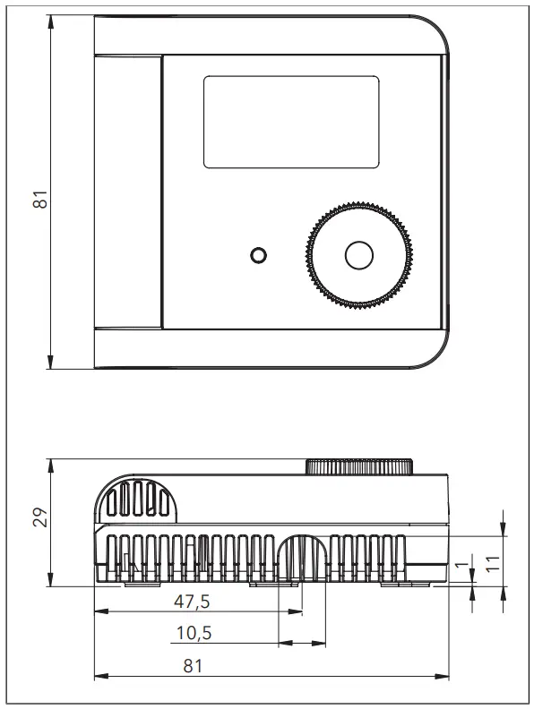
Dimension drawings
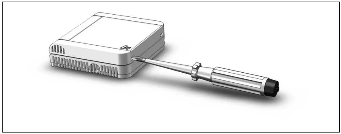
Opening the housing (schematic diagram)
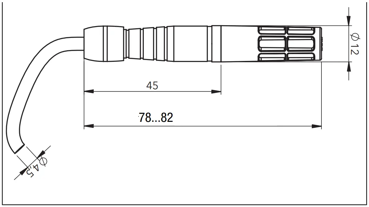
Dimension drawing of the cable sensor
Configuration instructions
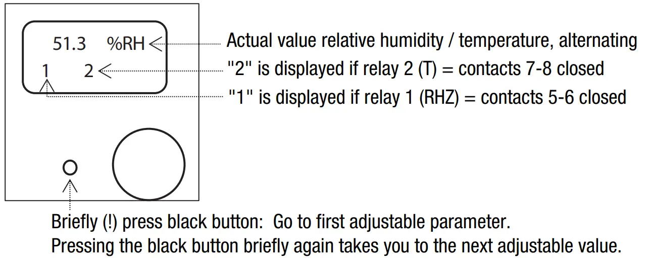
Operating mode
Configuration mode
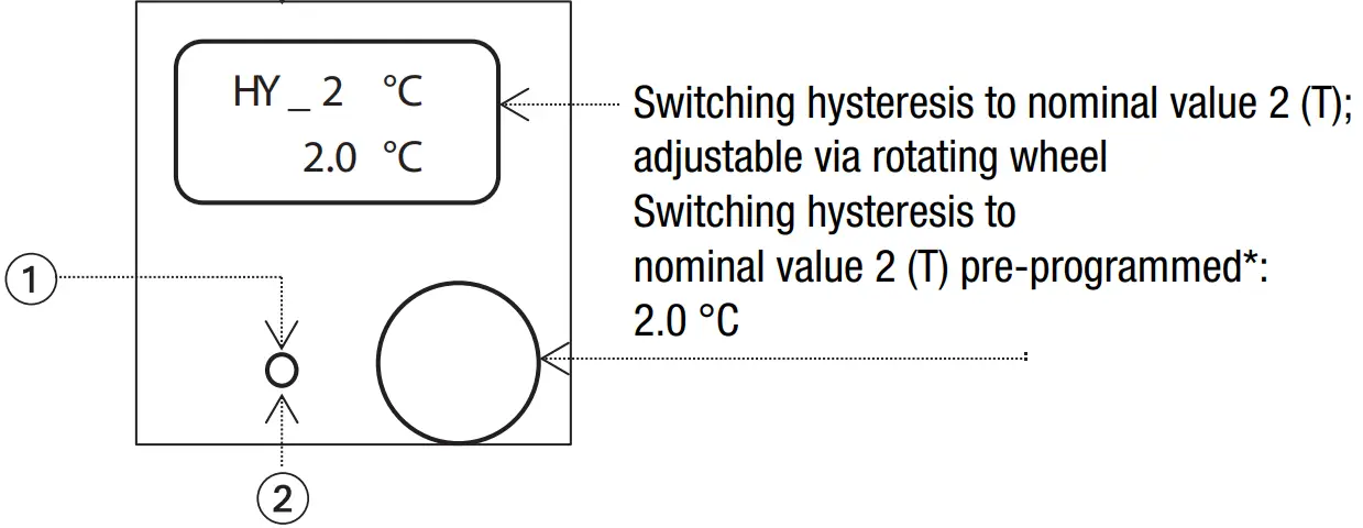
CONFIGURATION:
- Press black button for a long time (>3s): adopt modified value (display “Store”)
- Briefly (!) press black button: do not adopt the modified value (display “_ESC” = leave, return to operating mode)
If no setting or change is made over a longer period (approx. 30s), the menu will automatically return to operating mode via “_ESC”. All settings and changes previously made are not adopted in this case.
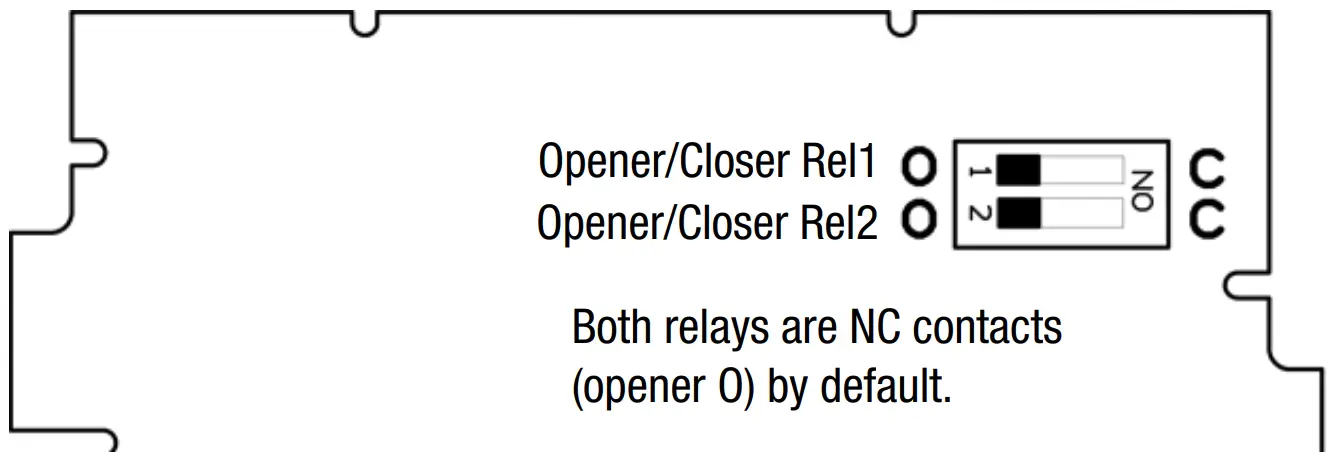
Setting of relays
Setting of relay 1 and 2 as NC contact (opener) or NO contact (closer).
| DIP switch set to | current measured value | |
| < nominal value – switching hystereses / 2 | > nominal value + switching hystereses / 2 | |
| C (closer) | relay = open | relay = closed |
| O (opener) | relay = closed | relay = open |
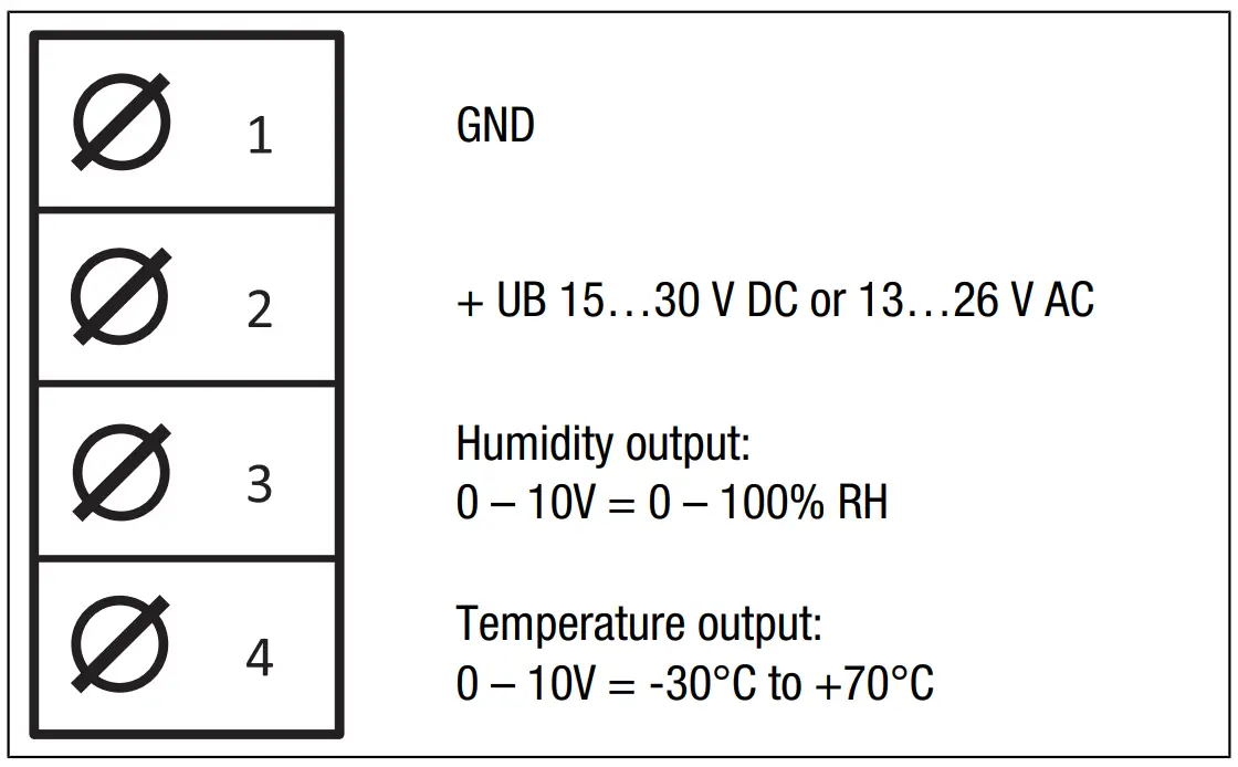
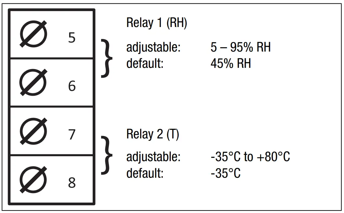
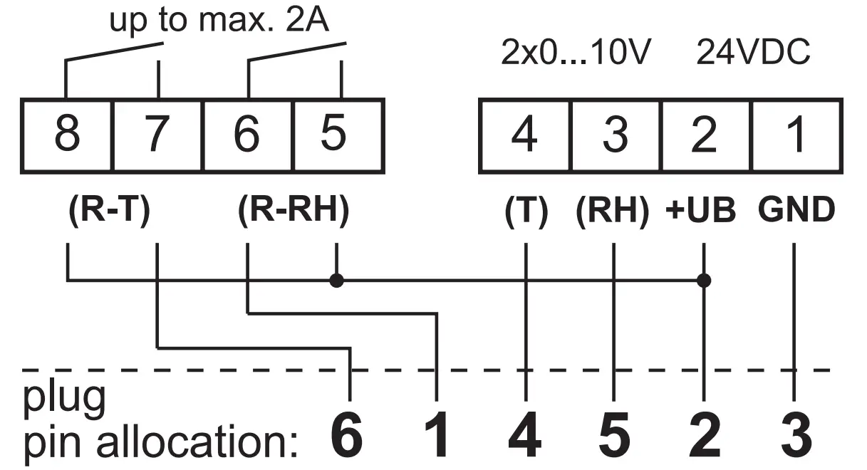
Connection diagrams
Technical data
HG125 ![]()
610.000.2042
![]()
2 x Relay output (R-RH) (R-T)
Analog output 1 Rel. Humidity (RH): 0….100%RH
Analog output2 Temperature (T): -30…+70°C
Humidity (RH
| Measuring range humidity output | 0…100 % RH |
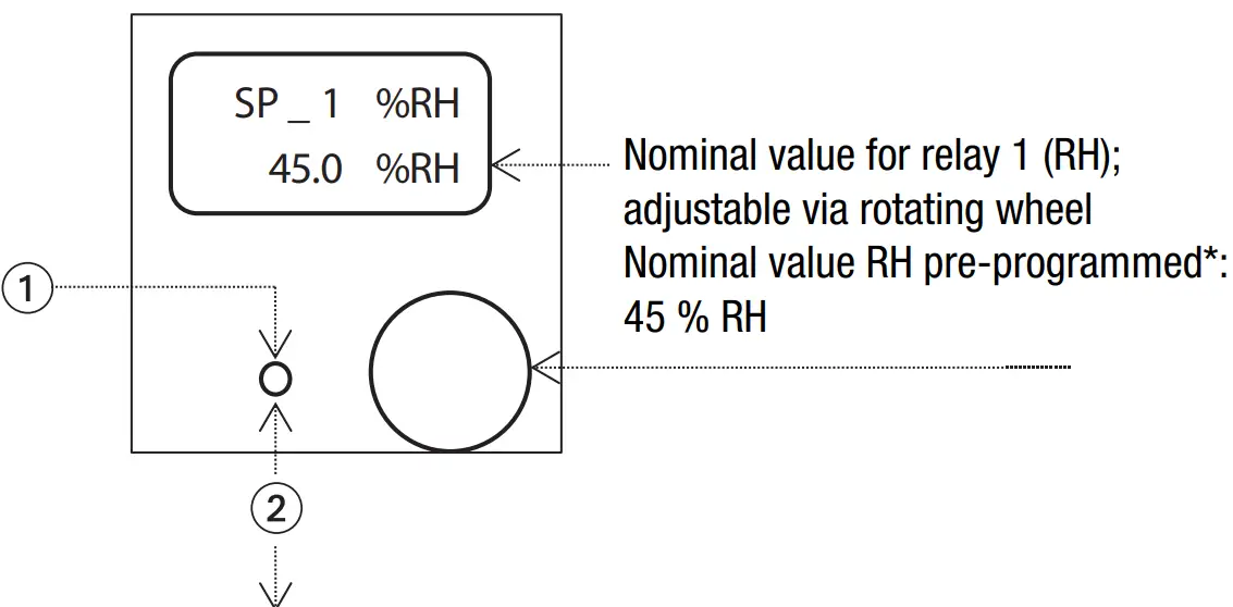
| Setting range relay 1 (RH) default | 5…95 % RH 45 % RH |
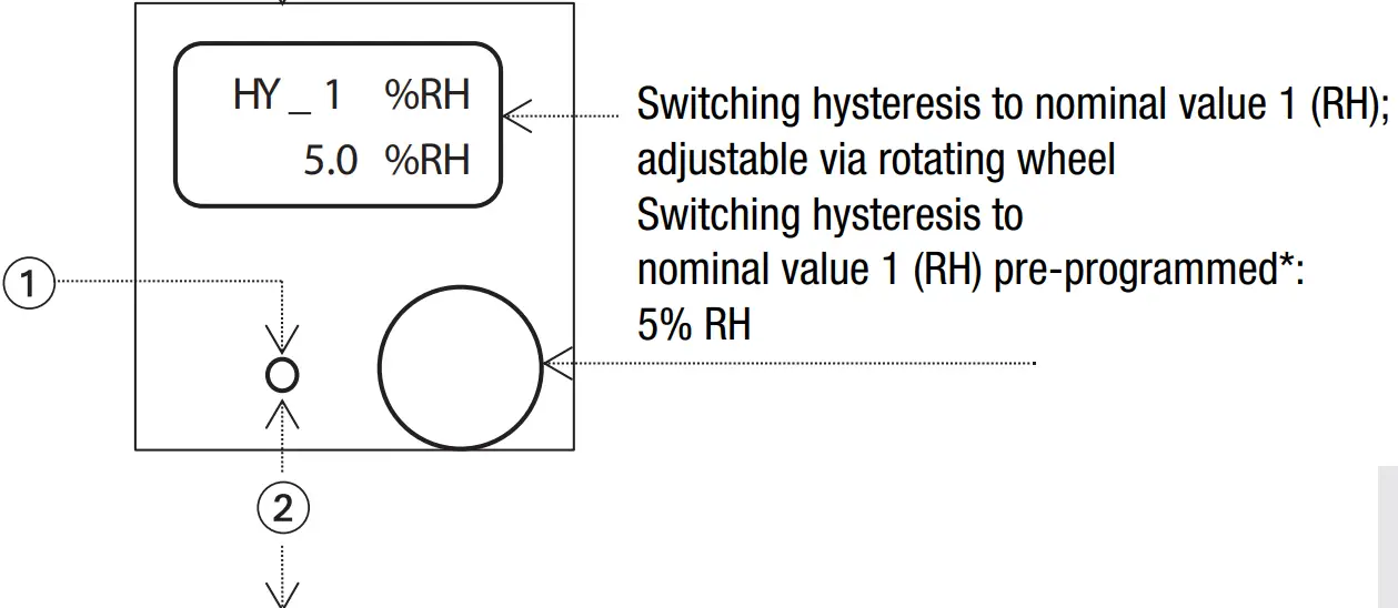
| Setting range of switching hysteresis RH default | 0.5…9 % RH 5 % RH (+/- 2.5 % RH) |
| Measurement uncertainty 10…90 % RH at 25°C max. 0…10 % RH and 90…100 % RH ( at 25 °C Long term stability Hysteresis Typ. temperature influence at 25 °C | ≤ ±2 % RH additionally ≤ ±0.2 % RH / % RH ≤ 0.5 % RH/a ≤ ±1 % RH ±0.05 % RH/K |
Temperature (T)
| Analog temperature output | -30…+70 °C 0…10 V |
| Measurement uncertainty at 23 °C | typ. ±0.2 K |
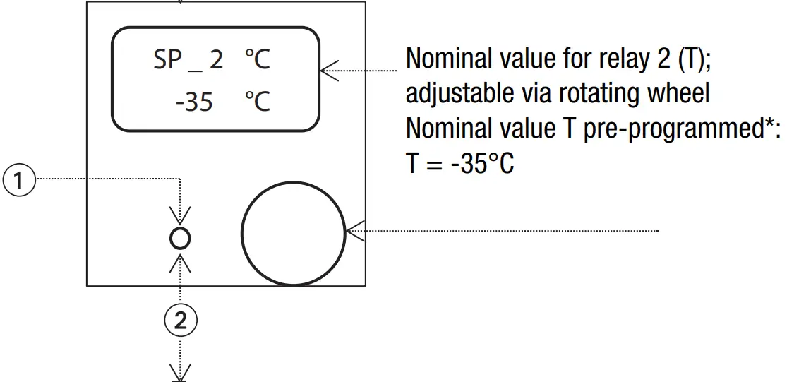
| Setting range relay 2 (T) default | -35 °C to +80 °C -35 °C |
| Setting range of switching hysteresis T default | 0.1 °C to +10 °C 2 K (+/- 1 °C) |
Electrical data
| Switching outputs: | 2 relay contacts, potential-free |
| Setting NC / NO contact default | via DIP switch NC contact (opener O) |
| Switching voltage relay contact | ≤ 48V DC / AC |
| Switching capacity | ≤ 60 W / 62.5 VA |
| Power factor | ≥ 0.9 |
| Switching cycles (at Pmax) | > 105 |
| Switching current | ≤ 2A |
| Continuous output rel. humidity | 0…10 V DC |
| Continuous output temperature | 0…10 V DC |
| Supply voltage | 15…30 V DC 13…26 V AC |
| Self-consumption | ≤ 30 mA |
| Applied standards | EN 61326-1 |
General data
| Measuring medium | pressureless, non- condensing, non- aggressive air |
| Operating temperature housing | -30…+80 °C |
| Operating temperature cable sensor | -40…+85 °C |
| Storage temperature | -40…+85 °C |
| Electrical contact of terminals Wire cross-section of each terminal Cable diameter Surface-mounted cable Flush-mounted cable | max. 1.5 mm² max. 1 x Ø 6.5 mm or 2 x Ø 4.5 mm see: User information on page 5 |
| Type of protection of cable sensor with membrane filter ZE08 (standard equipment) with PTFE sinter filter ZE05 (optional) | IP30 IP65 |
| Type of protection of housing | IP 30D |
| Protection class | III |
| Housing material | ABS |
| Housing colour | signal white similar to RAL 9003 |
| Digital display | 2-line |
Note
The information contained herein reflects our current state of knowledge and is meant to provide information on our products and their possible applications. Thus, it is not intended to warrant specific properties of the products or their suitability for a particular application. Experience shows that the use of the devices covers a broad range including the most diverse conditions and loads. We cannot assess every individual case.
The customer or user must examine the suitability of the devices. Any existing industrial property rights must be taken into consideration. We guarantee perfect quality within the framework of our General Terms of Delivery. Subject to changes.
Optional accessories
Adapter transformer HG 24 V
When using the hygrostat in combination with Trotec dehumidifiers with 4-pin DIN socket, the optionally available adapter transformer is required in addition.
Article no. 6.100.002.043
Trotec GmbH
Grebbener Str. 7 D52525 Heinsberg![]() +49 2452 962-400
+49 2452 962-400![]() +49 2452 962-200
+49 2452 962-200
[email protected]
www.trotec.com
![]()


