![]()
Dust Collector
Instruction Manual
Document No. CMN311-002
MODELS
CSC-1200TP ( 200- 2 3 0V single phase)
CSC-1500TP ( 2 0 0 – 2 3 0V single phase)
CSC-2400TP ( 2 0 0 – 2 3 0V single phase)
CSC-1200TP Dust Collector
![]() Please understand well the contents of “Cautions on Product Use” of Instruction Manual (hereinafter referred to as “this manual”), and operate it after often reading this manual.
Please understand well the contents of “Cautions on Product Use” of Instruction Manual (hereinafter referred to as “this manual”), and operate it after often reading this manual.
Please keep this manual carefully to be able to use it at any time.
CHIKO AIRTEC CO., LTD.
We greatly appreciate that you have purchased our CSC Series.
CHIKO AIRTEC CO., LTD. is working to achieve clean air with compact equipment while utilizing “air technology” effectively.
The CSC Series is an energy-saving-type clean box that realizes “air technology” in a compact body.
Please read this instruction manual thoroughly and handle this CSC Series machine correctly so that you can use it safely for a long time and enjoy its full performance.
About Notation
| Notation | Description |
| IMPORTANT | The information for fully exhibiting the function of this machine and the information for preventing damage to this machine are indicated. |
| NOTE | The information which is consulted is indicated. |
| 1. 2. 3. ・・・ | The operating procedure is indicated. |
| The reference destination is indicated. |
Copyrights
- CHIKO AIRTEC CO., LTD. owns the copyright of this manual.
- Unauthorized reproduction or copying of part or all of the content of this manual is strictly prohibited.
- The contents of this manual are to change without notice.
© 2022 CHIKO AIRTEC CO.,LTD.
Chapter 1 Product Usage Precautions
1.1 Safety Notations
This instruction manual describes usage precautions with the below listed symbols.
Be sure to read the instructions.
| Symbol | Meaning |
| Indicates a hazardous situation which, if not avoided, could result in personal death or serious injury. | |
| Indicates a hazardous situation which, if not avoided, could result personal injury or damage to the device. | |
| Indicates a prohibited action (which MUST NOT be done). | |
| Indicates a mandatory action (which MUST be done). |
1.2 Precautions for Transport, Storage, and Relocation
| • Transportation must be done using at least two people. Injury may result due to tumbling hazard. | ||
| • Relocation and storage must be done in a safe location within the temperature range of -10°C to 60°C at relative humidity of 80% or less. |
1.3 Precautions for Installation
| • Do not install the device in or around an area with flammable, explosive, or corrosive mist, smoke, or gases. | ||
| • This device is designed for installation in a cleanroom or a clean factory. Avoid installation in other areas, such as outdoors. • Ensure a wide suction port. If the device is used continuously with a narrow suction port (i.e., at high pressure), the motor may become hot as it cannot be cooled. | ||
| • Install the device in a horizontal, vibration-free location as it contains rotating equipment. • Install the device at normal temperature (ambient temperature 0°C to 40°C, at humidity 80% or less) without dew condensation. High temperature or dew condensation may cause failure of electrical components or electric shock. • Beware that suction ambient temperature (temperature around the dust to be collected) is low enough, because otherwise the motor may lead to performance reduction or failure. • Provide a sufficient space for the exhaust port (at least 100 mm from the exhaust port). If the exhaust port is blocked, the proper suction power cannot be delivered. Furthermore, sufficient cooling is not provided in the box, causing burnout of the motor or failure of electrical components. • The installation site should be at an altitude of 1,000 m or less. |
1.4 Precautions for Operation
| • Do not suck the following substances: Flammable substances … Gasoline, thinner, benzine, kerosene, paints, etc. Explosive dusts ……….. Aluminum, magnesium, titanium, zinc, epoxy, etc. Sparky dust …………….. Dust containing sparks from high-speed cutting machine, grinder, welding machine, etc. Fire source ……………… Cigarette, and liquid such as oil and chemical Others …………………….. Liquid such as water, oil, chemical • Do not use the device in or around an area with flammable, explosive, or corrosive mist, smoke, or gases. • Ensure secure connections, without bending or pulling cables with excessive force. Fire or electric shock may result. • Ensure that the power supply conforms to the specifications of the device. | ||
| • Use the device to suck dry dust without potential dust explosion. • Be sure to connect the ground wire. | ||
| • Do not move the device while in operation. | ||
| • Use the device in locations of pollution degree 2. • Use a power supply of overvoltage category II. • In case of power failure, turn off the circuit breaker on the customer side. Failure to do so may result in injury or damage to the equipment when the power is restored. • Ensure that filters are installed correctly. If filters are missing, clogged, or broken, foreign matter may enter the motor, causing failure. • As protection against overcurrent, use a ground-fault circuit breaker between the power supply line and the power supply. |
1.5 Other Precautions
| • Do not disassemble or alter the device. Failure to observe can cause electric shock or injury. For internal checkup or repair, contact your dealer. | ||
| • Follow the information in the instruction manual when performing installation, connection, starting, operation, checkup, and fault diagnosis. Working in a wrong manner may lead to fire, electric shock, or injury. | ||
| • When discarding the device, dispose of it appropriately as an industrial waste. |
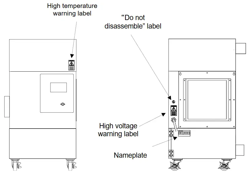
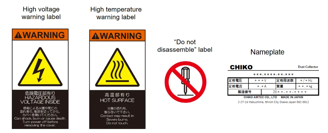
1.6 Safety Label Locations
Chapter 2 Components Identification
2.1 Accessories
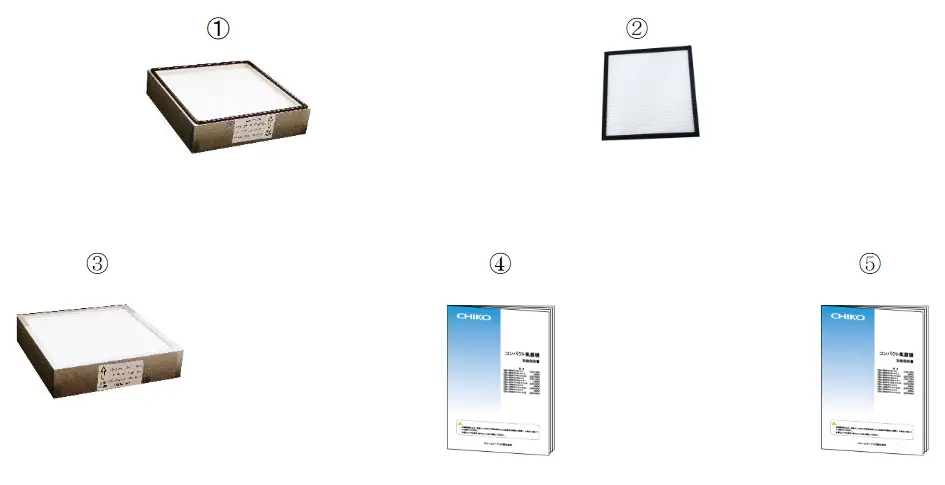
| No | Name | Function | quantity |
| 1 | Primary filter | Captures 99.97% or more of particles 0.3pm or larger. | 1 |
| 2 | Air intake filter for blower cooling | Protects the blower from dust. | 1 |
| 3 | Exhaust filter | Captures 99.97% or more of particles 0.3pm or larger. | 1 |
| 4 | Instruction manual | Provides instructions for using the product. (This document) | 1 |
| 5 | Touch Panel Operating Manual | Provides instructions for using the touch panel of this product. | 1 |
2.2 Device body
2.2.1 CSC-1200TP、 CSC-1500TP、 CSC-2400TP
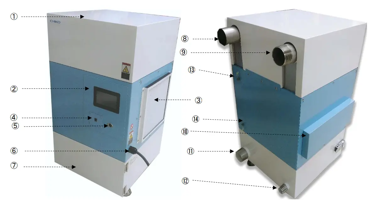
| No | Name | Function |
| 1 | Exhaust box cover | Protective cover. |
| 2 | Touch panel (operation panel) | Used to operate the unit. |
| 3 | Blower cooling air intake filter section | Removes dust from the blower cooling intake air to protect the blower. |
| 4 | Option board connection | Allows connection of an optional board. |
| 5 | Remote connector | Connect a remote cable (sold separately). |
| 6 | Power cable | The cable length is 3m. |
| 7 | Primary filter room | The primary filter is stored in this chamber. |
| 8 | ( pressure) Exhaust side connection | Connects to the air blowpiping. |
| 9 | Exhaust pressure adjustment valve connection port | This is the connection port for the adjustment valve to adjust the exhaust pressure. |
| 10 | Blower cooling exhaust port | Outlet for air that has cooled the Blower. |
| 11 | (-pressure) Air intake side connection port | This is connected to the air intake piping. i |
| 12 | Intake pressure regulating valve connection port | This is the connection port for the adjustment valve that adjusts the inlet pressure. |
| 13 | (+pressure) Nozzle side acquisition port | This is the + pressure acquisition port of the nozzle. |
| 14 | (-pressure) Nozzle side outlet | This is the – pressure acquisition port of the nozzle. |
2.3 Touch panel
Please refer to the separate Touch Panel Operation Manual.
2.4 Preparation before operation
2.4.1 Installation
■ Installation Method
| ・Use two or more people to carry and install the product. There is a risk of injury if the product tumbling. ・After installation is complete, be sure to secure the unit with a stopper. |
■ Installation location
To ensure operating safety and deliver the full performance of the device, install the device in a location that meets the following conditions:
| Item | Description |
| Ambient temperature | 0° to +40°C |
| Ambient humidity | 80 RH% or lower (without dew condensation) |
| Ambient conditions | Indoors (not exposed to direct sunlight), free of corrosive/flammable gases, oil mist, and dust. |
2.4.2 Wiring and Piping
■ Wiring
| • Perform wiring firmly, without bending or pulling cables with excessive force. Fire or electric shock may result. • Ensure that the power supply conforms to the specifications of the device. | ||
| • Be sure to connect the ground wire. | ||
| • Avoid multiple connections as they can cause voltage reduction. At reduced voltage, the device may fail to operate normally, resulting in failure. • As protection against overcurrent, use a ground-fault circuit breaker between the power supply line and the power supply. |
The device is powered by a single-phase supply.
The tolerance of the supply voltage is ±10%.
1. Connect the power supply side of the power cord to the power source.
※This product is not equipped with a shutoff device, so we recommend installing one when connecting it.
Recommended shutoff device [ NV63-SVF 3P 20A ] [ NV63-SVF 3P 30A ] CSC-2400TP only
■Piping
- Connect the piping to the (+ pressure) exhaust side connection port.

- Connect the piping to the (-pressure) air intake side connection.
- Connect the silicone tube to the +pressure nozzle side.
- Connect the silicone tube to the -pressure nozzle side.
※Use a silicone tube with an outer diameter of 4 mm and an inner diameter of 2.7mm.
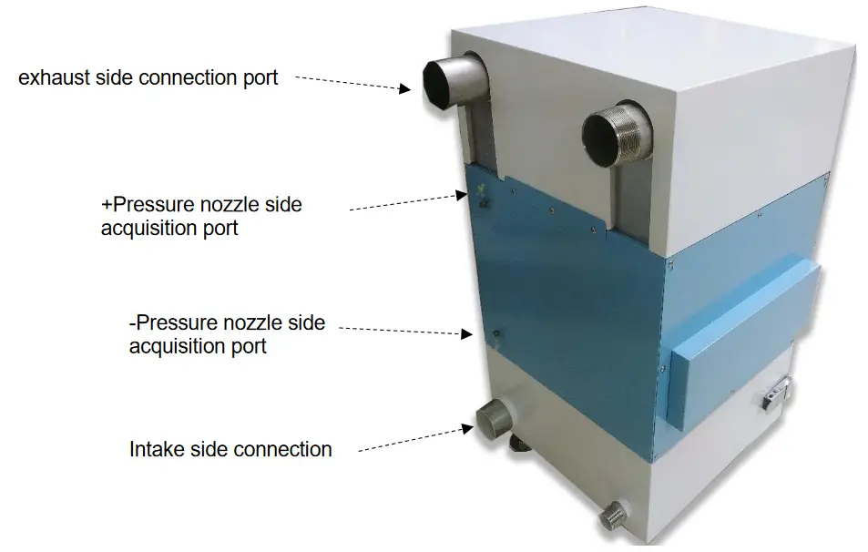
■Connection size
| Model | Exhaust side connection port | Intake side connection | Exhaust side adjustment valve connection port | Intake side adjustment valve connection port |
| CSC-1200TP | 50A socket | 50A socket | 32A | 32A |
| CSC-1500TP | φ63 | φ63 | 50A | 25A |
| CSC-2400TP | Φ75 | Φ75 | 50A | 32A |
2.4.3 Protection function
| If you continue operation with a clogged filter, the following protective functions will be activated. If the protection function is activated, the blower and other parts may be damaged. Immediately inspect the filter and each part. |
■Temperature increase
【CSC-1200TP、CSC-1500TP、CSC-2400TP】
If the motor temperature exceeds 60°C, WARN1 will appear on the display.
Furthermore, if the temperature reaches 70°C, ERR04 will be displayed and the motor will be forced to stop.
2.5 Operation
Please refer to the separate Touch Panel Operation Manual.
Chapter 3 Maintenance and Checkup
| • During maintenance and inspection, be sure to turn off the power and disconnect the power line. • This task requires two or more people. Be sure to wear protective equipment. • If you use a worn or damaged filter, internal electric parts will be damaged. In order to prevent breakdowns and accidents, be sure to perform regular maintenance and inspection. • Replace the filter in an area with sufficient space. • Also, please ensure you install the filter the correct way round. |
| IMPORTANT | • Lay a protective sheet outside the clean room before replacing. • Depending on the type of dust collected, dust may scatter when replacing. Wear protective goggles and mask during any work. |
3.1 Filter maintenance and replacement
| Wipe off any foreign particles adhering to the packing parts with a waste cloth or similar, and clean. Possible cause of trouble such as diminished suction power and dust leakage, etc. |
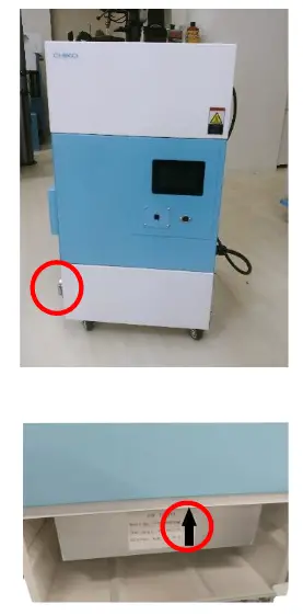
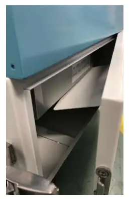
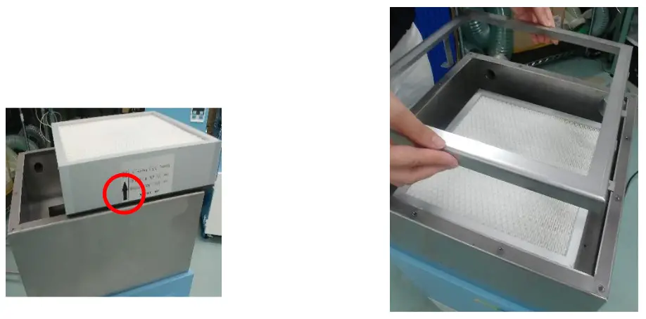
3.1.1 Replacing the primary filter
IMPORTANT Replace the primary filter in an area where there is sufficient space.
- Remove the catch clip.

- Pull the primary filter chamber toward you to replace it.
Set the filter (HEP-3030-69-X) so that the arrow on the seal points upward. - Set the metal plate of the primary filter chamber door so that it is under the filter, and fasten the catch clip.

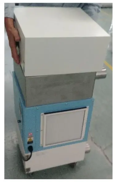
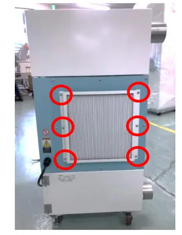
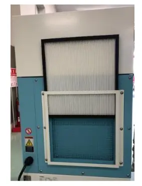
3.1.2 Replacing the exhaust filter
IMPORTANT Replace the exhaust filter in an area where there is sufficient space.
- Pull up and remove the exhaust box cover.

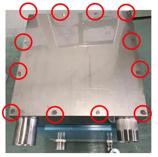
- Remove the tightening screws from the top panel.

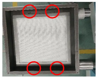
- Remove the tightening screws of the filter frame.
※This does not apply to the CSC1200TP.
4. Replace the exhaust filter.
Set the filter (HEP-3030-69) so that the arrow on the seal points upward.
3.1.3 Replacing the blower cooling intake filter
- Loosen the mounting screws.

- Remove the filter frame and replace it.
3.2 Daily Checkup
| Check item | Frequency | Check that: |
| Filter case | Before operation | Filter case is completely closed. |
| Suction port | Before operation | Suction port is not blocked. |
| Exhaust condition | Once / day | Exhaust port is not blocked. |
| Operation panel condition | Once / day | Error or warning is not displayed. |
3.3 Daily Care Method
| • Be sure to disconnect the plug from the power outlet and confirm that the device is not operating. |
- In case the exterior of the device is dirty, wipe it gently with a soft cloth or a tightly squeezed cloth that will not make any damage on the device easily.
- To remove severe dirt, wet a cloth with neutral detergent diluted with water and wipe it gently.
- Benzine, thinner, gasoline or cleanser must not be used.
3.4 Errors/Warnings
Please refer to the separate Touch Panel Operation Manual.
Troubleshooting
| No. | Trouble phenomenon | Cause | Remedy |
| 1 | Organic EL display shows nothing. | Power not turned on. | Turn on the power. |
| 2 | Motor fails to start or suddenly stops running. | Faulty motor | Call for repair. The motor must be replaced. |
| Stopped due to overload or abnormal temperature | [1]Check that the exhaust/suction ports are not blocked. The ERROR lamp lights up if completely blocked. [2]Check the rated voltage. [3]Avoid multiple (octopus) connections. [4]Avoid motor overheat due to either filter clogging or suction temperature. After checking [1] to [4], take corrective action, and then turn the main power switch off and back on. If the operation cannot resume, the temperature thermostat of the motor may be active. Tum off the main power, and after 30 minutes, resume the operation. | ||
| Primary filter not in place | Install the primary filter correctly. | ||
| Latches are unfastened. | Fastens the latches. | ||
| 3 | Lower suction power | Clogged filter | Replace filters. If filters are left clogged, the device may result in “internal temperature rise or unable to trap particles s. |
| Clogged piping or suction port | Check if piping is clogged or the suction port blocked. | ||
| Faulty motor | Call for repair. The motor must be replaced. | ||
| 4 | Untrapped particles | Improper filter installation | Reinstall filters. |
| Filter broken or past service life | Replace filters. | ||
| Clogged filter | Replace filters. | ||
| 5 | Odd noise or vibration from motor | Foreign matter entered in blower. | Call for repair. |
| Broken motor bearing | Call for repair. |
Note: For other phenomena, contact CHIKO AIRTEC.
Chapter 4 Useful utilization (Optinal)
4.1 Remote Cable
4.1.1 Standard Connection Diagram
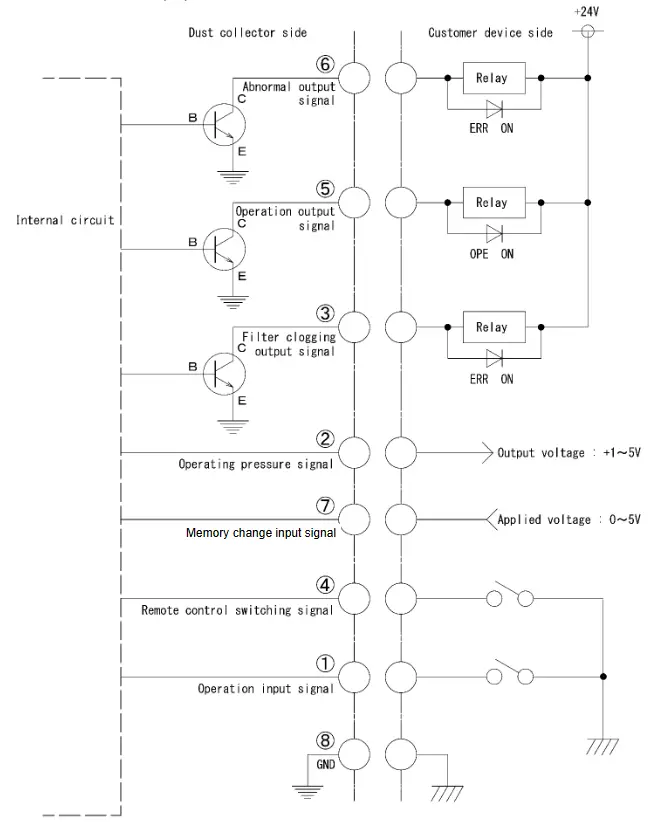
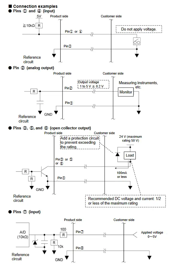
4.1.2 Pin assignment
| Color | Pin No | Signal name | Content | |
| Black | ① | Operation input signal’, | Remote signals (Input) | With ④ and ⑧ short-circuited, ① is shortcircuited to start operation. |
| Red/white | ④ | Remote control switching signal | Short-circuit ④ and ⑧ to shift to remote operation. When short-circuited, operation ON/OFF will not be available on the touch panel. (Lv and PWM can be changed.) | |
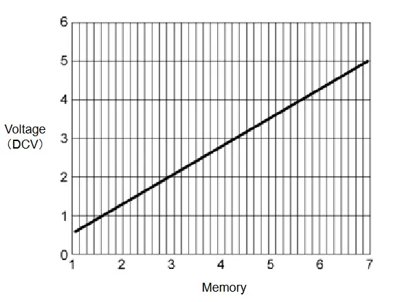
| Yellow | ⑦ | Memory Change input signar | The memory can be changed by applying a voltage of 0 to 5 V between ⑦ and ⑧. | |
| Yellow/white | ⑧ | GND | — | |
| Black/white | ② | Operating pressur e signal | Output signals | Outputs the operating pressure of the differential pressure of the intake side filter. (Analog signal: 1 to 5 V, impedance: ≥ 4.7 k0) |
| Red | ③ | Filter clogging output signal’s | Outputs HI during operation and LO when clogging occurs. | |
| Green | ⑤ | Operation output signal’s | Outputs LO during operation and HI when stopped. | |
| Green/white | ⑥ | Abnormal output signal’s | Outputs HI during operation and LO when an error occurs. | |
【Abnormal output signal】 Pin ⑥ : When any ERR occurred
*1: Contact input (no-voltage contact)
*2: Analog input(0~5V)
Do not apply more than +5.0V.
*3: Open collector output:NPN
The maximum absolute rating is 50 V for voltage and 100 mA for current.
The recommended value is half or less of the rating.
In case of adding an inductor (e.g., relay), install a noise limiter (approx. 33 Ω + 0.1 μF), diode, or the like.
Applied Voltage Threshold Table for Pin ⑦
| Memory | Voltage(DCV) |
| 1 | 0.6~1.1 |
| 2 | 1.2~1.7 |
| 3 | 1.8~2.3 |
| 4 | 2.4~2.9 |
| 5 | 3.0~3.5 |
| 6 | 3.6~4.1 |
| 7 | 4.2~5.0 |
4.1.3 Remote Operation
・To turn operation on/off by remote control, short-circuit pin④and pin⑧.
Short-circuit pin ① → operation ON
Do not short-circuit pin ① → operation OFF See Section 4.1.2 “Pin Assignment”
・Do not short-circuit pins④ and ⑧ when turning operation ON/OFF the signal by the operation of the unit. Follow the instructions in “4.1.2 Pin Assignment” to extract the necessary output signals.
・During the transition to remote operation, operation ON/OFF control cannot be performed on the unit.
4.2 Communication Function
By using optional communication board set (model: RS-485 or RS-EN), you can retrieve information such as operation “ON/OFF” and filter clogging.
4.2.1 RS485 Communication
For details, refer to the instruction manual of the RS485 communication you purchased separately.
4.2.2 Ethernet
For details, refer to the instruction manual of the Ethernet device you purchased separately.
Chapter 5 Appendix
5.1 Specifications
| Model | Motor Rated Output | Voltage | Current value | Frequency | Max. suction volume | Maximum static pressure , | Noise level*1 | Mass |
| CSC-1200TP | 1200W | 200~230V Single-phase | 15A | 50/60 Hz | 3.0 m³/min | 12.4kPa | 69~72dBA | 32kg |
| CSC-1500TP | 1200W | 200~230V Single-phase | 15A | 50/60 Hz | 3.9m³/min | 22.0kPa | 71~73.5dBA | 46kg |
| CSC-2400TP | 1200W x2 | 200~230V Single-phase | 30A | 50/60 Hz | 7.4 m³/min | 20.0kPa | 72~75dBA | 61kg |
*1: Maximum statie pressure is intake side – pressure value
*2: Noise value is measured with a hose connected to the suction port, at a distance of 1 m from the device, on the A scale ㏈.
5.2 Consumables List
| Filter | Primary filter | Air intake filter for blower cooling | Exhaust filter |
| Replacement time | 6 months | 6 to 12 months | 6 to 12 months |
| CSC-1200TP | HEP-2525-50-X | CHF-2525-13 | HEP-2525-50 |
| CSC-1500TP | HEP-3030-69-X | HEP-3030-69 | |
| CSC-2400TP |
*: The replacement intervals vary with the use frequency, environment, and suction concentration (substance and composition) at the customer’s site.
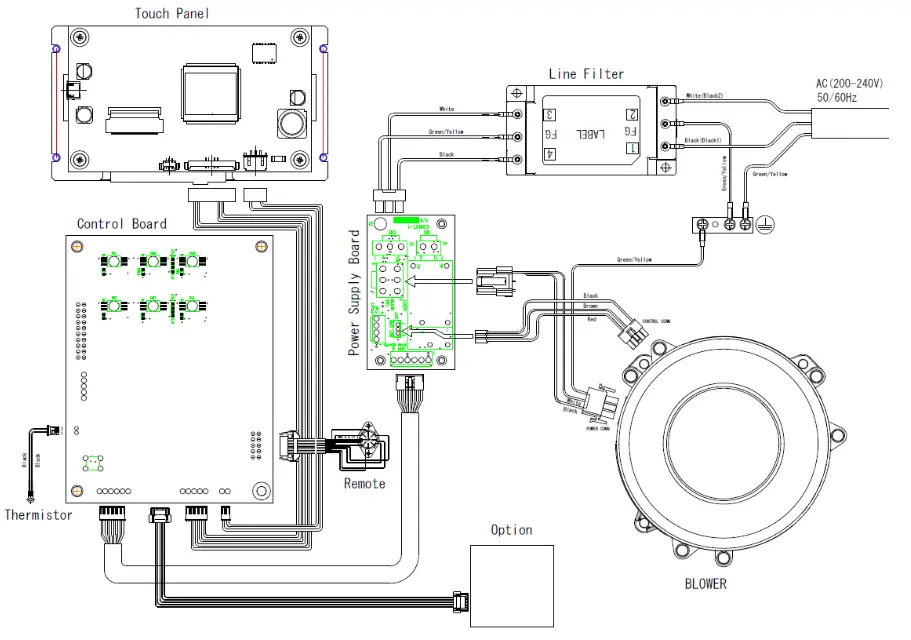
5.3 Electrical Diagram
5.3.1 CSC-1200TP、 CSC-1500TP
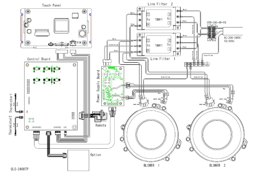
5.3.2 CSC-2400TP
■ Scope of Warranty and Responsibility
● Warranty period
We will repair free of charge any failures or damages that may occur during normal operating conditions within 12 months of shipment.
However, this does not apply to the consumables listed in “5.2 Consumables List”.![]() “5.2 Consumables List” (page 38)
“5.2 Consumables List” (page 38)
The following cases will be handled as a charged service even within the warranty period.
- Failure or damage caused by violation of the instructions in this document.
- Failure or damage due to use in an operating environment other than that described in this document.
- Repair, alteration, disassembly, or similar action done any party other than CHIKO AIRTEC or a CHIKO AIRTEC-designated sales agent.
- Blemish, contamination, or other appearance change that may occur during use.
- Replacement of any consumable or accessory, or use of any part not designated by CHIKO AIRTEC.
- Failure of damage due to falling after purchase or accident during transport.
- Failure or damage due to natural disasters, such as: fire, salt damage, gaseous damage, earthquake, wind and flood damage, lightning strike, and abnormal voltage.
● Repairs
Travel expenses for on-site service will be chargeable whether within or outside the warranty period.
For repair reasons, improved parts may be used for repair.
CHIKO AIRTEC will not be liable for any damage resulting from use of this device, such as damage caused by failure of the device or by erasion of data.
■ Memo about purchase
| Model | Serial No. | |
| Date of purchase | Operation start date: | |
| Your name | ||
| Address | Phone Person in charge | |
CHIKO AIRTEC CO.,LTD.
2-27-24,Hakushima, Minoh, Osaka 562-0012, Japan
TEL (81) 072-720-5151 FAX (81) 072-720-5133
URL http://chiko-airtec.jp/


