![]()
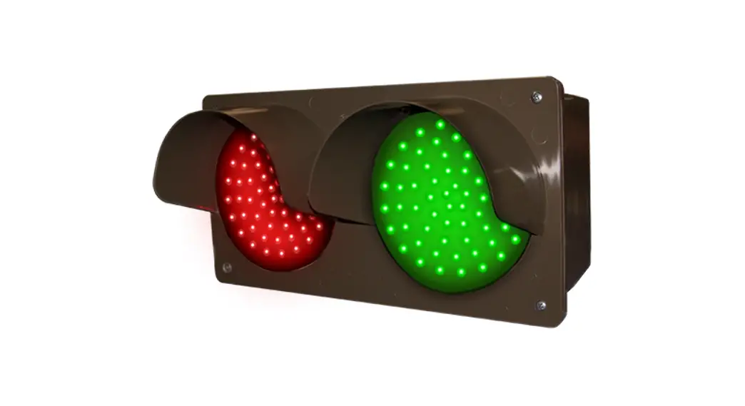
TCIL LED SERIES ![]()
Installation Instructions
Voltage
This sign operates within an input range of 120VAC to 277VAC.
Installation Steps
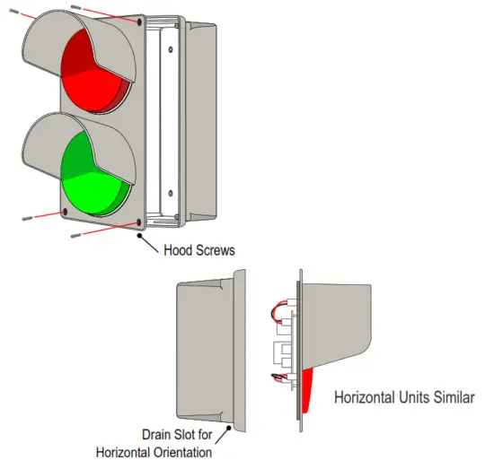
- Remove the hood from the housing by unscrewing the four retaining screws on the front of the unit.
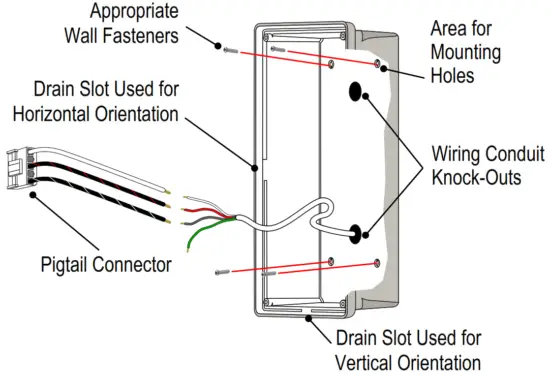
- Use a 5/16″ drill bit to drill (4) four holethe housing for mounting fasteners and 7⁄8″ drill bit for conduit.

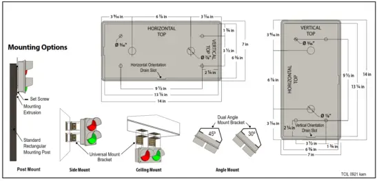
- For Surface Mounting
The housing MUST be oriented correctly, molded intothe back of the housing locate the HORIZONTAL TOP or the VERTICAL TOP and orient accordingly. There are drain slots molded into the bottom of each orientation. Mount the housing securely to the surface using four appropriate fasteners (not supplied).
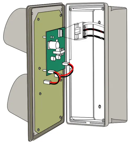
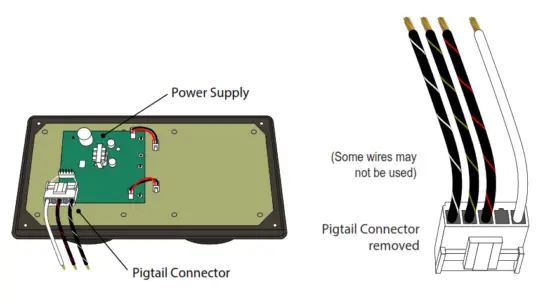
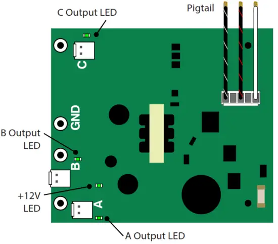
- Disconnect the wiring pigtail from the circuit board to make wiring connections, see diagram on back
- Plug pigtail into the circuit board and replace the hood and the four retaining screws removed in step 1.

Note: Do not overtighten fasteners or distort back panel.![]() Note: This sign is intended to be installed in ccordance with the requirements of Article 600 of the National Electric Code and/or other applicable local codes. This includes proper grounding and bonding of the sign.
Note: This sign is intended to be installed in ccordance with the requirements of Article 600 of the National Electric Code and/or other applicable local codes. This includes proper grounding and bonding of the sign.
Wall Mounting Dimensions
Making your Wiring Connections
- To make your electrical connections easier, gently unplug the supplied wired pigtail connector from the power supply.

- With your incoming power already running through the mounted back you can easily make all connections to the pigtail using wire connectors. (See table below for general wiring guidelines)
- Plug the pigtail connector back into the power supply to fnish of the electrical part of your installation. The connector is “keyed” and can only be installed in one orientation
- You’re done with the electrical! Time to close up the sign by pushing the cabinet closed and replacing the two screws you removed from the bottom of the cabinet.
![]() Note: Make appropriate wiring connections per local code.
Note: Make appropriate wiring connections per local code.
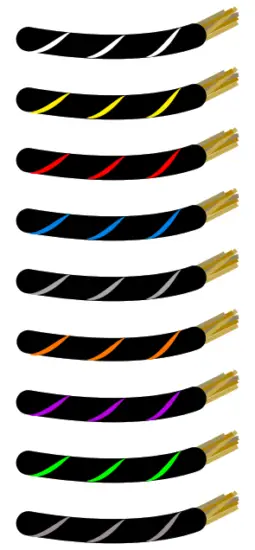
General Wiring Guidelines*
*Neutral is solid White and Ground (if equipped) is solid Green.
| Number ofMessages | Typical Wire (Lead) Colors | ||
| Message 1 | Black with White Stripes | ||
| Message 2 | Black with Yellow Stripes | ||
| Message 3 | Black with Red Stripes | ||
| Message 4 | Black with Blue Stripes | ||
| Message 5 | Black with Gray Stripes | ||
| Message 6 | Black with Orange Stripes | ||
| Message 7 | Black with Purple Stripes | ||
| Message 8 | Black with Green Stripes | ||
| Message 9 | Black with Brown Stripes | ||
 Wiring Label Sample for a typical 2 Message OPEN | CLOSED Sign
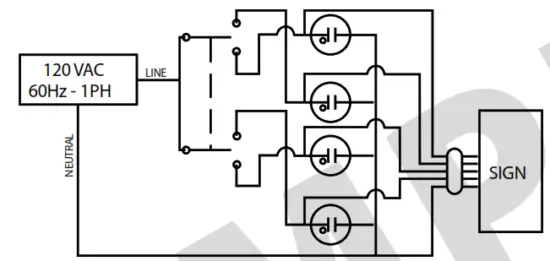
Sign connections are rated for 120-277 VAC Wire colors not listed here are unused.
NOTES:
- SWITCH TYPE MAY VARY THIS IS ONLY A TYPICAL
- SIGN LEAD COLOR CHART IS SHOWN BELOW
- INDICATOR LIGHTS ARE OPTIONAL AND WIRED IN PARALLEL TO SIGN MESSAGE
Product ID: 5887
| Message | Wire Color |
| Open | Black with White Stripes |
| Closed | Black with Yellow Stripes |
| NEUTRAL | White |
| GROUND (IF EQUIPPED) | Green |
![]() Note: Refer to the wiring label inside the sign for the specific instructions on wiring your sign. Some wires may not be used.
Note: Refer to the wiring label inside the sign for the specific instructions on wiring your sign. Some wires may not be used.
![]() Note: Make appropriate wiring connections per local code.
Note: Make appropriate wiring connections per local code.
Note: Any holes drilled into sign cabinet ST be sealed. Failure to do so may cause a short and void warranty.
Note: This sign is intended to be installed in accordance with the requirements of Article 600 of the National Electric Code and/or other applicable local codes. This ncludes proper grounding and bonding of the sign.
Note: This unit contains a built-in CLASS 2 LED driver.
WARNING – Risk of Fire or Electric Shock. Do Not interconnect output terminations.
Normal Operation
There is one (1) LED on the power supply located close to the connector with the Red and Black wires. This LED marked V OUT, will illuminate green hen 120 – 277VAC power is applied to the Pigtail.
Check the LED on each power supply since there may be more than one power supply per message.
![]() Note: Transformer on power supply converts 120 – 277VAC to 12V.
Note: Transformer on power supply converts 120 – 277VAC to 12V.
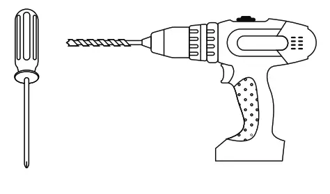
What You Need:
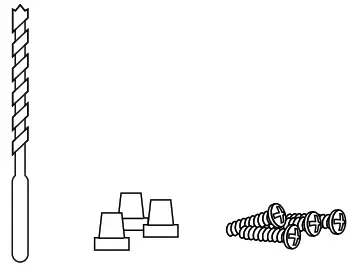
Phillips Head Screw Driver Drill with a 5/16″ and 7/8″ drill bit(not supplied)
(4) Appropriate Wall Fasteners (not supplied)
Wire Connectors (not supplied)
Control Switch (ordered separately)
![]() Always turn of the power prior to installation.
Always turn of the power prior to installation.
![]() Be sure any metal debris clearedout of the cabinet.
Be sure any metal debris clearedout of the cabinet.


