CLOCKAUDIO TS 005 Touch Switches
The TS 005 capacitive touch switch is specially designed for use with Clockaudio’s through table microphones. With no moving parts, low-profile mounting and encapsulated electronics, TS 005 provide multiple colors, clear and precise visual operational status as well as protection from office contaminants affecting its operation. Comes with a modular under desk mount TS-C1 controller for easy installation.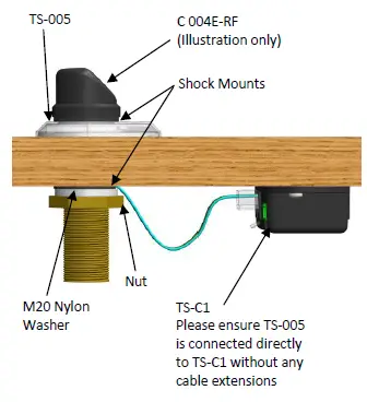
- Self-calibrating, low profile mount capacitive touch switch facilitating click/pop-free switching of a microphone from DSP.
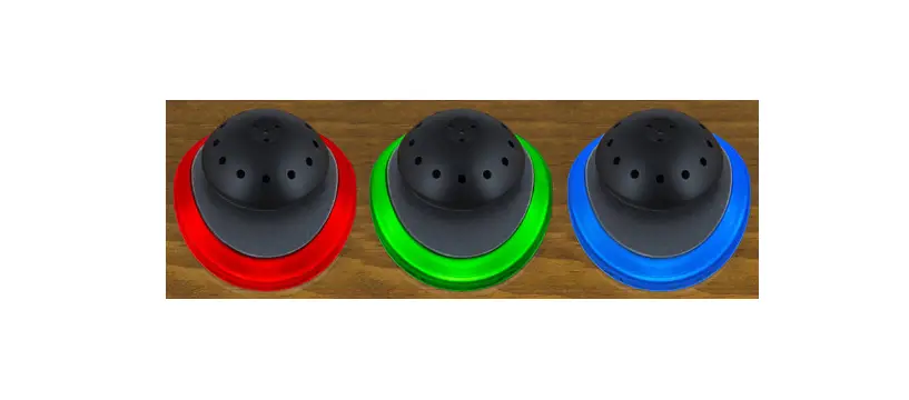
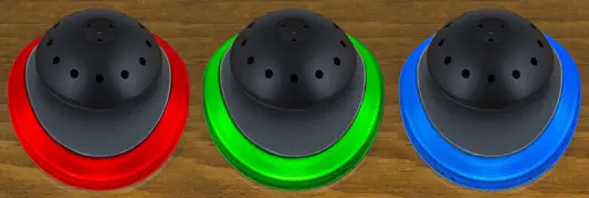
- RGB LED provides a multi-color combination for clear precise visual status of the microphone.
- Suitable for fitting Clockaudio’s C 003E-RF, C 004E-RF, C 011E-RF, C 012E-RF microphones, SM 10, and SM 20-RF stands.
- No moving parts and employing surface mount technology ensures extreme reliability, longevity, and trouble-free use.
- Electronic circuitry fully encapsulated to protect the operation from spills or other contaminants.
- Terminated with RJ 45 connector and supplied with a touch switch controller (TS-C1) allows connection via CAT 5E patch cable back to CDT-100, CUI-2 or directly to DSP.
- Programmable via DSP to operate in PTT, PTM or latching modes.
- 12V DC operation using a regulated power supply, CDT-100 or CUI-2
- Fitted with 200mm cable that connects to SWITCH on TS-C1
- RS-IN on TS-C1 provides connectivity to an external switch.
- Backward compatible with CH32, providing Red/Green output.
- The maximum current consumption for TS 005 with TS-C1 is 140mA.
- Finished in clear polycarbonate.
- Order codes: TS 005 (black) and TS 005W (white)
Installation guide
- Using supplied template, drill a 24mm (61/64”) hole through the table and a 3.2mm (1/8”) hole at least 6mm (1/4”) deep into the table.
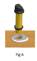
- Place TS 005 into position. Remove nut, M20 nylon washer and lower shock mount, push-fit the microphone through the TS 005 ensuring the microphone front is aligned to the TS 005’stouchpad. See Fig A.

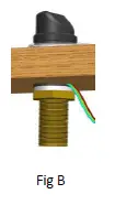
- Fit the shock mount and M20 nylon washer onto the microphone barrel and, ensuring ribbon cable is not twisted, hand tighten the nut. See Fig B.

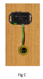
- Connect ribbon cable from TS 005 to SWITCH on TS-C1 and mount the TS-C1 nearby. See Fig C
 Note: microphone screen and TS-C1 ground must have a common ground connection.
Pin number Function 1 Switch (Low indicating contacts closed on RS-IN) 2 Red LED (pulled low to illuminate) 3 Ground 4 +12V DC 5 Touch Switch Activated 6 Green LED (pulled low to illuminate) 7 Blue LED (pulled low to illuminate) 8 No connection - TS-C1’s CONTROL port wiring for connection to control system.
- Ensure all connections are made prior to applying power.
 Note: microphone screen and TS-C1 ground must have a common ground connection.
Clockaudio. All rights reserved. Product specifications are subject to change without notification


 Mcoetps412 Manual")

 - Uk Mcoetps312 Manual")
