
MCOETPS412 MCO Home Glass Touch Switch GEN5 2 Buttons User Manual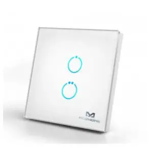
Quick start
This is a Binary Power Switch for XXXQFrequencyName. To run this device please connect it to your mains power supply. A This device is a Z-Wave
Actuator. To include or exclude the device you only need to press and hold any key for 8 seconds.
Important safety information
Please read this manual carefully. Failure to follow the recommendations in this manual may be dangerous or may violate the law. The manufacturer, importer, distributor and seller shall not be liable for any loss or damage resulting from failure to comply with the instructions in this manual or any other material. Use this equipment only for its intended purpose. Follow the disposal instructions. Do not dispose of electronic equipment or batteries in a fire or near open heat
sources.
Product Description
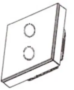
The TPS412 by MCO Home is a wall switch with 2 integrated switch relays. The relays can be controlled both with the touch switches, which are integrated into the glass surface, and via Z-Wave commands. The relays can switch two loads with up to 1,100 watts each. Beside local switching the device can be used to control two groups of directly associated devices. A blue LED on every button indicates the switching status.
The wall switch can be easily connected to an electrical load without installing a flush mounted module separately. The relays are located inside a module which is directly connected to the glass touch button. With that MCO Home wall switch you can replace any switch insert or toggle switch. The wall switch can be mounted on any flush box.
With the stylish glass wall switches by MCO Home you can easily integrate your already installed lights into your home automation network. Without installing any news cable, you can switch your lighting as usual via wall switch – but thanks to Z-Wave technology also via remote control, smartphone or sensor controlled automation.
Installation
Important: Please make sure you have cut off power supply before you start to install the device.
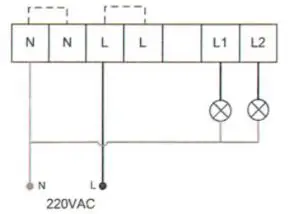
- Connect Hot Line to “L”
- Connect Neutral Line to “N”
- Connect Load wire to “L1”
- Connect Load wire to “L2”
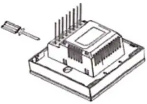
- Remove the steel frame from the device, and secure it onto the junctions box with tow screws.

- Insert all wires into the right terminals and tighten screws.

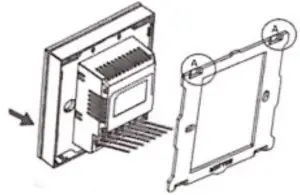
- Attach the wired device on “A” points of the steel frame as shown first, and then push the whole device into junction box.

- Confirm the device is well mounted, power on and it is ready to operate.


Product Usage
The actuator is operated by the local switching Touch pannels or wirelessly using Z-Wave commands.
Scene Function:
- Scene Response Device
As a Scene Response device, it supports “Scene Activation CC” and “Scene Actuator Conf CC” ,which make the device can be added into any scene , and supports 255 Scene ID. In parameter item 0x10, users can configure which external switch button will respond the scene CC. - Scene Activate Device
As a Scene Activate device, when pressing the switch button, it will send “Scene Activation” to Association Group 1 (normally associated to the gateway) to activate corresponding scenes, and the scene ID is set by configuration parameter. This function is disabled by default, to activate it, please refer to the configuration parameter table item 17-19. - Central Scene Activate Device
As a Central Scene Activate device, it supports “Central Scene CC”. When pressing the switch button, it will send “Central Scene Notification” to Association Group 1 (normally associated to gateway). This function is always being activated and cannot be disabled.
| Reset to factory default | XXX Reset Description |
| Inclusion | To include the device you only need to press and hold any key for 8 seconds. |
| Exclusion | To exclude the device you only need to press and hold any key for 8 seconds. |
| NIF | XXXNIF |
| Wakeup | XXX Wakeup Description |
| Protection | XXX Protection |
| Firmware Update | XXX Firm ware Update |
| Set Association | XXX Set Association |
Association Groups:
| Group Number Maximum Nodes Description | ||
| 1 | 1 | Lifeline |
| 2 | 5 | Associate with Key 1 – send Basic Set Command to associated devices |
| 5 | 5 | Associate with Key 2 – send Basic Set Command to associated devices |
Configuration Parameters
Parameter 2: Switch state saved or not when power failure
Size: 1 Byte, Default Value: 1
| Setting Description | |
| 0 | not saved҅ switch will be off when powered again |
| 1 | saved҅s witch will keep the same state when powered again |
Parameter 3: ALL ON/ALL OFF
Size: 1 Byte, Default Value: 255
| Setting | Description |
| 0 | forbid ALL ON, forbid ALL OFF |
| 1 | forbid ALL ON, allow ALL OFF |
| 2 | allow ALL ON, forbid ALL OFF |
| 255 | allow ALL ON, allow ALL OFF |
Parameter 4: LED Backlit brightness level
Size: 1 Byte, Default Value: 10
| Setting Description | |
| 0 | LED disabled |
| 1 – 10 | Min level-Max level |
Parameter 5: Key Mode
This function works for corridor or stairwell situation.
Size: 1 Byte, Default Value: 0
| Setting Description | |
| 0 | single click to switch on/off status |
| 1 | Key default as off state. When it is turned on, then it will be turned off automatically after a time period can be set in item 6 |
| 2 | Key default as on state. When it is turned off, then it will be turned on automatically after a time period can be set in item 6 |
| 3 | hold >3s then key is on, and off once released |
| 4 | single click to switch on/off status + hold >3s then key is on, and off once released |
Parameter 6: Key On duration
Size: 2 Byte, Default Value: 0
| Setting Description | |
| 0 | infinite |
| 1 – 65535 | unit sec |
Parameter 8: Basic CC integration setting
This parameter works for integration with different gateways/systems. If do not know how to use, pls keep as default.
Size: 1 Byte, Default Value: 0
| Setting Description | |
| 0 | Basic Set received҅key 1 responds; Basic Get received҅key 1 sends Basic Report; key 1 will not se unsolicited Basic ReportҁNo Endpoint҂to LifeLine Association |
| 1 | Basic Set received҅key 1 responds; Basic Get received҅key 1 sends Basic Report; key 1 will send unsolicited Basic ReportҁNo Endpoint҂to LifeLine Association |
| 2 | Basic Set received҅all keys respond; Basic Get received҅not reply Basic Report; All keys will not se unsolicited Basic ReportҁNo Endpoint҂ to LifeLine Association |
| 3 | Basic Set received҅all keys respond; Basic Get received҅key 1 sends Basic Report; All keys will not unsolicited Basic ReportҁNo Endpoint҂to LifeLine Association |
Parameter 16: Scene respond
Size: 1 Byte, Default Value: 0
| Setting Description | |
| 0 | Scene respond disabled |
| 1 | Key1 respond scene |
Parameter 17: Key1 Scene Activate Mode Setting
Size: 1 Byte, Default Value: 0
| Setting Description | |
| 0 | Scene activate function disabled |
| 1 | One click key1 always activate scene ID1 no matter what the status of key1 is. |
| 2 | One click key1,only activate scene ID1 when key1‘s relay output is open |
| 3 | One click key1,only activate scene ID1 when key1‘s relay output is close |
Parameter 18: Key1 Activate Scene ID
Size: 1 Byte, Default Value: 00
| Setting Description | |
| 0 | Scene ID is invalid and will not send scene activate command. |
| 1 – 255 | Scene ID |
Parameter 19: Key1 Activate Scene Duration
Size: 1 Byte, Default Value: 0
| Setting Description | |
| 0 | Instantly |
| 1 – 127 | Dimming durations from 1 second to 127 seconds in 1-second resolution |
| 128 – 254 | Specify dimming durations from 1 minute to 127 minutes in 1-minute resolution. |
Parameter 20: Key 2 Scene Activate Mode Setting
Size: 1 Byte, Default Value: 0
| Setting Description | |
| 0 | Scene activate function disabled |
| 1 | One click key2 always activate scene ID1 no matter what the status of key2 is. |
| 2 | One click key2,only activate scene ID1 when key2‘s relay output is open |
| 3 | One click key2,only activate scene ID1 when key2‘s relay output is close |
Parameter 21: Key2 Activate Scene ID
Size: 1 Byte, Default Value: 00
| Setting Description | |
| 0 | Scene ID is invalid and will not send scene activate command. |
| 1 – 255 | Scene ID |
Parameter 22: Key2 Activate Scene Duration
Size: 1 Byte, Default Value: 0
| Setting Description | |
| 0 | Instantly |
| 1 – 127 | Dimming durations from 1 second to 127 seconds in 1-second resolution |
| 128 – 254 | Specify dimming durations from 1 minute to 127 minutes in 1-minute resolution. |
Parameter 255: Factory Reset
Size: 1 Byte, Default Value: 0
| Setting Description | |
| 85 | Factory Reset |
Technical Data
| Dimensions | 86 x 86 x 39 mm |
| Weight | 180 gr |
| Hardware Platform | ZM5101 |
| EAN | 4251295700755 |
| IP Class | IP 20 |
| Voltage | 230V |
| Load | 5A |
| Device Type | On/Off Power Switch |
| Generic Device Class | Binary Switch |
| Specific Device Class | Binary Power Switch |
| Firmware Version | 05.02 |
| Z-Wave Version | 04.3e |
| Z-Wave Product Id | 0x015f.0x4121.0x5102 |
| Frequency | Europe – 868,4 Mhz |
| Maximum transmission power | 5 mW |

 Mcoetps412 Manual")
 Mcoetps411 Manual")
 - Uk Mcoetps312 Manual")
 - Uk Mcoetps314 Manual")
, British Standard Mcoetps314_700 Manual")


