
MCO Home
SKU: MCOETPS411

Quickstart
This is a
On/Off Power Switch
for
Europe.
To run this device please connect it to your mains power supply.
A” This device is a Z-Wave Actuator. To include or exclude the device you only need to press and hold any key for 8 seconds.
Important safety information
Please read this manual carefully. Failure to follow the recommendations in this manual may be dangerous or may violate the law.
The manufacturer, importer, distributor and seller shall not be liable for any loss or damage resulting from failure to comply with the instructions in this manual or any other material.
Use this equipment only for its intended purpose. Follow the disposal instructions.
Do not dispose of electronic equipment or batteries in a fire or near open heat sources.
What is Z-Wave?
Z-Wave is the international wireless protocol for communication in the Smart Home. This
device is suited for use in the region mentioned in the Quickstart section.

Z-Wave ensures a reliable communication by reconfirming every message (two-way
communication) and every mains powered node can act as a repeater for other nodes
(meshed network) in case the receiver is not in direct wireless range of the
transmitter.
This device and every other certified Z-Wave device can be used together with any other
certified Z-Wave device regardless of brand and origin as long as both are suited for the
same frequency range.
If a device supports secure communication it will communicate with other devices
secure as long as this device provides the same or a higher level of security.
Otherwise it will automatically turn into a lower level of security to maintain
backward compatibility.
For more information about Z-Wave technology, devices, white papers etc. please refer
to www.z-wave.info.
Product Description
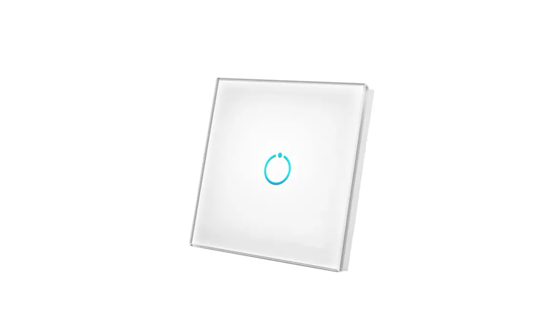
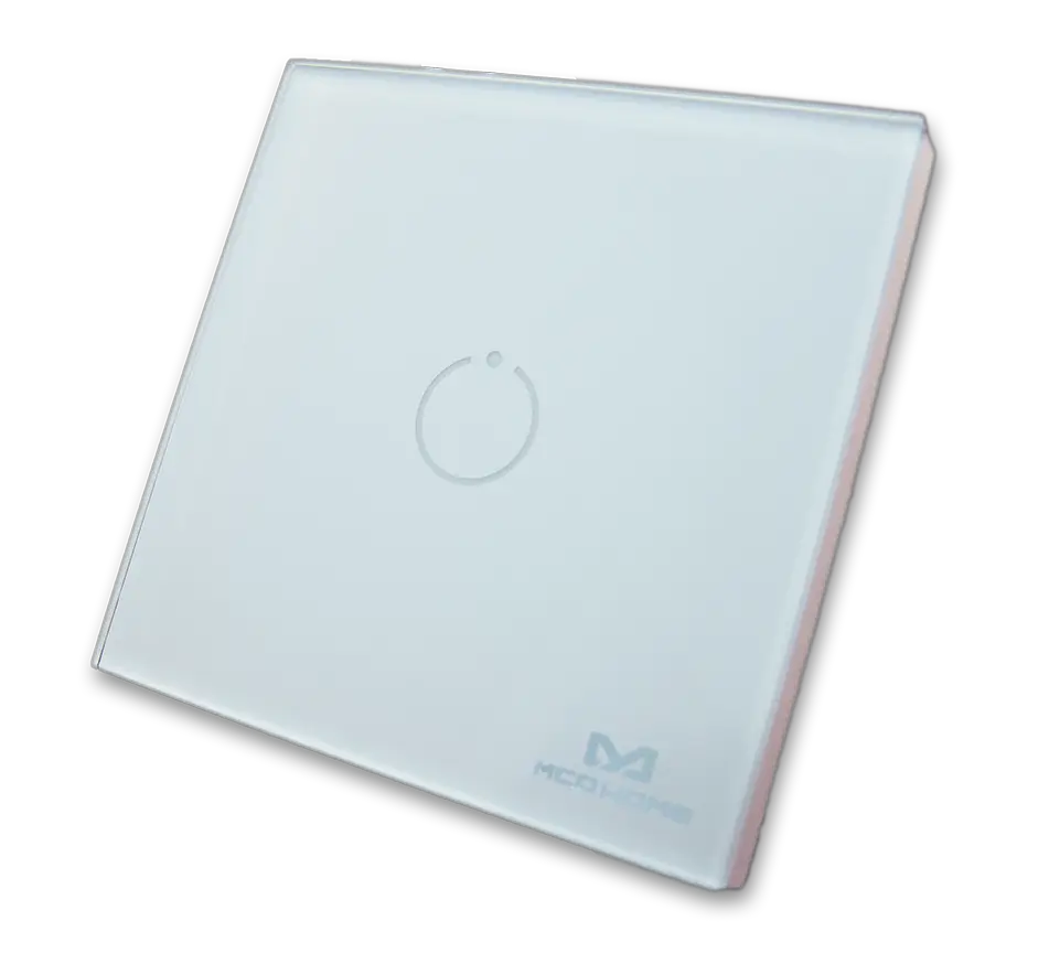
The TPS411 by MCO Home is a wall switch with integrated switch relay. The relay can be controlled both with the touch switch, which is integrated into the glass surface, and via Z-Wave commands. The relay can switch a load with up to 1,100 watts. ” Beside local switching the device can be used to control two groups of directly associated devices. A blue LED on every button indicates the switching status.
The wall switch can be easily connected to an electrical load without installing a flush mounted module separately. The relay is located inside a module which is directly connected to the glass touch button. With that MCO Home wall switch you can replace any switch insert or toggle switch. The wall switch can be mounted on any flush box.
With the stylish glass wall switches by MCO Home you can easily integrate your already installed lights into your home automation network. Without installing any news cable, you can switch your lighting as usual via wall switch – but thanks to Z-Wave technology also via remote control, smartphone or sensor-controlled automation.”
Prepare for Installation / Reset
Please read the user manual before installing the product.
In order to include (add) a Z-Wave device to a network it must be in factory default
state. Please make sure to reset the device into factory default. You can do this by
performing an Exclusion operation as described below in the manual. Every Z-Wave
controller is able to perform this operation however it is recommended to use the primary
controller of the previous network to make sure the very device is excluded properly
from this network.
Safety Warning for Mains Powered Devices
ATTENTION: only authorized technicians under consideration of the country-specific
installation guidelines/norms may do works with mains power. Prior to the assembly of
the product, the voltage network has to be switched off and ensured against re-switching.
Installation
Important: Please make sure you have cut off power supply before you start to install the device.
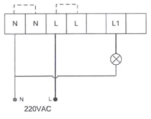
- Connect Hot Line to “L”
- Connect Neutral Line to “N”
- Connect Load wire to “L1”
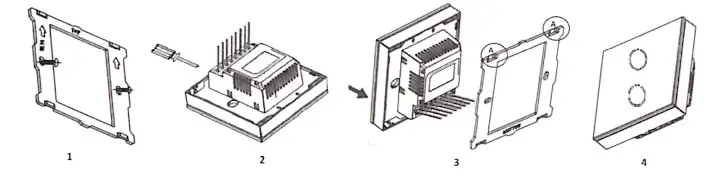
- Remove the steel frame from the device, and secure it onto the junctions box with tow screws.
- Insert all wires into the right terminals and tighten screws.
- Attach the wired device on “A” points of the steel frame as shown first, and then push the whole device into junction box.
- Confirm the device is well mounted, power on and it is ready to operate.
Inclusion/Exclusion
On factory default the device does not belong to any Z-Wave network. The device needs
to be added to an existing wireless network to communicate with the devices of this network.
This process is called Inclusion.
Devices can also be removed from a network. This process is called Exclusion.
Both processes are initiated by the primary controller of the Z-Wave network. This
controller is turned into exclusion respective inclusion mode. Inclusion and Exclusion is
then performed doing a special manual action right on the device.
Inclusion
To include the device you only need to press and hold any key for 8 seconds.
Exclusion
To exclude the device you only need to press and hold any key for 8 seconds.
Product Usage
The actuator is operated by the local switching Touch pannels or wirelessly using Z-Wave commands.
Scene Function:
item 0x10, users can configure which external switch button will respond the scene CC.
refer to the configuration parameter table item 17-19.
Quick trouble shooting
Here are a few hints for network installation if things dont work as expected.
- Make sure a device is in factory reset state before including. In doubt exclude before include.
- If inclusion still fails, check if both devices use the same frequency.
- Remove all dead devices from associations. Otherwise you will see severe delays.
- Never use sleeping battery devices without a central controller.
- Dont poll FLIRS devices.
- Make sure to have enough mains powered device to benefit from the meshing
Association – one device controls an other device
Z-Wave devices control other Z-Wave devices. The relationship between one device
controlling another device is called association. In order to control a different
device, the controlling device needs to maintain a list of devices that will receive
controlling commands. These lists are called association groups and they are always
related to certain events (e.g. button pressed, sensor triggers, …). In case
the event happens all devices stored in the respective association group will
receive the same wireless command wireless command, typically a ‘Basic Set’ Command.
Association Groups:
Group NumberMaximum NodesDescription
| 1 | 1 | Lifeline |
| 2 | 5 | Associate with Key 1 -” send Basic Set Command to associated devices |
Configuration Parameters
Z-Wave products are supposed to work out of the box after inclusion, however
certain configuration can adapt the function better to user needs or unlock further
enhanced features.
IMPORTANT: Controllers may only allow configuring
signed values. In order to set values in the range 128 … 255 the value sent in
the application shall be the desired value minus 256. For example: To set a
parameter to 200 it may be needed to set a value of 200 minus 256 = minus 56.
In case of a two byte value the same logic applies: Values greater than 32768 may
needed to be given as negative values too.
Parameter 2: Switch state saved or not when power failure
Size: 1 Byte, Default Value: 1
SettingDescription
| 0 | not saved,switch will be off when powered again |
| 1 | saved,switch will keep the same state when powered again |
Parameter 3: ALL ON/ALL OFF
Size: 1 Byte, Default Value: 255
SettingDescription
| 0 | forbid ALL ON, forbid ALL OFF |
| 1 | forbid ALL ON, allow ALL OFF |
| 2 | allow ALL ON, forbid ALL OFF |
| 255 | allow ALL ON, allow ALL OFF |
Parameter 4: LED Backlit brightness level
Size: 1 Byte, Default Value: 10
SettingDescription
| 0 | LED disabled |
| 1 – 10 | Min level-Max level |
Parameter 5: Key Mode
This function” works for” corridor or” stairwell” situation.
Size: 1 Byte, Default Value: 0
SettingDescription
| 0 | single click to switch on/off status |
| 1 | Key default as off state. When it is turned on, then it will be turned off automatically after a time period , which can be set in item 6 |
| 2 | Key default as on state. When it is turned off, then it will be turned on automatically after a time period , which can be set in item 6 |
| 3 | hold >3s then key is on, and off once released |
| 4 | single click to switch on/off status + hold >3s then key is on, and off once released |
Parameter 6: Key On duration
Size: 2 Byte, Default Value: 0
SettingDescription
| 0 | infinite |
| 1 – 65535 | unit sec |
Parameter 8: Basic CC integration setting
This parameter” works for” integration with” different” gateways/systems. If do not” know how to” use, pls keep as” default.
Size: 1 Byte, Default Value: 0
SettingDescription
| 0 | Basic Set received,key 1 responds; Basic Get received,key 1 sends Basic Report; key 1 will not send unsolicited Basic Report(No Endpoint)to LifeLine Association |
| 1 | Basic Set received,key 1 responds; Basic Get received,key 1 sends Basic Report; key 1 will send unsolicited Basic Report(No Endpoint)to LifeLine Association |
| 2 | Basic Set received,all keys respond; Basic Get received,not reply Basic Report; All keys will not send unsolicited Basic Report(No Endpoint) to LifeLine Association |
| 3 | Basic Set received,all keys respond; Basic Get received,key 1 sends Basic Report; All keys will not send unsolicited Basic Report(No Endpoint)to LifeLine Association |
Parameter 16: Scene respond
Size: 1 Byte, Default Value: 0
SettingDescription
| 0 | Scene respond disabled |
| 1 | Key1 respond scene |
Parameter 17: Key1 Scene Activate Mode Setting
Size: 1 Byte, Default Value: 0
SettingDescription
| 0 | Scene activate function disabled |
| 1 | One click key1 always activate scene ID1 no matter what the status of key1 is. |
| 2 | One click key1,only activate scene ID1 when key1‘s relay output is open |
| 3 | One click key1,only activate scene ID1 when key1‘s relay output is close |
Parameter 18: Key1 Activate Scene ID
Size: 1 Byte, Default Value: 00
SettingDescription
| 0 | Scene ID is invalid and will not send scene activate command. |
| 1 – 255 | Scene ID |
Parameter 19: Key1 Activate Scene Duration
Size: 1 Byte, Default Value: 0
SettingDescription
| 0 | Instantly |
| 1 – 127 | Dimming durations from 1 second to 127 seconds in 1-second resolution |
| 128 – 254 | Specify dimming durations from 1 minute to 127 minutes in 1-minute resolution. |
Parameter 255: Factory Reset
Size: 1 Byte, Default Value: 0
SettingDescription
| 85 | Factory Reset |
Technical Data
| Dimensions | 86 x 86 x 39 mm |
| Weight | 180 gr |
| Hardware Platform | ZM5101 |
| EAN | 4251295700762 |
| IP Class | IP 20 |
| Voltage | 230 images/manufacturers/MCO_Home.png |
| Load | 5A |
| Device Type | On/Off Power Switch |
| Generic Device Class | Binary Switch |
| Specific Device Class | Binary Power Switch |
| Firmware Version | 05.02 |
| Z-Wave Version | 04.3e |
| Z-Wave Product Id | 0x015f.0x4111.0x5102 |
| Frequency | Europe – 868,4 Mhz |
| Maximum transmission power | 5 mW |
Supported Command Classes
- Basic
- Switch Binary
- Switch All
- Scene Activation
- Scene Actuator Conf
- Association Grp Info
- Device Reset Locally
- Central Scene
- Zwaveplus Info
- Multi Channel
- Configuration
- Manufacturer Specific
- Powerlevel
- Firmware Update Md
- Association
- Version
- Multi Channel Association
- Switch Multilevel
- Transport Service
Controlled Command Classes
- Basic
- Central Scene
- Switch Multilevel
- Transport Service
Explanation of Z-Wave specific terms
- Controller — is a Z-Wave device with capabilities to manage the network.
Controllers are typically Gateways,Remote Controls or battery operated wall controllers. - Slave — is a Z-Wave device without capabilities to manage the network.
Slaves can be sensors, actuators and even remote controls. - Primary Controller — is the central organizer of the network. It must be
a controller. There can be only one primary controller in a Z-Wave network. - Inclusion — is the process of adding new Z-Wave devices into a network.
- Exclusion — is the process of removing Z-Wave devices from the network.
- Association — is a control relationship between a controlling device and
a controlled device. - Wakeup Notification — is a special wireless message issued by a Z-Wave
device to announces that is able to communicate. - Node Information Frame — is a special wireless message issued by a
Z-Wave device to announce its capabilities and functions.
 Mcoetps412 Manual")

 - Uk Mcoetps312 Manual")
 - Uk Mcoetps314 Manual")
, British Standard Mcoetps314_700 Manual")


 Kp-sw-07 Manual")
