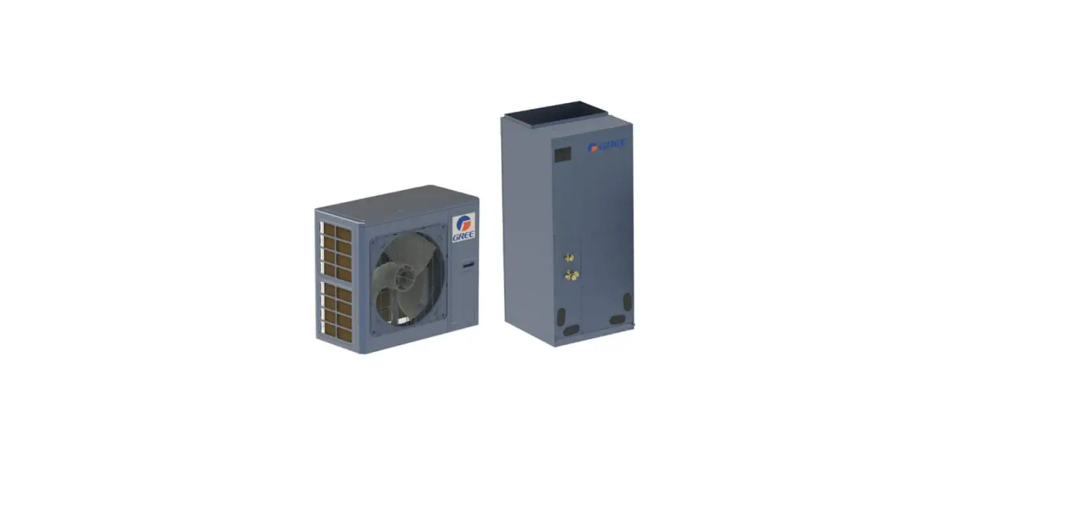
GREE FLEXX36HP230V1AO Flexx Cold Climate Heat Pump
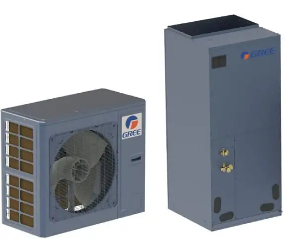
Cold Climate Heat Pump
Thank you for choosing our product. Please read this Quick Start Guide carefully before operation and retain it for future reference. To download an electric version of this manual visit greecomfort.com
PLEASE READ FIRST
Although very similar to traditional unitary heat pump systems, the FLEXX Heat Pump Systems have a few key installation differences.
- Each outdoor unit has two capacity and blower settings available on their corresponding control boards. (Detailed on the next page)
a. The 36kBtu models are rated for either 24kBtu or 36kBtu, nominal.
b. The 60kBtu models are rated for either 48kBtu or 60kBtu, nominal.
c. The efficiency ratings may change with a change in the capacity rating.
d. The outdoor and indoor capacities must match. - Both outdoor and indoor units feature service (shut-off) valves on both the liquid and gas (suction) valves.
a. The indoor unit does not contain a nitrogen charge, but a small amount (0.55lbs) of R-410A refrigerant.
b. Do not release this refrigerant into the atmosphere.
c. When evacuating (pulling a vacuum), pull from both the liquid and gas (suction) valves. This will ensure a proper evacuation has been performed and no air or other contaminants are in the refrigeration system. This will also mean proper evacuation takes less time. - The “W1” terminal activates the electric heat kit (if equipped).
a. This must be connected to the indoor and outdoor unit, and at the thermostat.
b. The heat kit is activated during defrosting by the outdoor unit’s “D” terminal. (Some models may have “W1” instead of “D.”)
c. For a heat pump application, not straight cooling or dual fuel, the “W1” control wire will connect to “W2” or “AUX” on the thermostat - This system contains PVE oil, not POE. Cross-contamination is prohibited.
a. Replace or flush existing line sets and/or coils in a retrofit application.
DO NOT DISCARD. STORE THIS INFORMATION IN A SAFE PLACE FOR FUTURE REFERENCE.
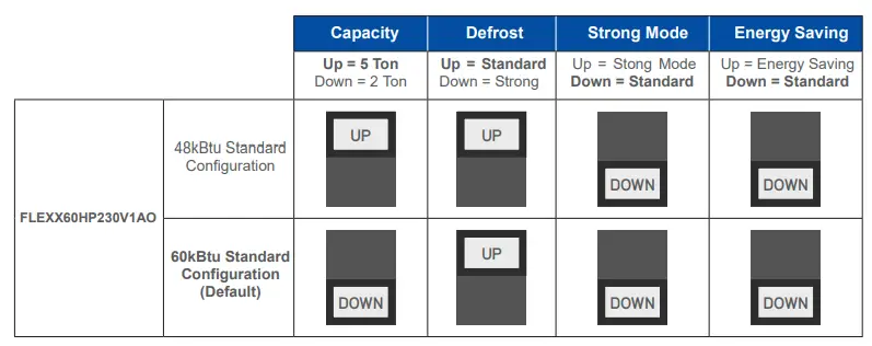
OUTDOOR UNIT DIP SWITCH SETTINGS
NOTE:
- The FLEXX outdoor units are configurable by a set of dip switches located on the main control board. The outdoor unit capacity must match the indoor unit capacity. Power must be off prior to changing the dip switch settings. The Power Mode and Energy Saving modes cannot be set simultaneously.
- These Dip Switches are located in the upper-right-hand corner of the Main Control Board.
- By default, the capacity is set at the larger capacity. Defrost, Power Mode, and Energy Saving are all set for Standard, by default.


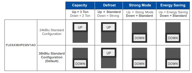
DEFROST:
Standard Defrost Mode is the default setting from the factory. The Strong Defrost Mode is used in cold but high-humidity environments such as areas near large bodies of water. If it is common practice to extend defrost timing or increase the frequency of defrost cycles in the area in which this system is installed, it is good practice to select Strong Defrost Mode before startup. In other cases where the Standard Defrost Mode has been deemed insufficient, ensure the system is in good working order, as in the outdoor coil is clean and the system is charged properly, before changing the defrost setting to Strong Defrost Mode.
STRONG MODE:
In Standard Mode, the compressor slowly ramps up in speed in an effort to provide efficient cooling and heating. When Strong Mode is enabled, the ramp-up time is reduced. In effect, the compressor will increase its speed at a higher rate. Strong Mode may be enabled if Standard Mode has been deemed insufficient by the customer. Ensure that the system is in good working order before enabling the Strong Mode.
ENERGY SAVING MODE:
In Standard Mode, the compressor slowly ramps up in speed in an effort to provide efficient cooling and heating. When the Energy Saving Mode is enabled, the compressor ramp-up time is increased. In effect, the compressor will increase its speed at a slower rate. This can increase energy efficiency and provide more dehumidification than the Standard or Strong Modes. An example of when Energy Saving Mode may be used is when the new system is replacing a system that was a half-ton smaller than the FLEXX being installed. The FLEXX is not available in 1.5, 2.5, or 3.5-ton capacities, therefore the FLEXX would be set for the next highest capacity, like 2, 3, or 4 ton, and the Energy Saving Mode would be enabled. The indoor CFM rating should also be reduced to match a normal CFM rating for the half-ton system design. This would mean the set-point would most likely be satisfied before reaching the system’s full rated nominal capacity, reducing energy usage and improving dehumidification in cooling.
NOTE: Strong Mode and Energy Saving Mode cannot be enabled at the same time. Only one mode can be enabled.
REFRIGERANT CHARGING
- It is recommended to install a new 3/8” X 3/4” line set
- If suction line is larger than 3/4” (7/8” or 1-1/8”) refrigerant must be added to accommodate the additional pipe diameter.
- Filter driers are not recommended. Follow industry best practices for refrigerant piping.
- For 7/8” suction line, add additional 0.03 oz for each foot of line set. For 1 1/8” suction line, add additional 0.11 oz for each foot of line set.
| FLEXX 2/3-Ton FLEXX36HP230V1AO | ||||
| Total Length of Line Set: | Add: | Total Length of Line Set: | Add: | |
| Less than 31 Feet | None | 96 to 98 Feet | 1 lb 7 Oz | |
| 32 Feet | 2 Oz. | 99 to 101 Feet | 1 lb 8 Oz | |
| 33 to 35 Feet | 3 Oz. | 102 to 104 Feet | 1 lb 9 Oz | |
| 36 to 39 Feet | 4 Oz. | 105 to 107 Feet | 1 lb 10 Oz | |
| 40 to 42 Feet | 5 Oz. | 108 to 110 Feet | 1 lb 11 Oz | |
| 43 to 45 Feet | 6 Oz. | 111 to 114 Feet | 1 lb 12 Oz | |
| 46 to 48 Feet | 7 Oz. | 115 to 117 Feet | 1 lb 13 Oz | |
| 49 to 51 Feet | 8 Oz. | 118 to 120 Feet | 1 lb 14 Oz | |
| 52 to 54 Feet | 9 Oz. | 121 to 123 Feet | 1 lb 15 Oz | |
| 55 to 57 Feet | 10 Oz. | 124 to 126 Feet | 2 lb | |
| 58 to 60 Feet | 11 Oz. | 127 to 129 Feet | 2 lb 1 Oz | |
| 61 to 64 Feet | 12 Oz. | 130 to 132 Feet | 2 lb 2 Oz | |
| 65 to 67 Feet | 13 Oz. | 133 to 135 Feet | 2 lb 3 Oz | |
| 68 to 70 Feet | 14 Oz. | 136 to 139 Feet | 2 lb 4 Oz | |
| 71 to 73 Feet | 15 Oz. | 140 to 142 Feet | 2 lb 5 Oz | |
| 74 to 76 Feet | 1 lb | 143 to 145 Feet | 2 lb 6 Oz | |
| 77 to 79 Feet | 1 lb 1 Oz | 146 to 148 Feet | 2 lb 7 Oz | |
| 80 to 82 Feet | 1 lb 2 Oz | 149 to 151 Feet | 2 lb 8 Oz | |
| 83 to 85 Feet | 1 lb 3 Oz | 152 to 154 Feet | 2 lb 9 Oz | |
| 86 to 89 Feet | 1 lb 4 Oz | 155 to 157 Feet | 2 lb 10 Oz | |
| 90 to 92 Feet | 1 lb 5 Oz | 158 to 160 Feet | 2 lb 11 Oz | |
| 93 to 95 Feet | 1 lb 6 Oz | 161 to 164 Feet | 2 lb 12 Oz | |
| 164 Feet is Max. Length | ||||
| FLEXX 4/5 Ton FLEXX60HP230V1AO | ||||
| Total Length of Line Set: | Add | Total Length of Line Set: | Add | |
| Less than 31Feet | None | 65 to 67 Feet | 13 Oz. | |
| 32 Feet | 2 Oz. | 68 to 70 Feet | 14 Oz. | |
| 33 to 35 Feet | 3 Oz. | 71 to 73 Feet | 15 Oz. | |
| 36 to 39 Feet | 4 Oz. | 74 to 76 Feet | 1 lb | |
| 40 to 42 Feet | 5 Oz. | 77 to 79 Feet | 1 lb 1 Oz | |
| 43 to 45 Feet | 6 Oz. | 80 to 82 Feet | 1 lb 2 Oz | |
| 46 to 48 Feet | 7 Oz. | 83 to 85 Feet | 1 lb 3 Oz | |
| 49 to 51 Feet | 8 Oz. | 86 to 89 Feet | 1 lb 4 Oz | |
| 52 to 54 Feet | 9 Oz. | 90 to 92 Feet | 1 lb 5 Oz | |
| 55 to 57 Feet | 10 Oz. | 93 to 95 Feet | 1 lb 6 Oz | |
| 58 to 60 Feet | 11 Oz. | 96 to 98 Feet | 1 lb 7 Oz | |
| 61 to 64 Feet | 12 Oz. | |||
| 98 Feet is Max. Length | ||||
COLD WEATHER STARTUP
The FLEXX outdoor unit is factory equipped with a crankcase heater.
- In outdoor temperatures below 32°F (0°C), ensure that power is applied to the outdoor unit for a minimum of 8 hours prior to startup.
- Upon power application, check the operation of the crankcase heater by removing the front access panel, opening the compressor blanket, and checking to see if the crankcase heater is hot.
- The crankcase heater ensures that liquid refrigerant is not present in the compressor before startup.
- Liquid refrigerant is not compressible and will force the compressor oil out of the compressor.
- This will damage the compressor
INSTALLATION TIP:
To make the best use of the 8 hour preheat, try the following:
- Set the outdoor and indoor units
- Install the refrigerant piping
- Leak check
- Pull a 500 micron vacuum
- Connect line voltage to the outdoor unit
- Weigh in additional charge, if needed
- Open the indoor and outdoor shutoff valves
- Power on the outdoor unit
- Complete all other installation items once power is applied to the outdoor unit
ELECTRIC HEAT KIT PRECAUTIONS
ANY FIELD WIRING, IF PRESENT, ON L1/L2 MUST BE DISCONNECTED PERMANENTLY PRIOR TO HEAT KIT INSTALLATION! ALL POWER FOR THE AIR HANDLER WILL BE PROVIDED THROUGH THE HEAT KIT BREAKER! FAILURE TO DISCONNECT ALL FIELD WIRING ON THE L1/L2 TERMINAL CAN RESULT IN FIRE!
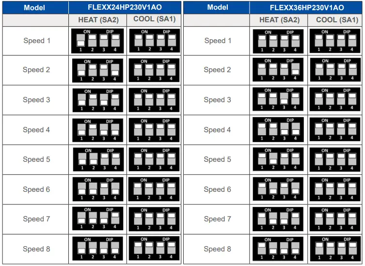
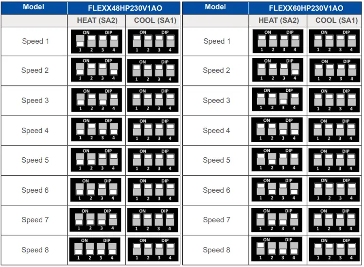
AIR HANDLER DIP SWITCH SETTINGS
NOTE:
- The FLEXX Air Handlers are configurable by a set of dip switches located on the main control board. For proper operation, ensure that the air handler blower settings match the outdoor unit capacity and ducting design. Power must be off prior to changing the dip switch settings.
- There are eight static pressure settings for the blower.
- These Dip Switches are located on the Main Control Board inside the air handler control box.
- By default, the blower is set at Speed 4.
- The dip switch settings are on the following two pages.
- As with all air handling equipment, a duct system with a design that exceeds the capabilities of the installed equipment will result in customer discomfort, limited performance, and reduced equipment life.
NOTE:
- Only the “HEAT (SA2)” dip switches are adjusted.
- The “COOL (SA1)” dip switches must remain in the “ON” position.
AIR HANDLER AIRFLOW RATINGS
The following CFM ratings are with a dry coil and included filter. For wet coil ratings, use 0.92 as the correction factor for the CFM.
| Model | FLEXX24HP230V1AO | |||||||||||
| Level | Static Pressure (In W.c.) and CFM | |||||||||||
| 0 | 0.1 | 0.15 | 0.2 | 0.3 | 0.4 | 0.5 | 0.6 | 0.7 | 0.8 | 0.9 | 1.0 | |
| Speed 1 | 1030 | 900 | 840 | – | – | – | – | – | – | – | – | – |
| Speed 2 | 1080 | 960 | 900 | 840 | – | – | – | – | – | – | – | – |
| Speed 3 | 1220 | 1120 | 1060 | 990 | 850 | – | – | – | – | – | – | – |
| Speed 4 | 1390 | 1290 | 1240 | 1180 | 1070 | 960 | – | – | – | – | – | – |
| Speed 5 | 1580 | 1490 | 1440 | 1390 | 1290 | 1180 | 1090 | 970 | 830 | – | – | – |
| Speed 6 | 1720 | 1640 | 1600 | 1550 | 1450 | 1360 | 1250 | 1130 | 960 | – | – | – |
| Speed 7 | 1800 | 1730 | 1680 | 1630 | 1550 | 1460 | 1370 | 1270 | 1150 | 970 | 830 | – |
| Speed 8 | 1850 | 1820 | 1790 | 1740 | 1660 | 1580 | 1500 | 1410 | 1340 | 1200 | 1080 | 930 |
| Model | FLEXX36HP230V1AO | |||||||||||
| Level | Static Pressure (In W.c.) and CFM | |||||||||||
| 0 | 0.1 | 0.15 | 0.2 | 0.3 | 0.4 | 0.5 | 0.6 | 0.7 | 0.8 | 0.9 | 1.0 | |
| Speed 1 | 1150 | 1050 | 950 | 880 | – | – | – | – | – | – | – | – |
| Speed 2 | 1200 | 1100 | 1000 | 940 | 850 | – | – | – | – | – | – | – |
| Speed 3 | 1380 | 1260 | 1200 | 1100 | 950 | – | – | – | – | – | – | – |
| Speed 4 | 1550 | 1460 | 1390 | 1310 | 1160 | 1010 | 830 | – | – | – | – | – |
| Speed 5 | 1710 | 1650 | 1600 | 1560 | 1480 | 1400 | 1310 | 1210 | 1080 | 930 | – | – |
| Speed 6 | 1840 | 1800 | 1750 | 1710 | 1640 | 1590 | 1500 | 1420 | 1330 | 1220 | 1100 | 960 |
| Speed 7 | 1870 | 1830 | 1810 | 1800 | 1760 | 1690 | 1620 | 1520 | 1440 | 1350 | 1250 | 1150 |
| Speed 8 | 1900 | 1860 | 1840 | 1830 | 1790 | 1720 | 1660 | 1600 | 1540 | 1440 | 1320 | 1220 |
| Model | FLEXX48HP230V1AO | |||||||||||
| Level | Static Pressure (In W.c.) and CFM | |||||||||||
| 0 | 0.1 | 0.15 | 0.2 | 0.3 | 0.4 | 0.5 | 0.6 | 0.7 | 0.8 | 0.9 | 1.0 | |
| Speed 1 | 1640 | 1500 | 1450 | 1350 | – | – | – | – | – | – | – | – |
| Speed 2 | 1680 | 1560 | 1500 | 1380 | 1300 | – | – | – | – | – | – | – |
| Speed 3 | 1810 | 1690 | 1620 | 1550 | 1380 | – | – | – | – | – | – | – |
| Speed 4 | 1930 | 1830 | 1770 | 1710 | 1580 | 1430 | 1280 | – | – | – | – | – |
| Speed 5 | 2200 | 2110 | 2040 | 1980 | 1860 | 1720 | 1620 | 1490 | 1380 | – | – | – |
| Speed 6 | 2240 | 2190 | 2145 | 2100 | 2010 | 1870 | 1750 | 1615 | 1500 | 1380 | – | – |
| Speed 7 | 2280 | 2240 | 2200 | 2180 | 2130 | 2080 | 2000 | 1880 | 1750 | 1600 | 1420 | – |
| Speed 8 | 2300 | 2260 | 2220 | 2190 | 2140 | 2090 | 2040 | 1980 | 1930 | 1800 | 1700 | 1550 |
| Model | FLEXX60HP230V1AO | |||||||||||
| Level | Static Pressure (In W.c.) and CFM | |||||||||||
| 0 | 0.1 | 0.15 | 0.2 | 0.3 | 0.4 | 0.5 | 0.6 | 0.7 | 0.8 | 0.9 | 1.0 | |
| Speed 1 | 1660 | 1540 | 1470 | 1400 | – | – | – | – | – | – | – | – |
| Speed 2 | 1850 | 1720 | 1650 | 1600 | 1400 | – | – | – | – | – | – | – |
| Speed 3 | 1920 | 1800 | 1730 | 1650 | 1480 | 1315 | – | – | – | – | – | – |
| Speed 4 | 2110 | 2000 | 1950 | 1860 | 1760 | 1640 | 1490 | 1325 | – | – | – | – |
| Speed 5 | 2250 | 2200 | 2190 | 2140 | 2040 | 1930 | 1800 | 1670 | 1520 | 1370 | – | – |
| Speed 6 | 2260 | 2220 | 2200 | 2170 | 2090 | 2010 | 1910 | 1760 | 1650 | 1550 | 1430 | 1380 |
| Speed 7 | 2300 | 2260 | 2230 | 2200 | 2150 | 2115 | 2050 | 1990 | 1920 | 1840 | 1750 | 1660 |
| Speed 8 | 2320 | 2280 | 2250 | 2230 | 2190 | 2140 | 2080 | 2040 | 2000 | 1950 | 1920 | 1890 |
- U.S. CONTACT INFORMATION TRADEWINDS CLIMATE SYSTEMS, LLC
- E-mail: [email protected]
- Contractor Support: 888-850-7928 I Mon-Fri 8 AM – 5 PM EST
- GREECOMFORT.COM


