Munters RSLC Silo Weighing Scale-Junction Box Instruction Manual

Manual for use and maintenance
RSLC and RJB-6
Silo Weighing Scale/Junction Box
RSLC Load Cell and RJB-6Junction Box Manual for use and maintenance
Revision: N.1.4 of 09/2022 Product Software: N/A
This manual for use and maintenance is an integral part of the apparatus together with the attached technical documentation.
This document is destined for the user of the apparatus: it may not be reproduced in whole or in part,
committed to computer memory as a file or delivered to third parties without the prior authorization of
the assembler of the system.
Munters reserves the right to effect modifications to the apparatus in accordance with technical and legal developments
1 Introduction
1.1 Disclaimer
Munters reserves the right to make alterations to specifications, quantities, dimensions etc. for production or other reasons, subsequent to publication. The information contained herein has been
prepared by qualified experts within Munters. While we believe the information is accurate and complete, we make no warranty or representation for any particular purposes. The information is
offered in good faith and with the understanding that any use of the units or accessories in breach ofthe directions and warnings in this document is at the sole discretion and risk of the user.
1.2 Introduction
Congratulations on your excellent choice of purchasing an RSLC Load Cell and RJB-6 Junction Box! In order to realize the full benefit from this product it is important that it is installed, commissioned and operated correctly. Before installation or using the units, this manual should be studied carefully. It is also recommended that it is kept safely for future reference. The manual is intended as a reference for installation, commissioning and day-to-day operation of the Munters equipment.
1.3 Notes
Date of release: July 2010
Munters cannot guarantee to inform users about the changes or to distribute new manuals to them.
NOTE All rights reserved. No part of this manual may be reproduced in any manner whatsoever without the expressed written permission of Munters. The contents of this manual are subject to change without notice. © Munters AB, 2018 5
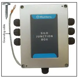
2 RJB-6 Installation
Munters RJB-6 enables connecting up to eight load cells to a single controller. This section details
how to mount and wire the RJB-6.
- Remove the four cover screws to open the unit

- Figure 1: Opening the RJB-6 Cover
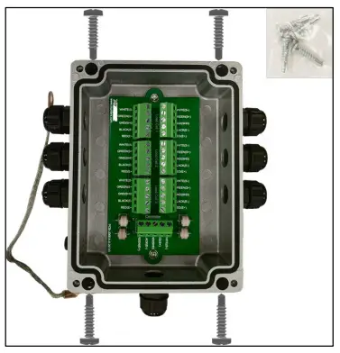
- Using a drill and the supplied screws, attach the RJB-6 to a silo leg

Figure 2: RJB-6 Mounting - Close the unit.
- Attach the grounding cable to a silo leg.

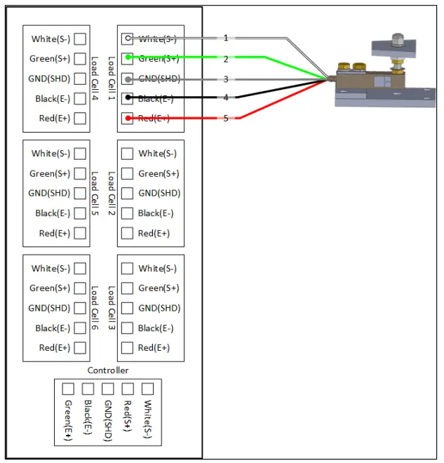
- Cable: Board
o White – White
o Red – Red
o Black – Black
o Green – Green
o Connect the shield wire to the GND(SHD) port
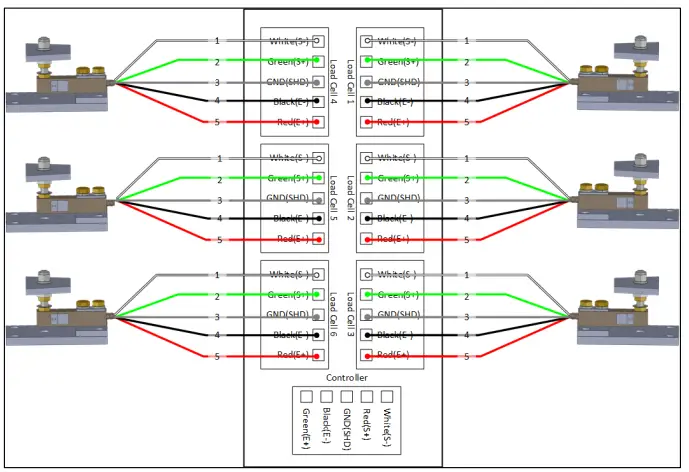
Figure 5: RJB – Six RSLCs Wiring Figure 5 key
1 If there are eight load cells, add the two remaining cells along with load cells 1 and 2
6. Connect the relevant controller cables to the “Controller” terminal block within the RJB
junction box. The connection colors of this cable are direct connection.
NOTE Refer to the specific controller manual for details on wiring the RJB-6 to the controller.
• Cable: Board
o White – White
o Red – Red
o Black– Black
o Green – Green
3 RSLC Installation
The following sections detail how to install the:
- RSLC-4 supports up to 4,000 pounds (per leg)
- RSLC-10 supports up to 10,000 pounds (per leg)
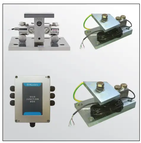
- RSLC-25 supports up to 25,000 pounds (per leg) Place load cells under each silo leg.

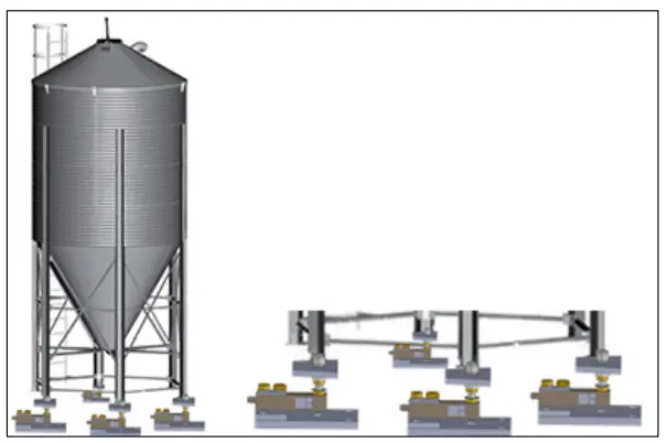
Figure 6: Silo Legs and Load Cells
The RSLC units comes with a grounding cable that, if required, can be run from one silo leg to a grounding rod.

Figure 7: Grounding cable
3.1 RSLC-4
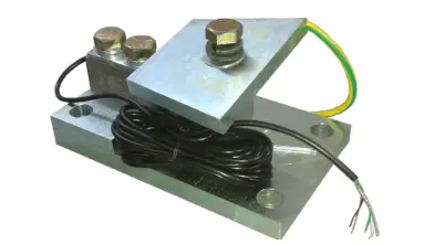
Figure 8: RSLC-4 Unit
- RSLC-4 Installation
- RSLC-4 Specifications
3.1.1 RSLC-4 Installation
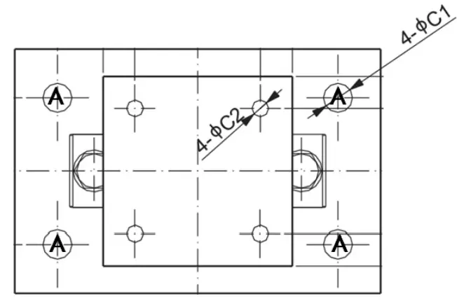
Figure 9: RSLC-4 Plate Dimensions
- Figure 9 illustrates the RSLC-4 plate. Drill four holes into the concrete base as indicated (A).
- Wire the Load Cells to the RJB-6.
- 1.2 RSLC-4 Specification

Table 1: RSLC-4 Specifications
| Parameter | Value |
| Full Scale Output | 3.0 mV/V±0.25% |
| Zero Balance | ±0.02 mV/V |
| Input Resistance | 400Ω±20 for kg; 350Ω±7 for lb. |
| Output Resistance | 350Ω±3 |
| Parameter | Value |
| Element Material | Alloy Steel, Nickel Plated |
| Recommended Excitation | 10V (15V Maximum) |
| Insulation Resistance | >2[50V DC]GΩ |
| Compensated Temperature Range | -10oC to 50oC / 14oF to 122oF |
| Safe Overload | 150% of full scale |
| Breaking Overload | 300% of full scale |
| Seal Type / IP Rating | Cap.≤300kg/500lb: Environmentally Sealed / IP66 Cap.≥500kg/1Klb: Environmentally Sealed / IP67 |
Figure 10 and Table 2 detail the RSLC-4 Load Cell dimensions
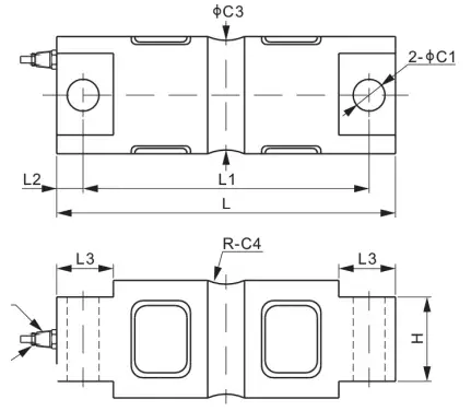
Figure 10: RSLC-4 Load Cell Dimensions
Table 2: RSLC-4 Load Cell Dimensions Details
| Letter | C1 | C2 | H | H1 | L | L1 | L2 | L3 | L4 | W |
| Dimensions (in) | 0.53 | 0.81 | 1.25 | 0.60 | 5.12 | 2.25 | 3.00 | 1.00 | 0.62 | 1.25 |
| Dimensions (mm) | 13.5 | 20/6 | 31.8 | 15.2 | 130 | 57.2 | 76.2 | 25.4 | 15.8 | 31.8 |
1.1 RSLC-10
Figure 11: RSLC-10 Unit
3.2.1 RSLC-10 Installation
3.3 RSLC-25\
Figure 13: RSLC-10 Load Cell Dimensions
Table 4: RSLC-10 Load Cell Dimensions Details
| Letter | C1 | C2 | C3 | C4 | H | L | L1 | L2 | L3 |
| Dimensions (inches) | 0.66 | 1.85 | 1.48 | 0.50 | 1.12 | 8.12 | 6.87 | 0.62 | 1.44 |
| Dimensions (mm) | 16.7 | 49.5 | 37.6 | 12.7 | 28.4 | 206.2 | 174.6 | 15.8 | 36.6 |
3.4 Environmental Protection
 Recycle raw materials instead of disposing as waste. The controller, accessories and packaging should be sorted for environmental-friendly recycling. The plastic components are labeled for categorized recycling.
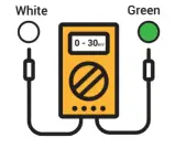
4.2 Load Cell Test Procedure
To perform a load-cell test procedure, disconnect the load cell from any load and test following points:
- Disconnect the white and green wires from each load cell at the Junction Box.
- Measure the voltage between the green and the white wires with a DC voltmeter, at each load cell.
o The voltage should be 0 to 30mV proportional to the silo weight.
o The voltage difference between load cells should not exceed 3mV.