![]()
![]() XX7V1A1NAM12: NO
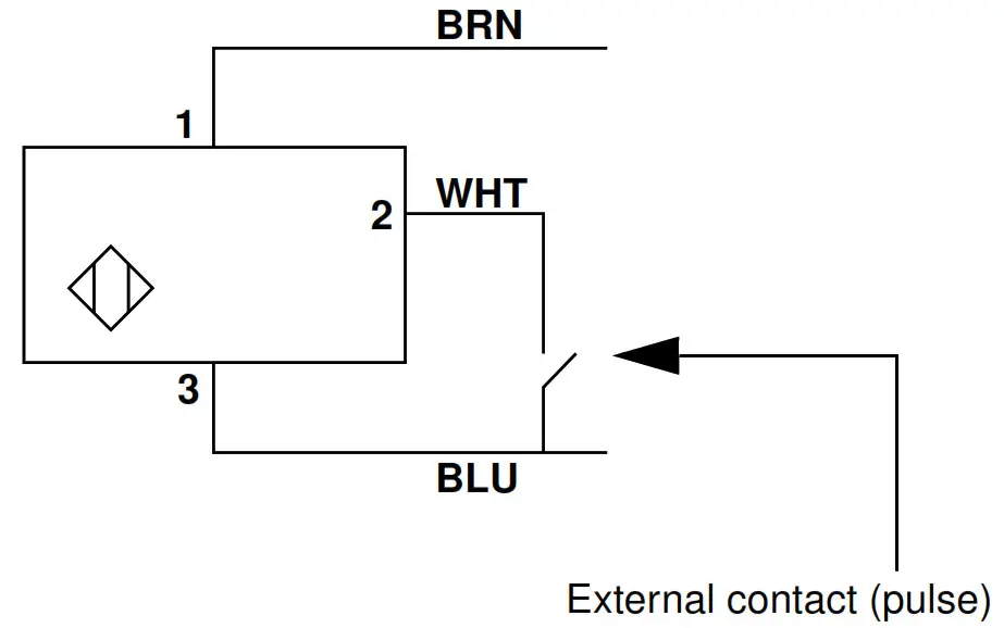
XX7V1A1NAM12: NO
NPN output; Sortie NPN
Ultrasonic Sensors
Installation Guide
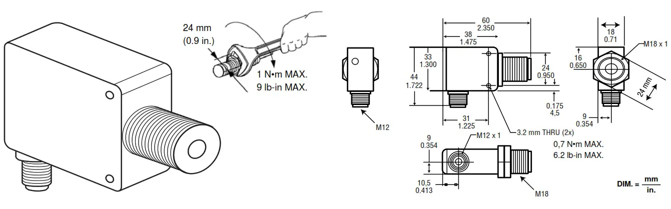
Mounting
Operation
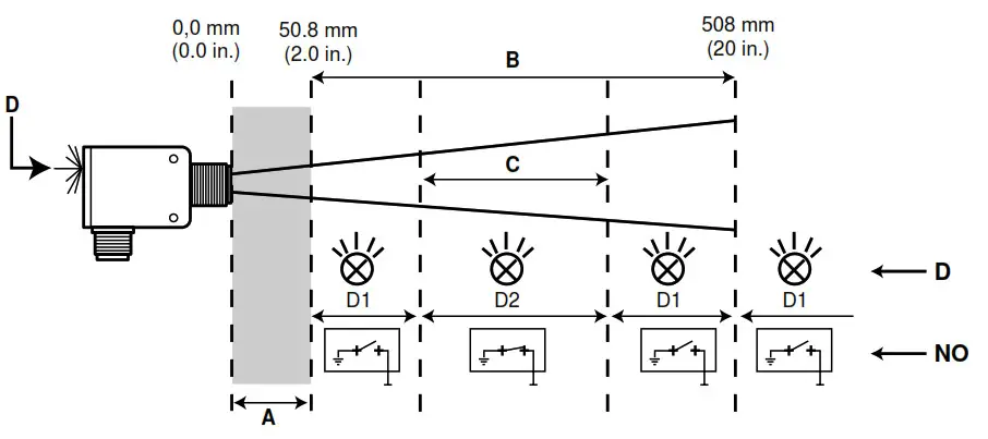
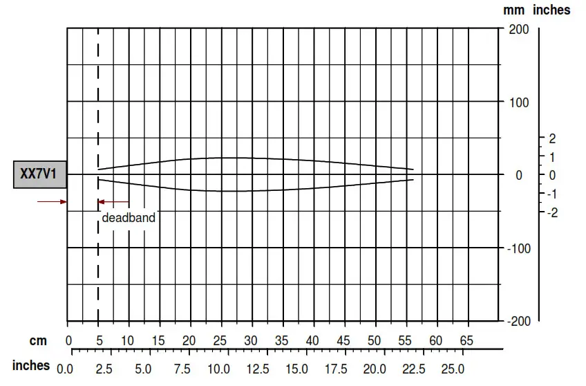
| A | Deadband: erratic operation within this range |
| B | Sensing range |
| C | Sensing window |
| D | Bicolor LED |
| D1 | Bicolor LED is green when an object is not sensed. |
| D2 | Bicolor LED is amber when an object is sensed. |
| NO | Normally open output |
 WARNING
DETECTION OUTSIDE THE SENSING WINDOW
Do not set up this product to detect an object within the deadband.
Unintended operation can result in death, serious injury, or equipment damage.
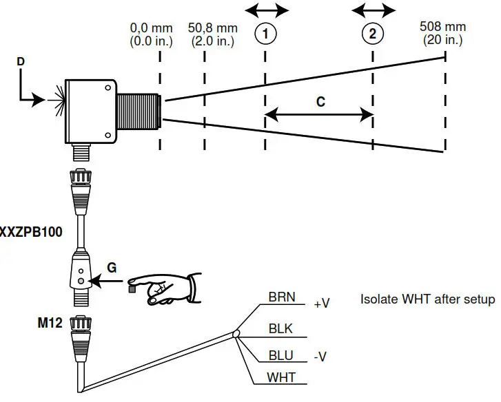
Setting the Sensing Window Using Accessory XXZPB100
Manual Setup (without XXZPB100)
Setting the Sensing Window
NOTE: For manual setup, use the external contact in place of button G.
- Install accessory XXZPB100.
- Remove all objects from the sensor’s field of detection.
- Align the sensor with the object to be detected.
- Push and hold the setup button (G) until the bicolor LED (D) rapidly flashes green.
- Release the button. The bicolor LED continues to flash green.
- Within 30 s, insert an object into position 1, then push and release the setup button. The bicolor LED flashes amber.
- Within 30 s, insert an object into position 2, then push and release the setup button. The bicolor LED flashes green, then turns steady amber The device is set up properly if:
– The LED turns amber when an object is sensed inthe window.
– The LED turns green when an object is not sensed.
To reset the sensor, repeat Step 4.
When setup is complete, disconnect power and remove accessory XXZPB100.
Reconnect power to the sensor.
Wiring
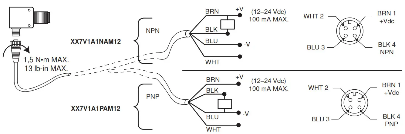
| BRN | Brown |
| BLK | Black/Output |
| WHT | White/ Teach Input |
| BLU | Blue/DC Com |
| NPN | Sinking |
| PNP | Sourcing |
Beam Plot
Cabling Accessories
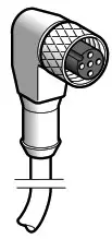 | 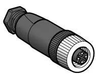 | 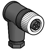 | |
| XZCP1141L2 (2 m / 6.6 ft) XZCP1141L5 (5 m / 16.4) XZCP1141L10 (10 m / 32.8) | XZCP1241L2 (2 m / 6.6 ft) XZCP1241L5 (5 m / 16.4) XZCP1241L10 (10 m / 32.8) | XZCC12FDM40B XZCC12FDP40B | XZCC12FCM40B XZCC12FCP40B |
Electrical equipment should be installed, operated, serviced, and maintained only by qualified personnel. No responsibility is assumed by Schneider Electric for any consequences arising out of the use of this material.
© 2004 Schneider Electric All Rights Reserved
![]() 30072-450-14
30072-450-14


