
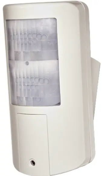
RISCO 5IN2849 Wired Outdoor DT Curtain Detector
Instruction
Wired Outdoor DT Curtain Detector Installation Instructions
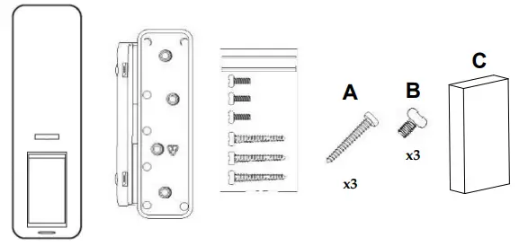
What’s in the box / IT Materiale incluso nella confezione
Curtain – Side View / IT Tenda – Vista laterale

BUS MODE
Panel Teol
Description
RISCO Outdoor DT Curtain detector has been designed to provide enhanced 24-hour outdoor protection, with Active IR Anti-mask, Integrated Dual Technology that combines K-Band microwave with PIR sensor and light sensor to minimize false alarms.
Features include
- Selectable detection coverage of up 12m, 5°
- K-Band Microwave detection
- Active IR Anti-mask
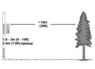
- Various mounting heights 1.8-3m
- Optional 90° installation bracket (included)
- Designed for outdoor installation, UV resistance, IP 65
- Tamper protection
Installation
Preliminary Considerations
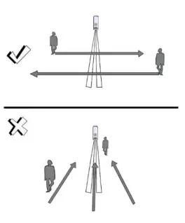
Select the mounting location for the best coverage of the area that is to be protected. Avoid pointing the detector in the direction of moving objects (such as, swaying trees and bushes).
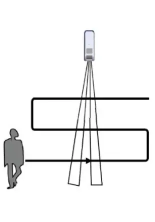
PIR Coverage Pattern
For optimal detection results, install the detector at a height of 2.4 m
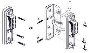
Mount the Bracket on the Wall
(4, 6a, and 6b)
Setting the Detector Mode
- Standalone
- DIP SW 6 is OFF
- Terminal wiring as in Step 5a
RISCO BUS Mode
- DIP SW 6 is ON
- Wiring: (see Figure 9)
- terminal (Detector power)
- Connecting YEL / GRN – Detector BUS
- Continue to Step 6
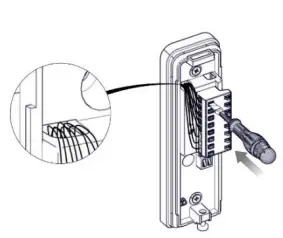
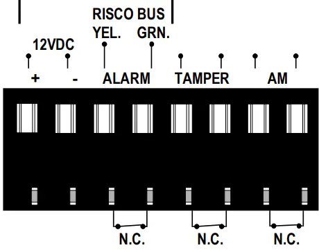
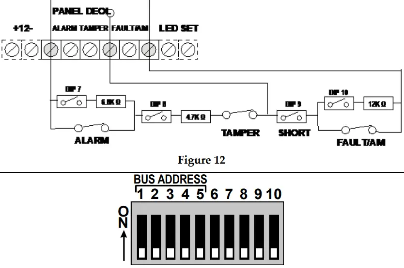
Connecting the Terminal Wiring (Standalone Mode)
Connect the terminal wiring according to Figures 5 & 9
| Terminal | Descripción | |
| + – | +12 V CC, – GND | |
| ALARM YEL GRN | Relé de alarma N.C | YEL/GRN (RISCO BUS) |
| NOTA: tal como lo define el interruptor DIP SW 6 | ||
| TAMPER | Interruptor del tamper N.C | |
| AM | Relé de alarma antienmascaramiento N.C | |
Setting DIP Switch Settings (Standalone Mode)
Set the DIP switch settings according to the table, below
| Interruptor DIP SW | Descripción | ||||
| 1 | LED: ON*: Activado / OFF: Desactivado | ||||
| Sensibilidad (PIR) | Baja | Med. | Norm. | Alta. | |
| 2 | OFF | ON | OFF* | ON | |
| 3 | OFF | OFF | ON* | ON | |
| 4 | Antienmascaramiento: ON: Activado / OFF*: Desactivado | ||||
| 5 | Para su uso futuro | ||||
| 6 | Modo: OFF*: Relé / ON: BUS (ver Definición del ID del BUS) | ||||
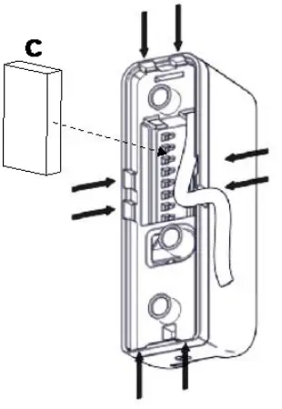
- Available Wiring Channels
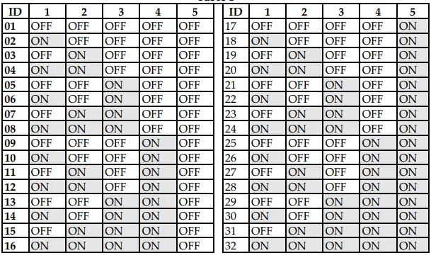
- Defining the BUS ID (BUS Mode)
- This step is only relevant for detectors that are connected to the RISCO BUS.
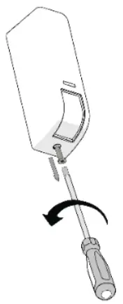
- Securing the Detector to the Bracket (See Figures 7 & 8)
- Registering the Detector into the System
- Adding the BUS Detector (LightSYS/ProSYS Plus)
Select Installer menu
- Install
- BUS Device
- Automatic.
- The system automatically searches for the detector’s BUS ID and assigns a zone (according to the defined DIP switch settings.
- Click OK to confirm.
- Configure the BUS detector parameters:
- Zones
- Parameters
- By Category
- Advanced
- BUS Zone Parameters
- lights / ProSYS Plus Installation Manual).
- For LightSYS Version 5.92 and above / ProSYS Plus Version 1.3.0.x and above.
- Exit the Installer menu.
Walk Test
Walkthrough the entire protected area and observe the LEDs to confirm full coverage (see LED Status). When complete, secure the detector with screw (see Figure 11).
LED Status
| LED | State | Description |
| Red | Blinks once | Alarm |
| Flashing | Communication error with the system (BUS Mode only) | |
| Green | Blinks once | Microwave detection |
| Orange | Blinks once | PIR detection |
| Flashing | AM (Anti mask) detection | |
| All LEDs | Flashing (consecutively) | Unit initialization upon power-up |
Self-Test
Every hour the detector performs an internal self-test for both PIR and MW channels. A fault detected in the self-test will be indicated by a momentary open anti-mask relay (in relay mode) or by a corresponding message in the panel (in BUS mode).
Technical Specifications
| Parameter | Description |
| Power | 12VDC |
| Current Consumption: Standalone Mode Bus Mode | 15 mA 10 mA |
| Power Output | 24 GHz: 100mW max. |
| Operating Temperature | -20°C to 60°C (-4°F to 140°F) |
| Storage Temperature | -25°C to 70°C (-13°F to 158°F) |
| Humidity Range | Average relative humidity: 90% IP65 |
| Weight | 107 grams (3.77 oz.) |
| Dimensions (LxHxD) | 123 x 35 x 49 mm (4.84 x 1.38 x 1.92“) |
| Frequency | 24 GHz |
Ordering Information
| P/N | Description |
| RK107DTB000A | Wired Curtain DT AM, Bus |


