i-therm BL-44 Batch Length and Preset Counter User Manual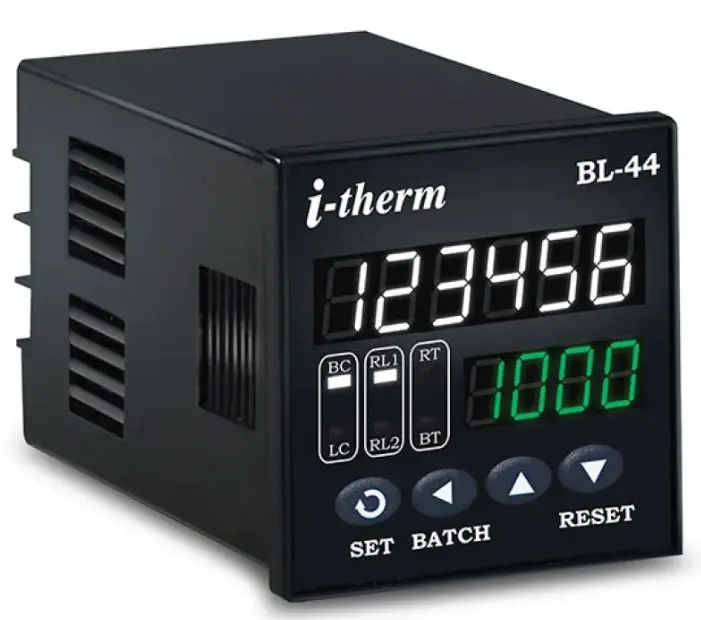
Overview
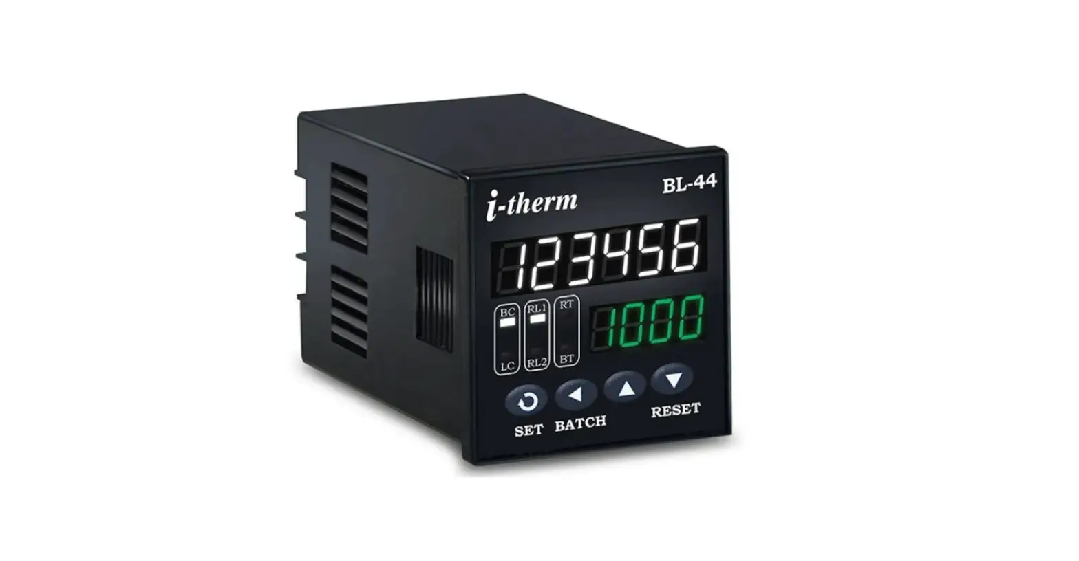
BL – 44 (48 X 48)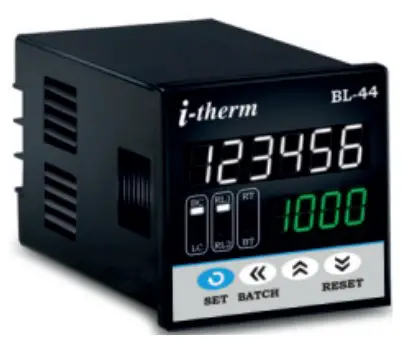
BL – 77 (72 X 72)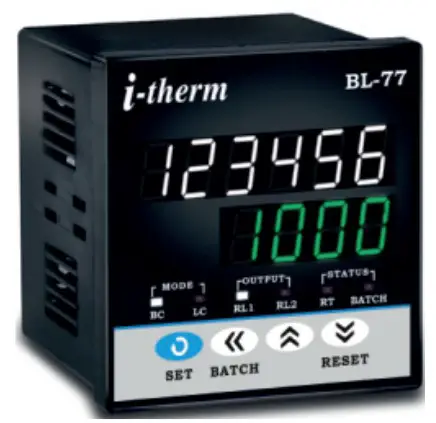
BL – 99 (96 X 96)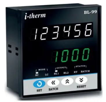
Specifications
Display : 10 Digit 7 segment LED
| Model no. | BL-44 | BL-77 | BL-99 | Display Colour |
| Display height (PV) | 0.30” | 0.39” | 0.56” | White |
| Display height (SV) | 0.24” | 0.39” | 0.56” | Green |
- LED Indication :
a) Mode LEDs
b) Output LEDs
c) Status LEDs - Range : Ref. SET Mode
- Accuracy : 0.05% Full Scale
- Outputs :
a) Two 5Amp @ 230VAC Relay
b) Buzzer Output - Memory : Non-Volatile (Flash)
- Memory Retention: Up to 10 years
- Supply : 90 to 270 VAC
- Sensor Supply : 12VDC (+10%) @ 30mA
- Mounting : Panel
- Housing : ABS Plastic
- Operating Temp. : 0 ~ 55°C
- Humidity : 95% RN(Non Condensing)
- Mechanical Dimension : See Table:1 (On Page 2)
Configuration Parameters
- Count Mode :
a) Batch Type
b) Length Type
c) Preset Type - Input Frequency :
a) Very Low b) Low
c) Medium d) High
e) Very High - Operating Mode :
a) Mode 1}
Ref. Configuration Mode
b) Mode 2 - Front Reset : Enable / Disable (Selective)
- Output 2 Function :
a) As 2nd Set Point
b) As Batch Output
c) As Auxiliary Output
d) Output is Off - Lower Display :
a) RPM
Only in Preset Type
b) Blank - Leading Zero : Enable / Disable (Selective)
- User Lock : It can be Set Between 1 to 9999
SAFETY INSTRUCTION
This controller is meant for Batch & Length counter applications. It is important to read the manual prior to installing or commissioning of controller. All safety related instruction appearing in this manual must be followed to ensure safety of the operating personnel as well as the instrument.
GENERAL
- The controller must be configured correctly for intended operation. Incorrect configuration could result in damage to the equipment or the process under control or it may lead personnel injury.
- The controller is generally part of control panel and in such a case the terminals should not remain accessible to the user after installation.
MECHANICAL
- The Controller in its installed state must not come in close proximity to any corrosive/combustible gases, caustic vapors, oils, steam or any other process by products.
- The Controller in its installed state should not be exposed to carbon dust, salt air, direct sunlight or radiant heat.
- Ambient temperature and relative humidity surrounding the controller must not exceed the maximum specified limit for proper operation of the controller.
- The controller in its installed state must be protected against excessive electrostatic or electromagnetic interferences.
Ventilation holes provided on the chassis of the instrument are meant for thermal dissipation hence should not be obstructed in the panel.
ELECTRICAL
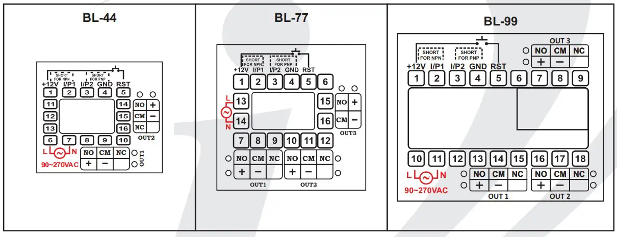
- The controller must be wired as per wiring diagram & it must comply with local electrical regulation.
- Care must be taken not to connect AC supplies to low voltage sensor input.
- Circuit breaker or mains s/w with fuse (275V/1A) must be installed between power supply and supply terminals to protect the controller from any possible damage due to high voltage surges of extended duration.
- Circuit breaker and appropriate fuses must be used for driving high voltage loads to protect the controller from any possible damage due to short circuit on loads.
- To minimize pickup of electrical noise, the wiring for low voltage DC and sensor input must be routed away from high current power cables. Where it is impractical to do this, use shielded ground at both ends.
- The controller should not be wired to a 3-Phase supply with unearthed star connection. Under fault condition such supply could rise above 264 VAC which will damage the controller.
- The Electrical noise generated by switching inductive loads might create momentary Fluctuation in display, alarm latch up, data loss or permanent damage to the instrument. To reduce this use snubber circuit across the load.
CAUTION:- To prevent the risk of electrical shock, switch off the power before making/removing any connection or removing the controller from its enclosure.
Mechanical Installation
The label on the controller identifies the Model, serial number and wiring connections.
OVER ALL DIMENSIONS & PANEL CUT OUT (IN MM)
MODEL:- BL-44 / BL-77 / BL-99
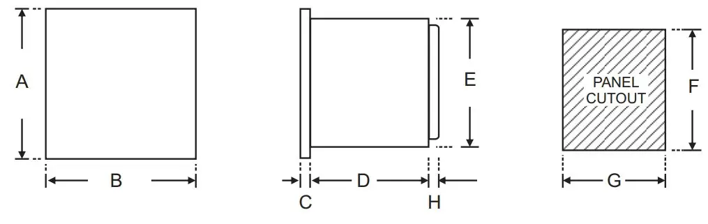
TABLE : 1
| Dim Model | A | B | C | D | E | F | G | H |
| BL – 44 | 48 | 48 | 8 | 75 | 43 | 44 | 44 | 9 |
| BL – 77 | 72 | 72 | 10 | 65 | 66 | 68 | 68 | 9 |
| BL – 99 | 96 | 96 | 10 | 45 | 89 | 92 | 92 | 9 |
Installation Guidelines:-
- Prepare the cut-out with proper dimension as shown in figure.
- Remove clamp from controller.
- Push the controller through panel cut-out and secure the controller in its place by tightening the side clamp
Typical Application
| BL-44 / BL-77 / BL-99 | ||
| PROXIMITY (PNP) | PROXIMITY (NPN) | CONTACT / SWITCH |
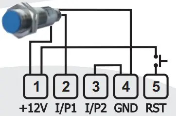 | 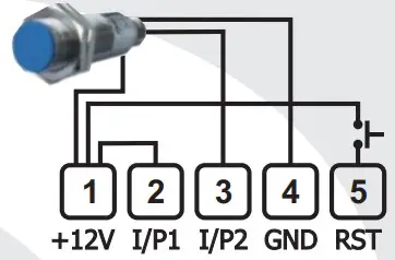 | 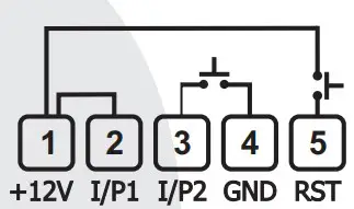 |
Electrical Installation
Front panel layout
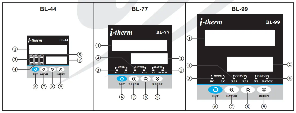
Front panel layout function:-
| No. | Names | Functions |
| 1 | Upper Display | It will display 1)In Run Mode, Total count for Batch type, Length for Length type & Running Count for Preset Type. 2) Sub Parameter in Set Mode & Configuration Mode. |
| 2 | Lower Display | It will display 1) Running Count in Batch type, Speed(Meter/Min) in Length type & RPM in Preset type in Run Mode. 2) Parameter in Set Mode & Configuration mode. |
| 3 | Mode LEDs | 1) In Batch Type BC (Batch Counter) LED will turn On.2) In Length Type LC(Length Counter) LED will turn On.3) In Pre Set Type both Modes LEDs are off. |
| 4 | Output LEDs | 1) RL1 Glows when OP1 is ON.2) RL2 Glows when OP2 is ON. |
| 5 | Status LEDs | 1) RT LED flashes when Auto reset time is running.2) BATCH LED flashes in View mode. |
| 6 | Set Key | (1) For count Setting. (2) To access Configuration mode with UP Key. (3)To scroll the parameter & to store its value. |
| 7 | Shift Key | 1) To select the particular digit for increment and decrement. 2) To go in View mode. |
| 8 | Up Key | 1) To go in Configuration mode with SET Key. 2) To increase/alter parameter value. |
| 9 | Down Key | (1) To decrease / alter parameter value in program mode. (2) To Reset the Running count & Length by single click. 3) To Reset Total Count & Batch Count(In View Mode) by pressing Down key for 3sec. |
Run Mode:-
| Para Meter | Upper Display | Lower Display | Description |
| Run Mode in Batch Type | |||
| Total & Run Count |  |  | In Run Mode for Batch Type, Lower display shows ‘Running Count’ & the upper display shows the ‘Total count’. If Running count & Set count is equal Relay 1 will Turn on, Relay will turn off depending on mode selected. If Total Count Equal to “999999″ it will be reset to zero on Next input pulse. If ‘Front reset’ is enable, Running count can be reset by pressing Reset/Down key once. Total Count can be reset by pressing & holding Reset/Down key for 3Sec. |
| Run Mode in Length Type | |||
| Total Length & Speed |  |  | In Run Mode for Length Type, Lower display shows ‘Seed in Meter/Min’ & the upper display shows ‘Length in Meter’. If Length & Set count is equal Relay 1 will Turn on, Relay will turn off depending on mode selected. If ‘Front reset’ is enable, Length can be reset by pressing Reset/Down key once. |
| Run Mode in Preset Type | |||
| Running Count & RPM |  | 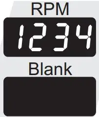 | In Run Mode for Preset Type, Lower display shows ‘RPM Value’ or ‘it will be Blank’ as per LDSP option Selected & the upper display shows the ‘Running Count’. If Running count & Set count is equal Relay 1 will Turn on, Relay will turn off depending on mode selected. If ‘Front reset’ is enable, Running count can be reset by pressing Reset/Down key once. |
View Mode:- To access View Mode press SHIFT key once.
| Para Meter | Upper Display | Lower Display | Description |
| View Mode in Batch Type | |||
| Batch Count |  |  | In Run mode, Press ‘SHIFT’ key to view Bach count. ‘Running Count’ will be displayed on the lower display & value of ‘Bach count’ will be displayed on the upper display. The Bach led flashes every 500ms to indicate’ view mode’. If Front Reset is enabled than the Bach count can be reset by pressing the Reset/Down key for 3 sec. Press ‘SHIFT’ key or wait for 5 sec to exit this mode. |
| View Mode in Length Type & Preset Type | |||
| Batch Count |  |  | In Run mode, Press ‘SHIFT’ key to view Bach count. ‘b.Cnt’ message will be displayed on the lower display & value of ‘Bach count’ will be displayed on the upper display. The Bach led flashes every 500ms to indicate’ view mode’. If Front Reset is enabled than the Bach count can be reset by pressing the Reset/Down key for 3 sec. Press ‘SHIFT’ key or wait for 5 sec to exit this mode. |
Set Mode:- To access the Set Mode press SET key once.
Press SET key to store the current parameter & move on to the next parameter.
| Para Meter | Upper Display | Lower Display | Range | Description | Default |
| Set Mode in Batch Type | |||||
| Set Count |  |  | 1 to9999Count | In RUN mode, Press ‘Set’ key to set count value. ‘S.CNT’ will be displayed on lower display & last stored/default value of ‘set count’ will be displayed on upper display. User can change this value by using Up/Down/Shift key. Press ‘’Set’ key to store Set value & move to next parameter. | 1001 |
| Set Count – Off |  |  | 1 to9999Count | This parameter will appears only if Batch Mode in Mode-2 is selected. ‘OF.SC’ will displayed on lower display & last stored value of ‘set count-Off’ will displayed on upper display. User can change this value by using Up/Down/Shift key. Press set key to store count value & move to next para.(Note:- Set Count-Off value should be always grater than Set Count). | 1002 |
| Set Count 2 |  |  | 1 to9999Counts | This parameter appears only if ‘Output 2 function as Set Count 2’ is selected in Configuration. ‘S.Ct2’ will be displayed on lower display & last stored/default value of ‘set count 2′ will be displayed on upper display. User can change this value by using Up/Down/Shift key. Press ‘’Set’ key to store Set value & move to next parameter. Set count 2 should always be less than Set Count. | 1000 |
| Set Batch |  |  | 1 to9999Batch | This parameter appears only if ‘Output 2 function as Batch’ is selected in Configuration. ‘S.BCH’ will be displayed on the lower display & last stored/default value of ‘Bach’ will be displayed on the upper display. This value can be changed by using Up/Down/Shift key. Press the ‘set’ key to store the desired value & move to next parameter. | 1000 |
| Set Mode in Length Type | |||||
| Set Meter |  |  | 0.1 to 99999.9 Meter | In RUN mode, Press ‘Set’ key to set Meter value. ‘S.CNT’ will be displayed on lower display & last stored/default value of ‘Set Meter’ will be displayed on upper display. User can change this value by using Up/Down/Shift key. Press ‘set’ key to store the desired value & move to next parameter. | 101.0Meter |
| Set Meter 2 |  |  | 0.1 to 99999.9 Meter | This parameter appears only if ‘Output 2 function as Set Count 2’ is selected in Configuration. ‘S.Ct2′ will be displayed on lower display & last stored/default value of ‘Set Meter 2′ will be displayed on upper display. User can change this value by using Up/Down/Shift key. Press ‘’Set’ key to store Set value & move to next parameter. Set count 2 should always be less than Set Count. | 100.0Meter |
| Set Mode in Preset Type | |||||
| Set Count | |  | 1 to999999Counts | In RUN mode, Press ‘Set’ key to set count value. ‘S.CNT’ will be displayed on lower display & last stored/default value of ‘set count’ will be displayed on upper display. User can change this value by using Up/Down/Shift key. Press ‘’Set’ key to store Set value & move to next parameter. | 1001 |
| Set Count 2 |  |  | 1 to999999Counts | This parameter appears only if ‘Output 2 function as Set Count 2’ is selected in Configuration. ‘S.Ct2’ will be displayed on lower display & last stored/default value of ‘set count 2′ will be displayed on upper display. User can change this value by using Up/Down/Shift key. Press ‘’Set’ key to store Set value & move to next parameter. Set count 2 should always be less than Set Count. | 1000 |
| Default Parameter in Set Mode for Length & Preset Type | |||||
| Set Batch |  |  | 1 to999999Batch | This parameter appears only if ‘Output 2 function as Batch’ is selected in Configuration. ‘S.BCH’ will be displayed on lower display & last stored/default value of ‘Bach’ will be displayed on upper display. This value can be changed by using Up/Down/Shift key. Press the ‘set’ key to store the desired value & move to next parameter. | 1000 |
| Default Parameter in Set Mode for All Type | |||||
| Time |  |  | 0.01 to 99.99 Sec. | This parameter appears only if Mode 1 is selected in Configuration. ‘time’ will be displayed on lower display & Last stored value of time appears on upper display. If time value is “0.00 sec” then it will work as Latch Output & For Auto Reset Mode user can set value in between 0.01 to 99.99Sec. User can set Auto Reset time by using Up/Down/Shift key. | 1.00 Sec |
Configuration Mode
- To enter in this mode, Press and hold SET & UP key simultaneously for 3 sec.
- Press UP or DOWN key to scroll between parameter options.
- Press SET key to store the current parameter & move on to the next parameter.
| Para Meter | Upper Display | Lower Display | Description | Default | |
| Lock Code |  |  | Set this parameter to 15 (Default LOCK CODE) to access Configuration List.User has a choice to set different Lock Code in the range 1 ~ 9999 via USER LOCK CODE in Configuration List. | 0 | |
| Type | 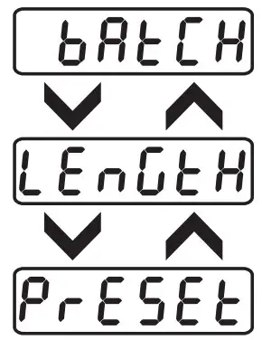 |  | User can select an option between Batch Type, Length Type & Preset Type.Batch Type : If Selected Instrument will Work as Batch Counter. | Batch | |
| Length Type : If Selected Instrument will Work as Length Counter. | |||||
| Preset Type : If Selected Instrument will Work as Preset Counter. | |||||
| Input Freq. | 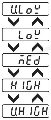 |  | User can select an option from Very Low/Low/Med/High/Very High according to the frequency of count pulse at the input terminal. This feature is useful in avoiding noise signal. | Medium | |
| Very Low Frequency:- If selected; Count Input Frequency up to 3Hz. | |||||
| Low Frequency:- If selected; Count Input Frequency up to 30Hz. | |||||
| Medium Frequency:- If selected; Count Input Frequency up to 100Hz. | |||||
| High Frequency:- If selected; Count Input Frequency up to 1KHz. | |||||
| Very High Frequency:- If selected; Count Input Frequency up to 2.5KHz. | |||||
| Mode | 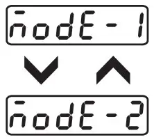 |  | This parameter will occurs only if Batch type is selected.Mode – 1: In this mode Relay1 & Buzzer will Turn Off simultaneously depending on “Time parameter” value in Set mode. | Mode – 1 | |
| Mode – 2: In this mode Relay1 & Buzzer will Turn Off depending on “Set Count – Off” Value in Set mode. | |||||
| Front Reset | 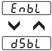 |  | ENABLE: If selected; user can reset the Running Count & Total Count by pressing Down/Reset key located at front panel. | Enable | |
| DISABLE: If selected; user can not reset the counter by pressing down key located at front panel. Only remote reset at back terminal is allowed. This feature is useful to avoid unauthorized attempt to reset the counter during run mode. | |||||
| OP2F | 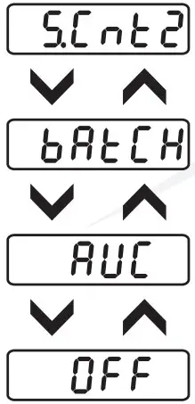 |  | Set Count 2:- If selected, Output2 used as independent Set Point. When Running Count Equal to Set Count 2 Output2 will Turn on. Output 2 will turn off, depending on Time Parameter or by pressing Down/Reset Key.Note:- This parameter will appears only if Mode as Mode 1 Selected. | Batch | |
| Batch:- If selected, Output2 used as Batch Output. When Batch Count Equal to Set Batch Output2 will Turn on. Output 2 will turn off by pressing Down/Reset Key for 3Sec. in View Mode. | |||||
| Auxiliary:- If selected, Output2 have same function as Output 1. | |||||
| Off:- If selected, Output2 is not used & cab be kept reserve for future use. | |||||
| Diameter |  |  | 0.01 to 9999.99mm | User can set desired Diameter value. ‘dIA’ will be displayed on lower display & last stored/default value of ‘Dia Meter’ will be displayed on upper display. User can change this value by using Up/Down/Shift key. Press ‘set’ key to store the desired value & move to next parameter. | 10.00mm |
| Set DP Point | 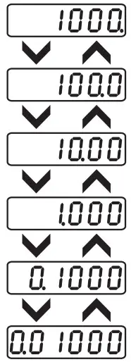 | 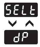 | 000000to 0.00000 | User can set position of decimal point for scale factor. The last set value of scale will appear on the upper display & the lower display will toggle b/w “SELt” & “DP”. Position of decimal point can be shifted from LSB to MSB by using the shift key. | 1000. |
| Scale Factor |  |  | 0.00001 to999999 | User can set desired Scale Factor value. ‘SCAL’ will be displayed on lower display & last stored/default value of Scale will be displayed on upper display. User can change this value by using Up/Down/Shift key. Press ‘set’ key to store the desired value & move to next parameter. | 1000 |
| Reso- lution | 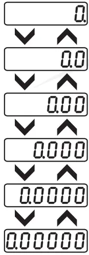 |  | 000000to 0.00000 | This option doesn’t appear if the dot position for scale is at 6th position(LSB position). User can set screen resolution for RUN Mode. & for Set Count. | 0. |
| Lower Display Seln | 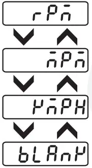 |  | Lower Display Selection:- This parameter will appear only if Preset Type is Selected..RPM:- If selected, Revolution Per Minute(RPM) will display on Lower Display. | RPM | |
| MPM:- If selected, Meter Per Minute(MPM) will display on Lower Display. | |||||
| KMPH:- If selected, Kilo Meter Per Hour(KMPH) will display on Lower Display. | |||||
| Blank:- If selected, Lower Display will be completely off. | |||||
| Leading Zero | 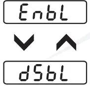 |  | Lead-0:- This parameter allows the user to Enable or Disable Leading Zeros in Run mode.Enable:- If selected Leading Zeros will display in Run mode. | Disable | |
| Disable:- If selected Leading Zeros will not comes in Run mode. | |||||
| User Lock |  |  | Default User Lock Code is “15″ to access Control & Configuration List.User has a choice to set its own User Lock Code between 1 to 9999, this is to prevent unauthorized access of Configuration List. | 15 | |
Mfgd by: Innovative Instruments & Controls LLP
338, New Sonal Link Service Industrial Premises Co-op Society Ltd,
Building No.2, Link Road, Malad (W), Mumbai – 400064.
Tel: 022-66939916/17/18;
E-mail : [email protected]
Website : www.itherm.co.in