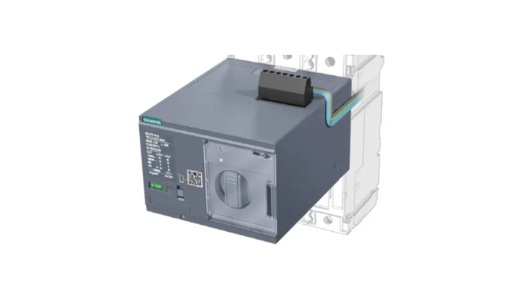
![]() 3VA9137-0HA10 Motor Operator
3VA9137-0HA10 Motor Operator
Instruction Manual
3VA9137 – 0HA.0 3VA9277
0HA.0 3VA9437 – 0HA.0
3VA9447 – 0HA.0
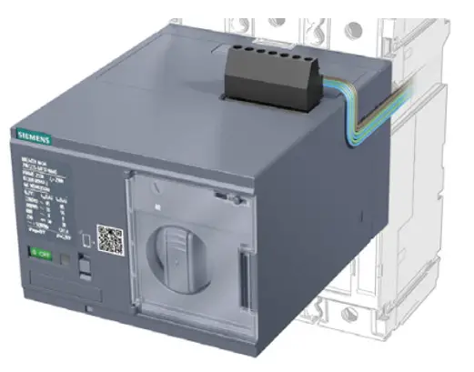
3VA9137-0HA10 Motor Operator

![]() DANGER
DANGER
Hazardous voltage. Will cause death or serious injury. Turn off and lock out all power supplying this device before working on this device.
Replace all covers before power supplying this device is turned on.
Technical Support: Internet: http://www.siemens.com/lowvoltage/technical-support![]() NOTICE
NOTICE
Installation and maintenance must be carried out by qualified personnel.![]() DANGER
DANGER
Hazardous voltage. Will cause death or serious injury. Turn off and lock out all power supplying this device before working on this device. Replace all covers before power supplying this device is turned on.
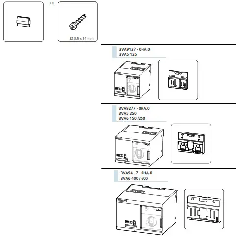
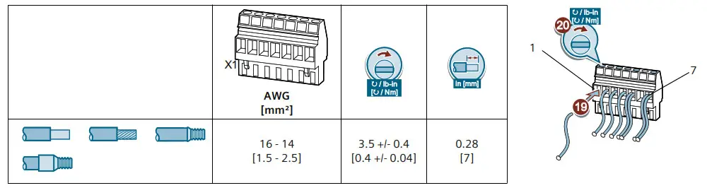
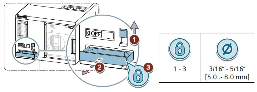
 Required tools

 Content
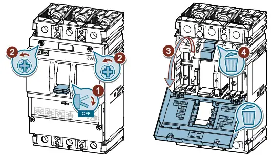
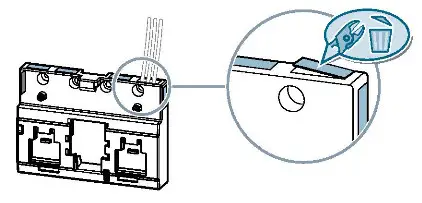
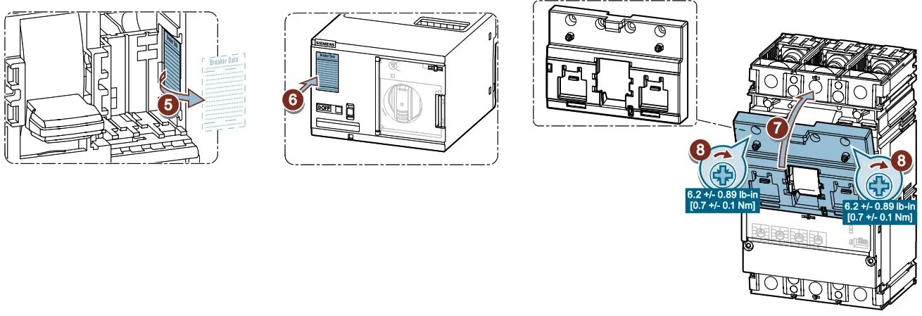
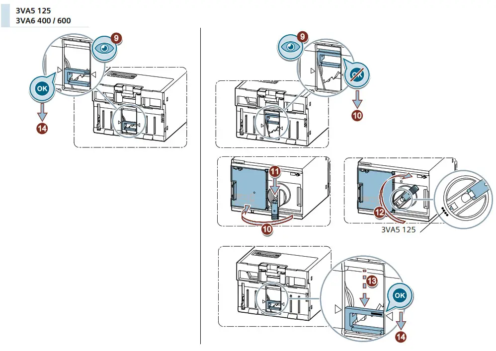
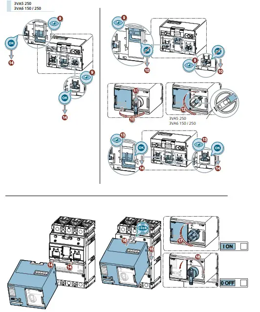
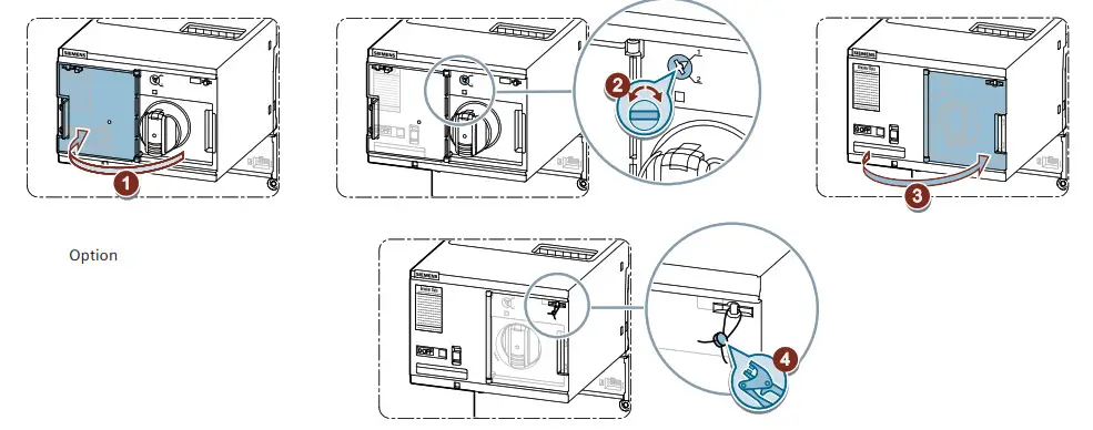
 Assembly
![]() Information
Information
Option
Assembly
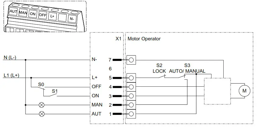
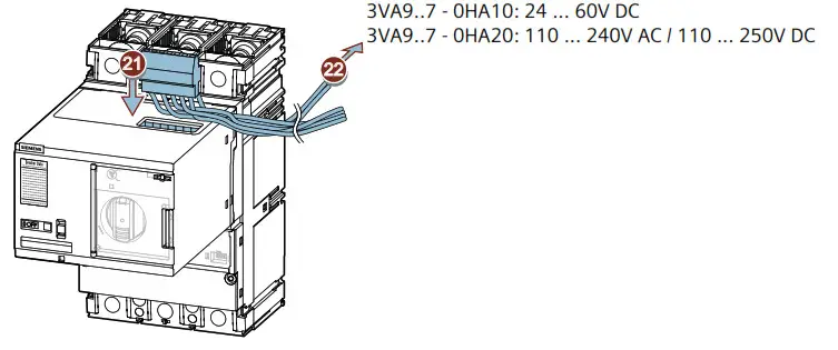
 Connection
Information
Assembly
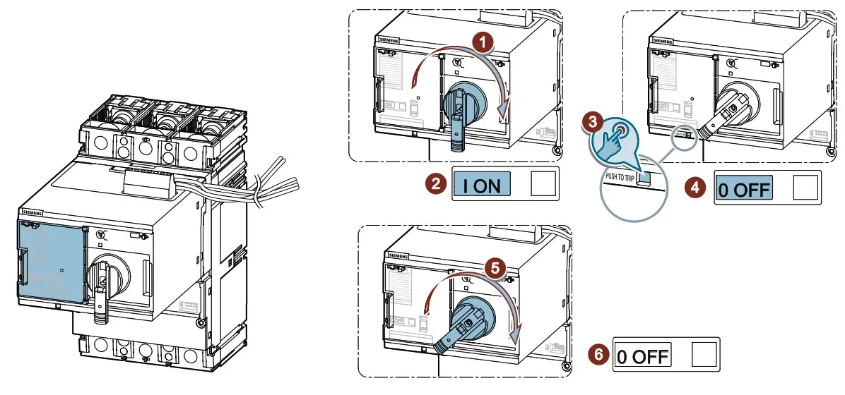
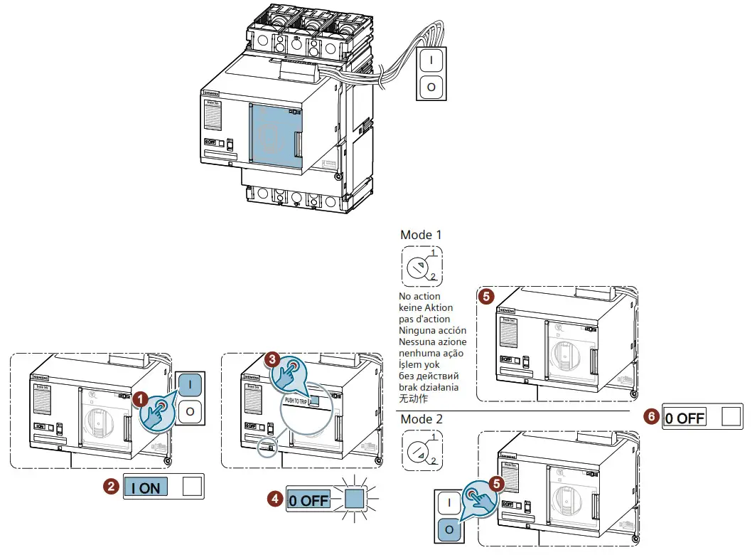
 Settings
| Reset Mode Name] | Switch position | Availability i n Mode | Description |
| MODE 1 Automatic Reset |  |
AUTO | I n “MODE 1” with front flap closed (automatic mode), the MO320 switches the circuit brea- ker automatically from TRIP to OFF. |
| Reset Mode Name] | Switch position | Availability i n Mode | Description |
| MODE 1 Automatic Reset | |
AUTO | I n “MODE 2 ” with front flap closed (automatic mode), the MO320 waits for the cable-based OFF signal to switch the circuit breaker from TRIP to OFF. |
| MODE 1/ MODE Automatic Reset Remote/Manual Reset |
|
MANUAL | I n “MODE 2 ” with front flap closed (automatic mode), the MO320 waits for the cable-based OFF signal to switch the circuit breaker from TRIP to OFF. |
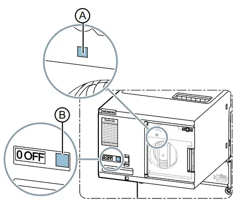
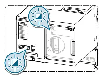
| A | ACT |  |
 |
 |
| Not in operation | Error | In operation |
| B | TRIP | |
| Molded case circuit breaker in TRIP |
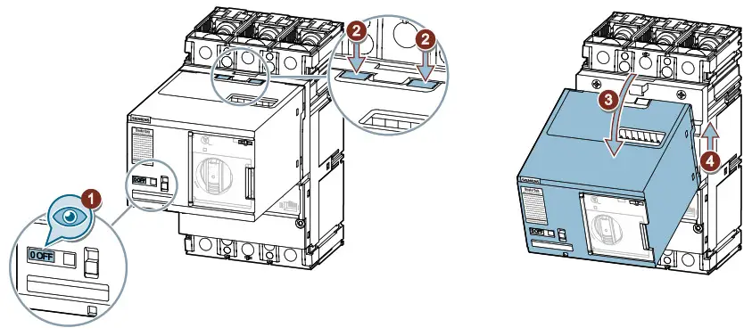
 Replace MO320
Manual
Information
Automatic
Locked
Test
Manual
Automatic
Information
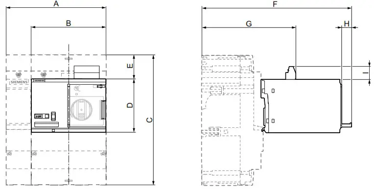
| 3VA5 | 3VA6 | |||
| 125 | 250 | 150 / 250 | 400 / 600 | |
| A | 4.0 in [101.5 mm] |
5.5 in [139.6 mm] |
5.5 in [139.6 mm] |
7.2 in [183.6 mm] |
| B | 3.0 in [76.2 mm] |
4.1 in [104.6 mm] |
4.1 in [104.6 mm] |
5.4 in [137.6 mm] |
| C | 5.1 in [130 mm] |
6.2 in [158 mm] |
7.0 in [178 mm] |
9.7 in [247 mm] |
| D | 2.8 in [70 mm] |
3.0 in [75 mm] |
3.0 in [75 mm] |
3.6 in [92 mm] |
| E | 0.7 in [17.6 mm] |
0.9 in [22.3 mm] |
0.9 in [22.6 mm] |
1.6 in [40.5 mm] |
| F | 7.1 in [181 mm] |
8.0 in [201.4 mm] |
8.6 in [217.9 mm] |
10.1 in [256 mm] |
| G | 4.8 in [121.1 mm] |
5.0 in [126.6 mm] |
5.6 in [143.1 mm] |
6.7 in [170.2 mm] |
| H | 0.6 in [15 mm] |
|||
| I | 0.7 in [17.2 mm] |
|||
NOTICE
These instructions do not purport to cover all details or variations in equipment, or to provide for every possible contingency i n connection with installation, operation, or maintenance. Should additional information be desired, please contact the local Siemens sales office. The contents of this instruction manual shall not become part of or modify any prior o r existing agreement, commitment, or relationship. The sales contract contains the entire obligation of Siemens. The warranty contained in the contract between the parties is the sole warranty o f Siemens. Any statements contained herein do not create new warranties o r modify the existing warranty.
Trademarks – Unless otherwise noted, all names identified b y ® are registered trademarks o f Siemens AG o r Siemens Industry, Inc. The remaining trademarks i n this publication may be trademarks whose use by third parties for their own purposes could violate the rights of the owner.
![]() © Siemens AG 2016
© Siemens AG 2016
Subject to change without prior notice. Store for use at a later date.
Technische Änderungen vorbehalten. Zum spadteren Gebrauch aufbewahren.
A5E03472775204-03
3ZW1012-1VA01-8AA0


