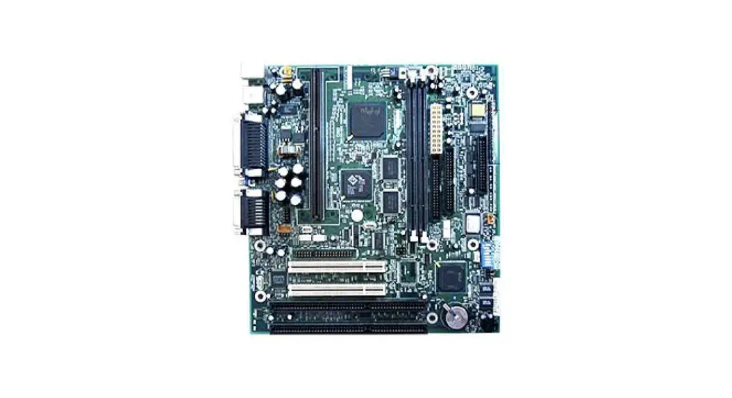
![]() COMO Mainboard
COMO Mainboard
User Guide
COMO Mainboard
COMO
| Device Type | Mainboard |
| Processor | Pentium II/Celeron |
| Processor Speed | 233/266/300/333MHz |
| Chip Set | Intel 440EX |
| Video Chip Set | ATI |
| Maximum Onboard Memory | 256MB (EDO & SDRAM supported) |
| Maximum Video Memory | 1MB |
| Audio Chip Set | Unidentified |
| Cache | 0/128/256/512KB (located on the CPU) |
| BIOS | Unidentified |
| Dimensions | 243mm x 223mm |
| I/O Options | 32-bit PCI slots (2), floppy drive interface, game/MIDI port, green PC connector, IDE interfaces (2), parallel port, PS/2 mouse port, serial ports (2), VGA port, IR connector, USB connectors (2), ATX power connector, line in, line out, audio in – CD-ROMs (2), SB-link connector, wake on LAN connector, wake on modem connector |
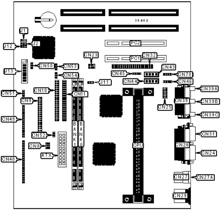
CONNECTIONS
| Purpose | Location | Purpose | Location |
| ATX power connector | ATX | Video sound connector | CN45 |
| Power fan power | CN8 | Modem connector | CN46 |
| Floppy drive interface | CN9 | Power LED | CN48/pins 1 – 3 |
| IDE interface 1 | CN10 | IDE interface LED | CN48/pins 5 – 7 |
| IDE interface 2 | CN11 | Soft off power supply | CN48/pins 8 – 10 |
| SB-link connector | CN23 | IR connector | CN48/pins 11 – 17 |
| Serial port 1 | CN24 | Speaker | CN48/pins 19 – 22 |
| Serial port 2 | CN25 | Keylock | CN49/pins 1 – 3 |
| Parallel port | CN26 | Reset switch | CN49/pins 4 & 5 |
| USB connector 1 | CN27 | Green PC connector | CN49/pins 7 & 8 |
| USB connector 2 | CN27A | LAN LED | CN49/pins 10 – 12 |
| PS/2 mouse port | CN29 | SM bus connector | CN49/pins 14 – 16 |
| VGA port | CN31 | Wake on LAN connector | CN50 |
| AMC connector | CN32 | Wake on modem connector | CN51 |
| Game/MIDI port | CN39 | Chassis intrusion connector | CN52 |
| Microphone in | CN39A | CPU fan power | CN53 |
| Line in | CN39B | Chassis fan power | CN54 |
| Line out | CN39C | Modem connector | CN70 |
| Audio in – CD-ROM | CN43 | 32-bit PCI slots | PC1 – PC2 |
| Audio in – CD-ROM | CN44 |
USER CONFIGURABLE SETTINGS
| Function | Label | Position | |
| » | Factory configured – do not alter | J1 | Unidentified |
| » | Factory configured – do not alter | J2 | Unidentified |
| » | On board AGP enabled | J11 | Pins 2 & 3 closed |
| On board AGP disabled | J11 | Pins 1 & 2 closed | |
| » | Floppy drive enabled | J12 | Pins 2 & 3 closed |
| IR enabled | J12 | Pins 1 & 2 closed | |
| » | CMOS memory normal operation | J13/5 | On |
| CMOS memory clear | J13/5 | Off | |
| » | Password enabled | J13/6 | On |
| Password disabled | J13/6 | Off | |
| » | CMOS setup enabled | J13/7 | On |
| CMOS setup disabled | J13/7 | Off | |
| » | Floppy drive write protect disabled | J13/8 | On |
| Floppy drive write protect enabled | J13/8 | Off | |
DIMM CONFIGURATION
| Size | Bank 0 | Bank 1 |
| 8MB | (1) 1M x 64 | None |
| 16MB | (1) 2M x 64 | None |
| 16MB | (1) 1M x 64 | (1) 1M x 64 |
| 24MB | (1) 2M x 64 | (1) 1M x 64 |
| 32MB | (1) 4M x 64 | None |
| 32MB | (1) 2M x 64 | (1) 2M x 64 |
| 40MB | (1) 4M x 64 | (1) 1M x 64 |
| 48MB | (1) 4M x 64 | (1) 2M x 64 |
| 64MB | (1) 8M x 64 | None |
| 64MB | (1) 4M x 64 | (1) 4M x 64 |
| 72MB | (1) 8M x 64 | (1) 1M x 64 |
| 80MB | (1) 8M x 64 | (1) 2M x 64 |
| 96MB | (1) 8M x 64 | (1) 4M x 64 |
| 128MB | (1) 16M x 64 | None |
| 128MB | (1) 8M x 64 | (1) 8M x 64 |
| 136MB | (1) 16M x 64 | (1) 1M x 64 |
| 144MB | (1) 16M x 64 | (1) 2M x 64 |
| 160MB | (1) 16M x 64 | (1) 4M x 64 |
| 192MB | (1) 16M x 64 | (1) 8M x 64 |
| 256MB | (1) 16M x 64 | (1) 16M x 64 |
| Note: Board accepts EDO & SDRAM memory. | ||
CACHE CONFIGURATION
Note: 256KB/512KB cache is located on the Pentium II CPU. 128KB cache is located on the Celeron 300A & 333 CPU.
VIDEO MEMORY CONFIGURATION
Note: Video memory is factory installed and is not configurable.
CPU SPEED SELECTION
| CPU speed | Clock speed | Multiplier | J13/1 | J13/2 | J13/3 | J13/4 |
| 233MHz | 66MHz | 3.5x | On | Off | Off | On |
| 266MHz | 66MHz | 4x | Off | On | On | On |
| 300MHz | 66MHz | 4.5x | Off | On | Off | On |
| 333MHz | 66MHz | 5x | Off | Off | On | On |
TRIGEM MICROSYSTEMS, INC.


