TYROLIT DME38UW, DME33MW Drill Motor Instruction Manual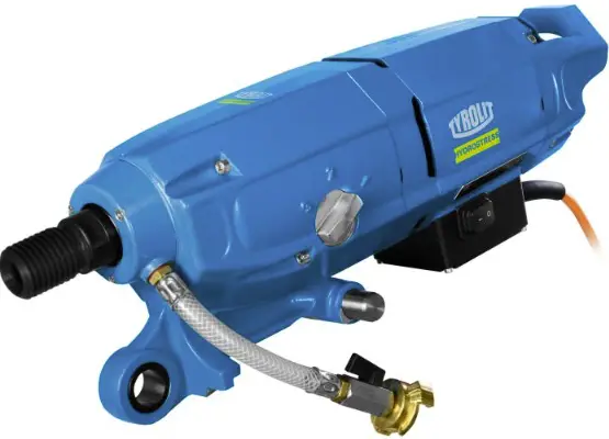
Introduction
Congratulations!
With a Hydro stress unit from TYROLIT you have chosen a tried and tested piece of equipment designed and built to the highest technical standards. Only genuine TYROLIT Hydro stress replacement parts can guarantee quality and interchangeability. If maintenance work is neglected or carried out inexpertly we will be unable to honor our warranty obligations. Any repair work must be carried out by trained personnel only.
Our after-sales service is available to help ensure that your TYROLIT Hydro stress units remain in perfect working order.
We hope that working with your TYROLIT unit will be a satisfying and fault-free experience.
TYROLIT Hydro stress
Concerning these instructions
![]() These instructions are just one part of the documentation which is supplied together with the electric tool.
These instructions are just one part of the documentation which is supplied together with the electric tool.
These instructions go together with the “Core Drills Safety Manual / System Description” to form a complete set of documentation.
These instructions, together with the “Core Drills Safety Manual / System Description”, are a constituent of the equipment. They describe how to use the equipment safely and properly in all phases of operation.
- Read the instructions carefully before use, particularly the safety instructions.
- Keep the instructions for the entire service life of the equipment.
- Ensure that the instructions are available to the operator and the service engineers at all times.
- Pass the instructions on to all subsequent owners or users of the equipment.
- Update instructions with all supplements received from the manufacturer.
Symbols in these instructions
![]() DANGER
DANGER
Warning of danger, where failure to comply could lead to death or serious injury.
![]() WARNING
WARNING
Warning of danger, where failure to comply could lead to injuries or damage to property.
![]() WARNING
WARNING
Warning – dangerous electrical voltage.
Before working in an area identified in this way, the installation or device must be fully disconnected from the power (voltage) and secured against being accidentally powered up again.
![]() INFORMATION
INFORMATION
Information for optimum use of equipment. Failure to take note of this information may mean that the performance information shown in the technical data can no longer be guaranteed.
![]() RECYCLING
RECYCLING
Take waste for recycling.
![]() DISPOSAL
DISPOSAL
The normal national and regional rules and guidelines must be observed during disposal.
Safety
Core drilling systems may only be operated by authorised persons. Information about authorised persons can be found in the “Core Drills Safety Manual / System Description”.
Protective devices and signs on the equipment
Protective devices
Protective devices may only be removed if the equipment has been switched off, disconnected from the mains and is at a standstill. Safety components in particular should only be removed and refitted by authorised personnel.
Before switching the equipment back on again, check that the safety elements are operating correctly.
Signs on the equipment
Safety sign
- Wear safety shoes

- Wear gloves
- Wear a breathing mask
- Wear a helmet, goggles and hearing protection
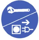
- Read the instructions
- Before working on the equipment unplug mains


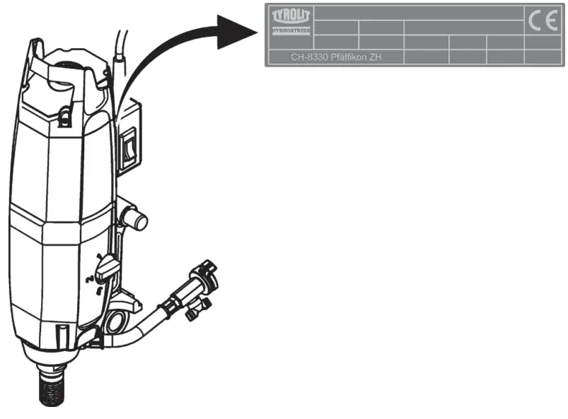
Name plate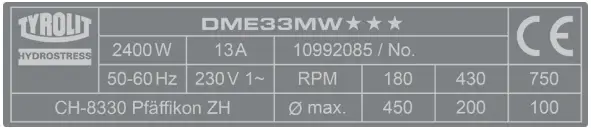
Safety clothing
Anyone working with and on core drilling systems is strictly required to wear individual protective equipment.
| Safety clothing | |||
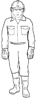 |  |  |  |
 |  |  | |
Spare parts and modifications
Only original spare parts from TYROLIT Hydro stress must be used.
Otherwise damage may be caused to the equipment or to other property and persons.
No additions or modifications must be made to the equipment without written permission from TYROLIT Hydro stress.
Danger and working area
Danger zone at electrical tool
The marked area on the drawing defines the danger zone of the electrical and cutting tool.
The minimum clearance of 15 cm must be maintained during operation.
Danger zone at electrical tool.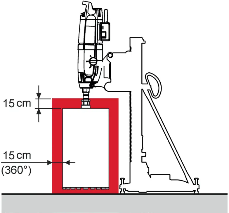
Danger zone at workplace
![]() Information about the danger zone at the workplace can be found in the “Core Drills Safety Manual / System Manual”.
Information about the danger zone at the workplace can be found in the “Core Drills Safety Manual / System Manual”.
Product-specific dangers
Personal protection device (RCD, PRDC, GFCI) Only ever work if a serviceable current-operated personal protection device is present (PRCD, GFCI).
Personal protection device.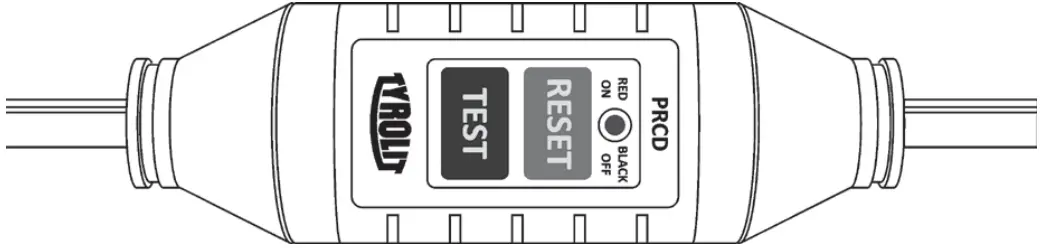
DANGER
Failure to comply will result in a risk of death or serious injuries
- Keep your electrical tool away from rain and moisture. Water penetrating an electrical tool increases the risk of electric shocks.
- It is not allowed to work without current-operated personal protection device.
Overhead drilling
- Overhead drilling is not permitted in wet conditions.
Residual risks
Risk of serious injuries from the residual risks described in the chapters that follow.
Diamond segments flying off
- Do not start drilling if any other persons are in the danger zone.
- Ensure that a safety distance is maintained.
- Replace the diamond drill bit is diamond segments start to break off.
Uncontrolled movements and vibration
- Never connect or disconnect cables during operation..
Catching and winding in
Items of clothing or long hair can be caught by the rotating cutting tool.
- Do not wear loose items of clothing at work.
- Wear a hair net if you have long hair.
Damaging vapors and aerosols
Inhaling damaging vapors and/or aerosols can cause breathing problems.
Breathing in the water fog that is created is a health hazard.
- Wear a breathing mask.
- Provide adequate ventilation in confined spaces.
Physical condition
- Do not work whilst under the influence of alcohol, drugs or medication.
- Do not work when you are overtired.
Cutting tool quality
- Do not use damaged cutting tools.
- Check cutting tool for damage before installation.
Risk of cutting tool restart in the event of an accident
- Ensure that the electrical equipment can be stopped quickly.
![]() DANGER
DANGER
Failure to comply with the safety instructions in the “Safety Manual / System Manual” may result in serious injury or even death.
- Please ensure that the “Core Drills Safety Manual / System Description” has been read and understood in full.
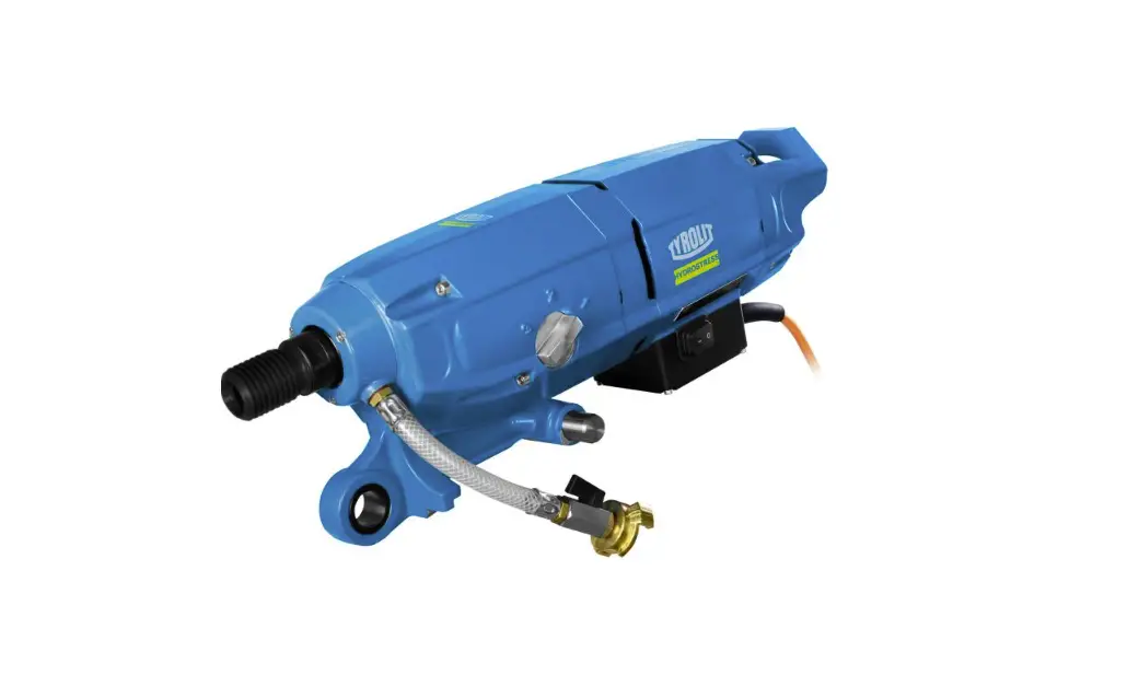
Product description
Core drilling system
- Electrical tool
- Cutting tool
- Drill rig
- Fastening elements

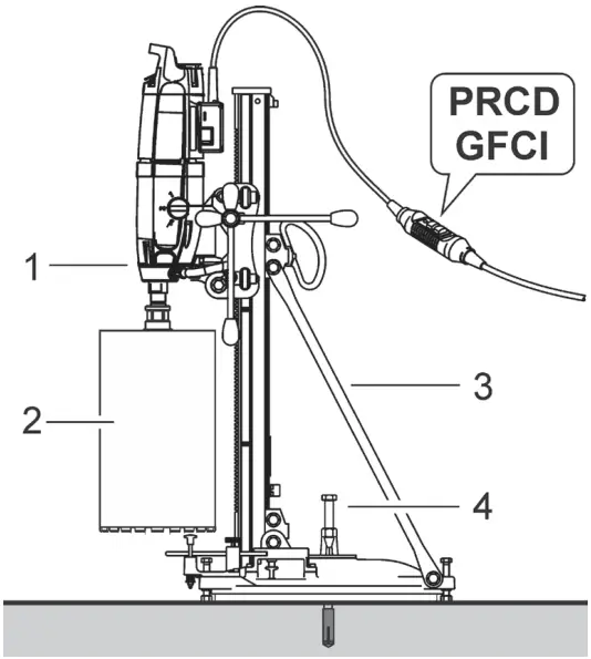
Core drilling system
This electrical tool forms a core drilling system in conjunction with suitable TYROLIT Hydro stress components
Use for correct purpose
The DME33MW and DME33UW electrical tools are intended for stand-controlled wet drilling into mineral subsurface using diamond drill bits no manual operation).
During operation a suitable drilling stand must be used and sufficient anchoring to the subsurface provided using dowels, a vacuum plate or a quick clamping support..
Manipulation or modifications to the equipment, the drilling stand or the accessories are not permitted. Always use original TYROLIT Hydro stress accessories and suitable tools during use in order to prevent injuries.
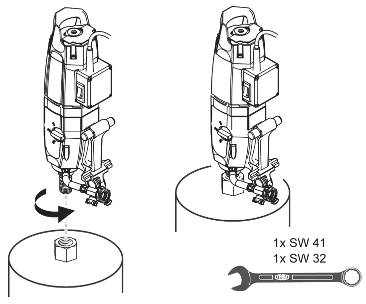
Scope of supply
- Drill motor
- WAF32 / WAF22 tool wrenches
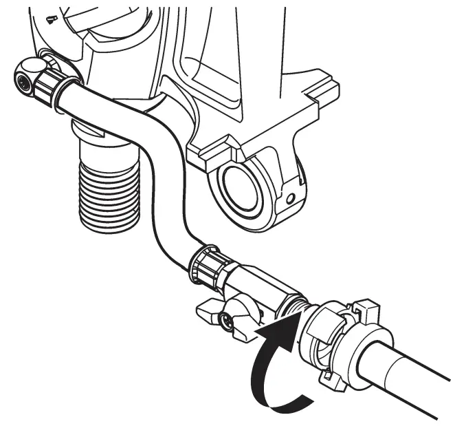
- Water line adapter
Technical data and main dimensions
Technical data
| Drill motor | DME33MW««« | DME33UW««« | ||
| Nominal voltage | 230 V | 110 V | 230 V | 110 V |
| Frequency | 50 Hz | 60 Hz | 50 Hz | 60 Hz |
| Drill diameter range | 50 – 450 mm | |||
| Nominal power | 3.3 kW | 2.7 kW | 3.3 kW * | 2.7 kW |
| Nominal current | 15.9 A | 25 A | 15.9 A * | 25 A |
| On-load speed | 180/430/750 1/min | |||
| Idle speed | 360/820/1240 1/min | |||
| Engine cooling | Air | |||
| Tool fitting (external) | 1¼“ UNC | |||
| Operation | drill rig-controlled | |||
| Application | wet | |||
| Electronic overload protection | Yes | |||
| Mechanical overload protection | Yes | |||
| PRCD protective switch | Yes | |||
| Power display | Yes | |||
| Service indicator | Yes | |||
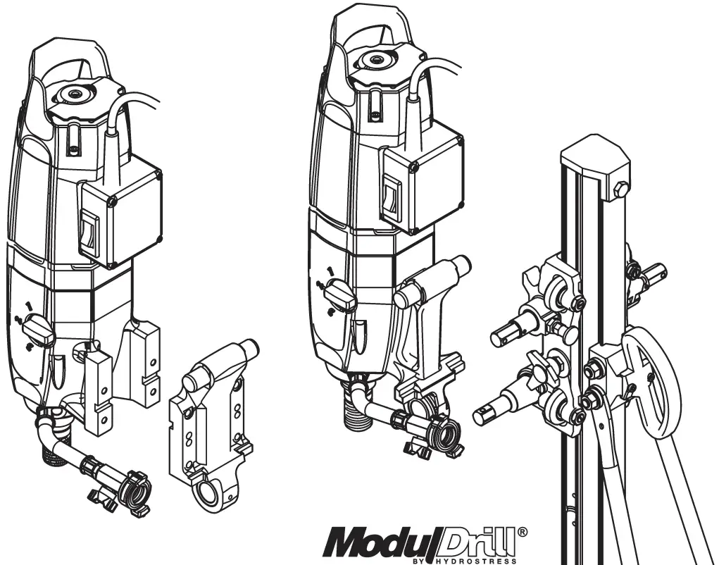
| Drill stand holder | Modul Drill TM | Universal plate | ||
| Weight | 13.7 kg | 13.6 kg | ||
* Australian version: 3.1 kW / 15 A
Noise emission
| Noise data according to ISO 3744 | |
| Parameter | Value |
| Sound pressure level L pA | 86.1 dB (A) * |
| Maximum sound pressure level L peak | 103.8 dB (A) |
| Sound power level LWA | 105.1 dB (A) * |
Conditions for the measurement:
* Without cutting tool Ø200 mm in operation
Measurements
Measurements in mm.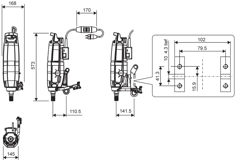
Lubricants, fluids
| Lubricants, fluids and sealants | |
| Parameter | Value |
| Gear oil | ISO 100 (TYROLIT No. 10993829/500ml) |
Name plate
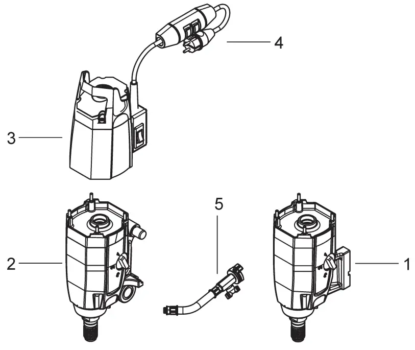
Design and function
Design
- Gearbox DME33UW
- Gearbox DME33MW
- Motor
- Residual current circuit breaker
- Water connection

Function
Functional description
The drilling spindle of the electrical tool is powered by an electric motor via a mechanical manual gearbox. The optimum speed of the cutting tool is set using the gears of the gearbox.
The electric motor is air-cooled.
Working with the electrical tool is protected by a current-operated personal protection device (PRDC, GFCI).
Operating elements and displays
Operating elements
- Handle
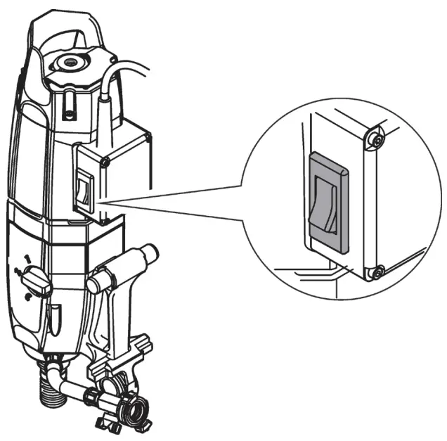
- Main On / Off switch
- Rotary switch / gear
- Water valve
Controls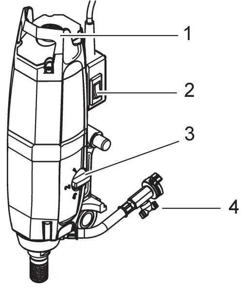
Displays (230 V version)
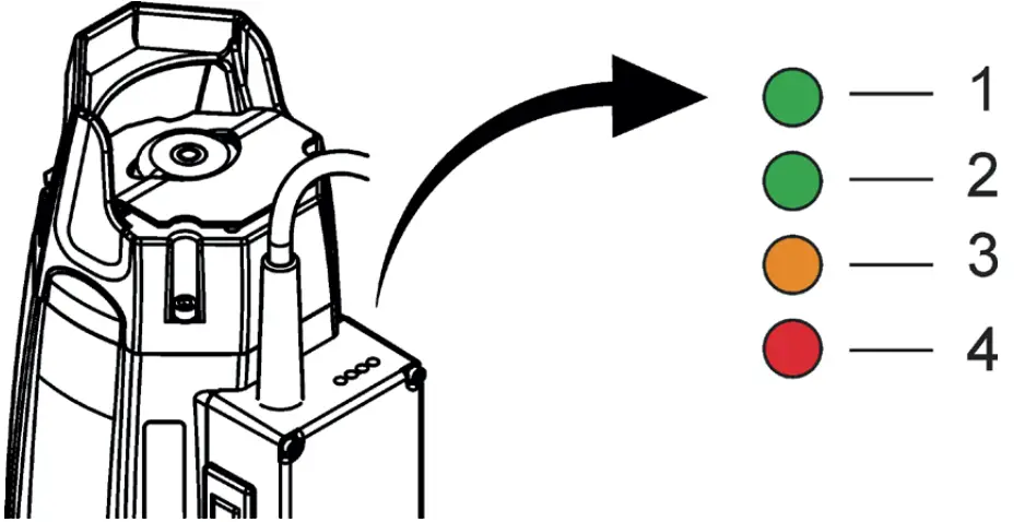
| Power display when at standstill | |
| LED 1 illuminates in green | Electrical tool is ready |
| LED 3 flashes in orange | Electrical tool requires service |
| Power display during operation | |
| LED 1/2 illuminates in green | Motor operating in optimum power range |
| LED 3 illuminates in orange | Motor operating at power limit |
| LED 4 illuminates in red | Motor running at overload and will shut off after 3 seconds |
Assembly / Disassembly
Drill rig interface
Cutting tool interface
Power supply
![]() INFORMATION
INFORMATION
- The power supply must correspond with the information on the type plate.
- Protect the connecting cables from heat, oil and sharp edges.
- Do not use connecting cables for unsuitable purposes.
- Never carry the electrical tool using the connecting cable.
- Do not use the connecting cable to pull the plug out of the socket.
- In the event of power failure: switch of electrical tool, pull out the plug.
![]() Extension cable
Extension cable
- Only use approved and appropriately marked extension cables outdoors.
- Extension cables with multiple sockets and simultaneous use of multiple devices must be avoided.
Always use an extension cable that is approved for the usage area with a sufficient cross-section.
Do not use an extension cable with a conductor cross section of 1.25mm² and 16 AWG.
| Recommended minimum cross-sections and maximum cable lengths | |||||
| Cross section mm² | 1,5 | 2,0 | 2,5 | 3,5 | 4,0 |
| 110 V | not permitted | not permitted | not permitted | 20 m | 20 m |
| 220 V-240 V | 20 m | – | 40 m | 50 m | 60 m |
Water connection
Operation
DANGER
- Never work without suitable safety equipment.
- Always wear hearing protection.
- Remove adjusting and installation tools before switching the electrical tool on.
- Never work on ladders.
- Keep children away from the electrical tool and the working area.
- Avoid abnormal postures.
- Ensure that you have firm footing, and keep your balance at all times.
- Avoid body contact with earthed surfaces such as pipes, heaters, ovens and refrigerators.
There is an increased risk of electric shock if your body is earthed.
Settings
Gears
Position the selector switch in accordance with the required drilling diameter.
Never use force to move the switch, and only move it if the electrical device is slowing down or stopped.
Water supply
Ensure that water supply is provided.
Start / switch on electrical tool
- The electrical tool is correctly fitted to the drilling stand.
- The cutting tool is firmly screwed to the electrical tool.
- The electrical tool is correctly attached to the power supply.
- The power supply is monitored by the PRCD residual current circuit breaker.
- The water supply is attached, and the cutting tool is being supplied with water.
- Start motor using the On/Off switch.
Start the electric tool.
Monitoring, checking
Residual current circuit breaker
- Switch on and check PRCD residual current circuit breaker
Checking procedure:
- Plug the electrical tool into a socket with an earth connection.
- Press the Reset button on the PRCD residual current circuit breaker (indicator must illuminate).
- Press the Test button on the PRCD residual current circuit breaker (indicator must go off).
![]() DANGER
DANGER
If the indicator does not go off, the device must not be used. The electrical tool must be repaired by qualified experts using original spare parts.
Press the Reset button on the PRCD residual current circuit breaker (indicator must illuminate).
Residual current circuit breaker.
Malfunctions
| Malfunctions | ||
| Malfunction | Possible cause | Remedy |
| The electrical tool cannot be started | Mains cable is defective |
|
| Faulty power supply |
| |
| Electric motor or electronics faulty |
| |
| Electrical tool starts up and then switches off again | Fuse of building site power supply trips |
|
| Motor running but drill bit not rotating | Gear speed selector |
|
| Defective gears |
| |
| Unable to fit cutting tool | Thread dirty |
|
| Thread defective |
| |
| Water coming out of housing (relief drilling) | Shaft sealing ring defective |
|
| Water coming out of housing (relief drilling) | Shaft sealing ring defective |
|
| No water emerging | Water valve on feed line is closed |
|
| Water line is blocked |
| |
| Defective water valve |
| |
| Insufficient water pressure |
| |
Servicing and maintenance
Unplug the equipment before carrying out maintenance or repair work.
| Servicing and maintenance table | |||||||
| Before each use | At end of work | Weekly | Yearly | After faults | After damage | ||
| Drive motor |
| X | X | X | |||
| Drill bit thread |
| X | |||||
| X | X | X | X | |||
| Drilling spindle |
| X | |||||
| Cables, switches, plug-in devices |
| X | X | X | X | ||
| Water economy |
| X | X | X | |||
| X | ||||||
| Service |
| After service indication (orange LED flashing) (Service interval 150 / 300 / 450 / 600 hours) | |||||
Take waste for recycling
![]()
![]() TYROLIT Hydro stress tools are manufactured using a high proportion of recyclable materials.
TYROLIT Hydro stress tools are manufactured using a high proportion of recyclable materials.
A prerequisite for recycling is proper material separation. In many countries, TYROLIT is already prepared for taking back your used equipment for recycling.
Contact TYROLIT customer service or your sales adviser.
EC Declaration of Conformity
Description: Electric drill motor
Type designation: DME33MW / DME33UW
We declare under our sole responsibility that this product complies with the following directives and standards:
Applied directions
2006/42/EC 17.05.2006
2014/30/EU 26.02.2014
2012/19/EU 04.07.2012
Applied standards
EN ISO 12100: 2010
EN 62841-1: 2015+AC:2015
EN 62841-3-6 : 2014+AC:2015+A11:2017
EN 55014-1: 2017
EN 55014-2: 2015
EN 61000-3-2: 2019
EN 61000-3-3: 2013+A1:2019
Pfäffikon, 07.10.2021
Roland Kägi
Operations + R&D Machines
Customer Support
TYROLIT Hydrostress AG
Witzbergstrasse 18
CH-8330 Pfäffikon
Switzerland
Tel. 0041 (0) 44 952 18 18
Fax 0041 (0) 44 952 18 00