![]()
ThermoGroup
Magnify Thermal Camera for Fever Detection
Operation Guide
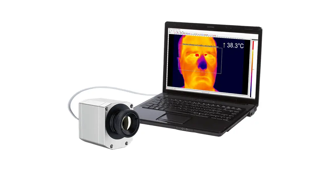
Connecting thermal camera
Supply the thermal camera with 12V DC power. Connect the thermal camera directly to the user’s computer using an Ethernet cable. Multiple thermal cameras can be connected using a router or network switch.
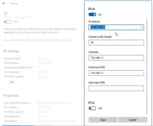
IP Configuration of the computer
If the thermal camera is directly connected to the computer, manually set the computer’s IP address to be 192.168.1.X (X can be any number between 1 and 254). If multiple thermal cameras are connected to the computer via a router, set IP address assignment to be automatic. Run ThermoGroup after setting the computer’s IP address.
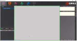
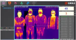
Playing thermal image
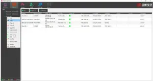
When a thermal camera is directly connected to a computer, ThermoGroup will automatically add the device to the left panel. Right-click the device name and select “Preview” to display the thermal image. If multiple cameras are connected via a router, click “Add All” under the “Device” menu, right-click the product list in the left panel, select “Play All”, and click “Preview” to display infrared images.
Manually turn the camera lens to focus until the image is sharp and clear. 15 minute warm-up of the camera is needed for accurate temperature measurement. Try to avoid high-temperature objects in the background.
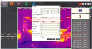
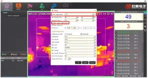
Selecting temperature measurement mode temperature measure
There are two measurement Innerbody temperature modes. C measurement modes in the software, Forehead and temperature modes. Click “Human Body” to choose from. Forehead and
Forehead mode: This mode is for sophisticated users only. The thermal camera shows the real surface temperature of the forehead, which is affected by ambient temperature and usually between 31°C and 35°C. A simple way to reflect the body temperature is to compensate for the difference between surface temperature and body temperature. To do that, input a value in “Compensate”, eg. 2. In this case, the shown temperature will be 2°C higher than the real measured temperature. The users may change the “Compensate” value as ambient temperature changes.
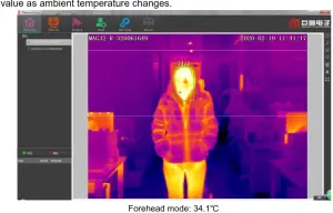
Inner body mode: The thermal imager automatically converts the measured forehead surface temperature into body temperature using a special algorithm. This mode is recommended for most users.
“Low thresh” and “High thresh” specify the temperature range in which an object is identified as a human. A rectangle will then be drawn and the highest temperature within will be read as the person’s temperature. Increase “Low thresh” value if the camera can’t identify a human, decrease “low thresh” if there are too many false identifications.
Please do not adjust the other parameters unless by the guidance of a professional.
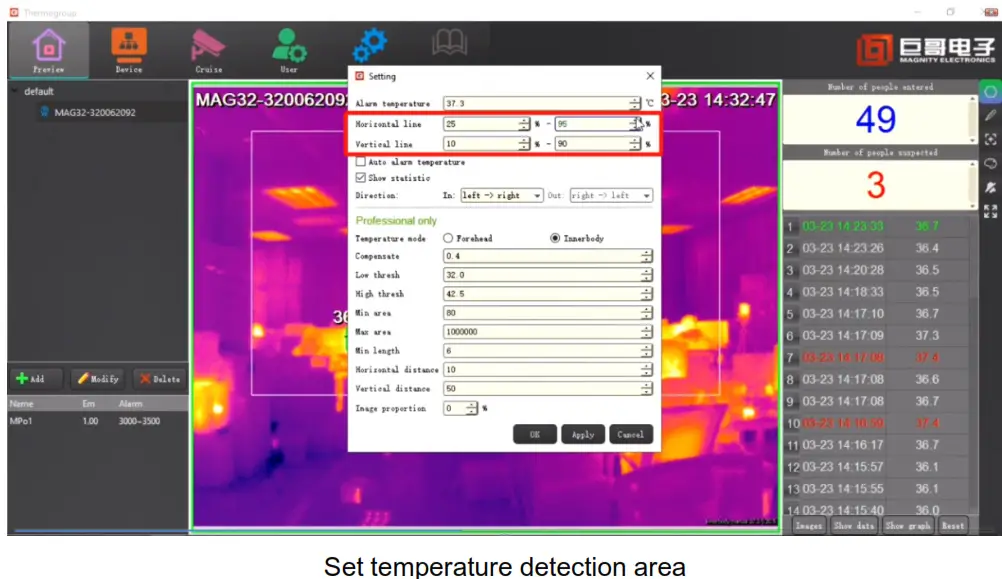
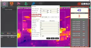
The setting temperature measurement area
In order to avoid false alarms due to high-temperature sources other than humans, a temperature measurement area is set by horizontal and vertical detection lines. High temperatures outside the detection area will not trigger the alarm.
Setting alarm threshold
The alarm temperature can be manually set, eg. 37.3°C. The user can also select “Auto alarm temperature”. In this case, the camera uses recently measured normal persons’ average temperature as a baseline. An alarm will be triggered when a person’s temperature is clearly above the average.
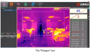
Avoiding interference in the measurement area
High-temperature interference inside the temperature measurement area can be shielded by the “Polygon” tool. Left-click to select the area to be shielded,drag the mouse the draw, and right-click to end. It is recommended that the background be as clean as possible.
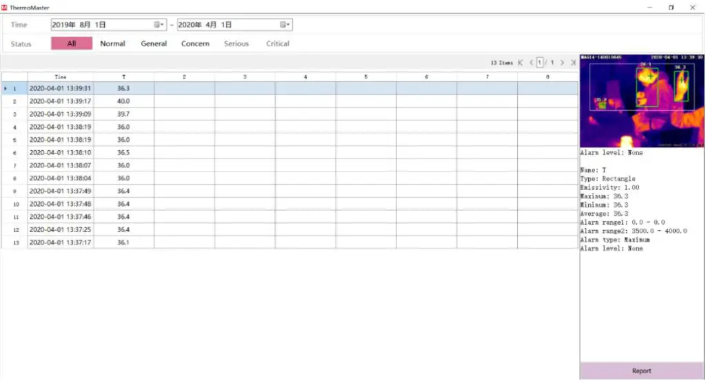
Statistics
Check “Show statistic” to display in the right panel the number of measurements in the day, number of abnormal temperature readings, and the results of all measurements. The statistics panel will be automatically reset at 0 am mid-night each day.
Click “Show data” to review the history of statistics every day.
Connecting external alarm devices go off.
When the measured human temperature exceeds the threshold and the alarm is triggered, the thermal camera will send a signal to the external alarm device. The signal will remain until the alarm goes off.
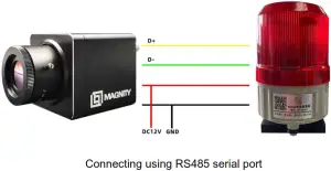
There are two ways to connect an external alarm device to the thermal camera depending on the type of the external alarm device. The first method is to connect the alarm device to the serial port of the thermal camera, as shown below if the alarm device can be controlled by RS485.
Click “IO&Port” in “Parameters” under the “Setting”menu,set “Baudrate” 9600.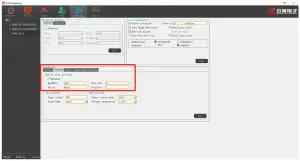 The second method is to connect the alarm device to the output of the thermal camera. An example is shown below. The amplifier is optional if the relay can be driven by 3.3V (which is the output voltage from OUT when alarm is triggered), while the relay is optional if the alarm device can be driven directly by the amplifier.
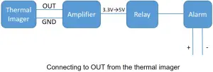
Connecting TV
After being configured using ThermoGroup, the thermal camera can work without a PC. Connect the thermal camera Video out to a TV using a video cable infrared images will be displayed on the TV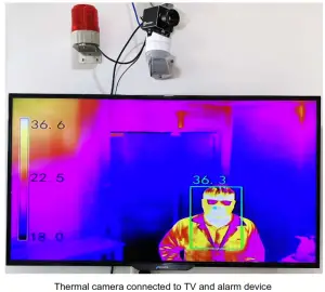
![]() SHANGHAI MAGNIFY ELECTRONICS CO., LTD.
SHANGHAI MAGNIFY ELECTRONICS CO., LTD.


