SKYDANCE ES32 PIR Sensor Stair Light Controller
Features
- Multiple function PIR sensor stair light controller with daylight sensor.
- 32 channels constant voltage output drive low voltage LED strip, Max. 1A current per channel.
- 2 groups SPI(TTL) signal output, drive 27 kinds IC digital RGB LED strip, IC type and R/G/B order can be set. Compatible ICs: TM1803, TM1804, TM1809, TM1812, UCS1903, UCS1909, UCS1912, UCS2903,
UCS2909, UCS2912, WS2811,WS2812, TM1829, TM1914A, GW6205, GS8206,GS8208,LPD6803, LPD1101, D705, UCS6909, UCS6912, LPD8803, LPD8806, WS2801, WS2803, P9813, SK9822. - Easy operation with OLED display and 3 buttons.
- four work light mode selectable.
- Two stair light controller can cascade.
- Built-in multiple color mode, speed 1-8 grade adjustable.
- Push switch can also be as induction signal input.
- With fast self-testing function.
Technical Parameters
| Input and Output | |
| Input voltage | 5-24VDC |
| Output voltage | 32 x (5-24)VDC |
| Output current | 32CH,1A/CH |
| Output power | 32 x (5-24)W |
| Output type | Constant voltage + SPI(TTL) |
| Environment | |
| Operation temperature | Ta: -30 OC ~ +55 OC |
| Case temperature (Max.) | T c: +85OC |
| IP rating | IP20 |
| Warranty and Protection | |
| Warranty | 5 years |
| Protection | Reverse polarity |
| Safety and EMC | |
| EMC standard (EMC) | EN55032:2015, EN61000-3-2:2014, EN61000-3-2:2013, EN55024 :2010/A1:2015 |
| Safety standard(LVD) | EN 61347-1:2015 EN 61347-2-11:2015 |
| Certification | CE,EMC,LVD |
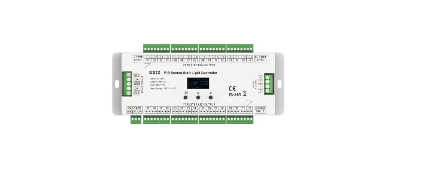
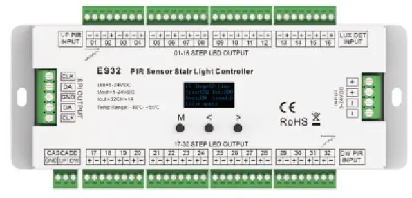
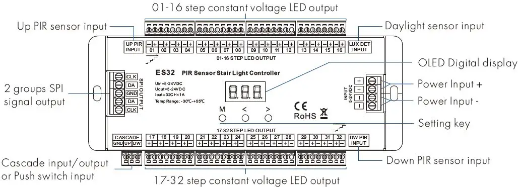
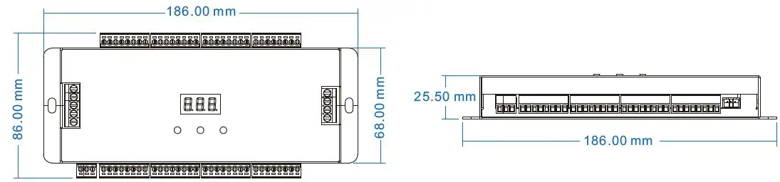
Mechanical Structures and Installations
Accessories
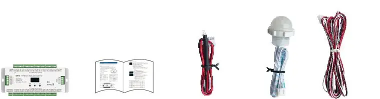
- LED Controller 1 pcs
- User Manual 1 pcs
- Daylight sensor(30cm)1 pcs
- PIR sensor 2 pcs.
Wiring Diagram
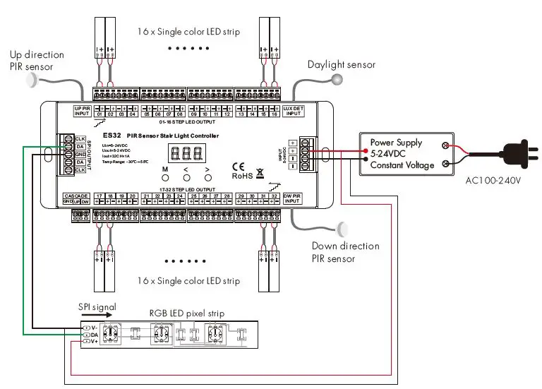
Note: The LED pixel strip also use a separate power supply.
OLED screen and key operation
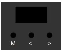
- Short press M key, enter current work light mode parameter setting state.
- Long press M key for 2s, enter system parameter setting state, to switch four work light mode, set light off mode, set push switch input function, set chip type and RGB order, set daylight sensor threshold.
- When in parameter setting state, short press M key to switch between multiple parameter item, press < or > key for parameter adjustment.
- Long press M key or wait 15s to quit parameter setting state.
- Long press M & > key for 2s, start-up direction induction light testing.
- Long press M & < key for 2s, start down direction induction light testing.
- Long press < & > key for 2s, restore factory default parameter.
- The fourth line display color mode name default, and will display induction signal input indication or light on/off state.
- When induction light control process is over, the light will turn off after 10s(@speed 8) automatically. For speed 1-8 level, the turn-off delay time is 45/40/35/30/25/20/15/10s respectively.
System parameter setting

- WorkMode: Switch between four work light modes.
- CV_Step: Only multiple constant voltages LED strip light mode.
- SD_Line: Only 1 or 2 straight line digital pixel LED strip light mode.
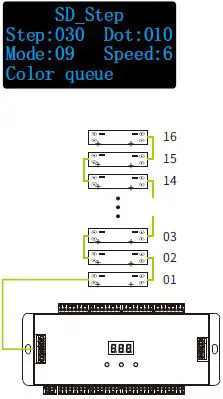
- SD_Step: Only multiple Z-shape digital pixels LED strip light mode.
- CV+SD_L: Multiple constant voltages LED strip + 1 or 2 straight line digital pixel LED strip light mode.
- Off: Switch between two light turn off mode when induction light control process is over.
- Delay sync: The light turn off at the same time after the delay time.
- One by one: The light turn off one by one from the tail end.
- Push: Switch between two push switch functions.
- Cascade: The push switch input work as cascade input/output or simulate PIR inductive input.
- Light on: The push operation will turn on all light and turn off automatically after the delay time.
- Chip: Switch between 10 class chip (below table) and 6 kinds RGB order (RGB,RBG,GRB,GBR ,BRG,BGR). This parameter is valid only for the work mode with SPI signal output.
- DefRGB: RGB hex value for user-define color. The parameter is valid only for the work mode with SPI signal output.
- LuxSet: Daylight sensor threshold or disable (10, 30, 50, 100, 150, 200lux,OFF), With sufficient ambient light, the PIR sensor does not turn on the light. The digital value after * is current detected LUX value.
Digital pixel RGB LED strip compatible IC type list:
| No. | IC type | Output signal |
| 1 | TM1809,TM1804,TM1812,UCS1903,UCS1909,UCS1912, UCS2903,UCS2909,UCS2912,WS2811,WS2812 | DATA |
| 2 | TM1829 | DATA |
| 3 | TM1914A | DATA |
| 4 | GW6205 | DATA |
| 5 | GS8206,GS8208 | DATA |
| 6 | LPD6803,LPD1101,D705,UCS6909,UCS6912 | DATA,CLK |
| 7 | LPD8803,LPD8806 | DATA,CLK |
| 8 | WS2801,WS2803 | DATA,CLK |
| 9 | P9813 | DATA,CLK |
| 10 | SK9822 | DATA,CLK |
Constant voltage LED strip light mode
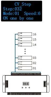
- Step: Total step number, 008-032
- Mode: White mode number, 01-03
- Speed: Speed grade, 1-8, 8 is the fastest speed.
White mode list:
| No. | Name |
| 01 | ON one by one |
| 02 | All OFF,Five ON |
| 03 | All ON,one OFF |
Straight line digital pixel LED strip light mode
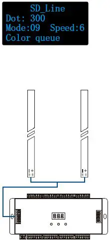
- Dot: Pixel dot number, 032-960
- Mode: Color mode number, 01-12
- Speed: Speed grade, 1-8, 8 is the fastest speed.
Color mode list:
| No. | Name |
| 01 | Red |
| 02 | Orange |
| 03 | Yellow |
| 04 | Green |
| 05 | Cyan |
| 06 | Blue |
| 07 | Purple |
| 08 | White |
| 09 | Color queue ( 7 color + White) |
| 10 | Color chase( 7 color + White) |
| 11 | Color fade (6 color flow) |
| 12 | Rxxx Gxxx Bxxx (User define) |
Constant voltage LED strip + Straight line digital pixel LED strip light mode
- Step: Total step number, 008-032
- Dot: Pixel dot number, 032-960
- Mode: Color mode number, 01-12
- The mode number is used for straight-line digital pixel LED strip only.
- The mode for constant voltage LED strip is fixed On one by one.
- Speed: Speed grade, 1-8, 8 is the fastest speed.
Color mode list:
| No. | Name |
| 01 | Red |
| 02 | Orange |
| 03 | Yellow |
| 04 | Green |
| 05 | Cyan |
| 06 | Blue |
| 07 | Purple |
| 08 | White |
| 09 | Color queue ( 7 color + White) |
| 10 | Color chase ( 7 color + White) |
| 11 | Color fade (6 color flow) |
| 12 | Rxxx Gxxx Bxxx (User define) |
Two stair light controller cascade connection
The under stair light controller connect Up direction PIR sensor and daylight sensor. The up stair light controller connect Down direction PIR sensor and daylight sensor. Two stair light controllers connect the cascade UP/DW line.
The push switch function must be set as cascade input.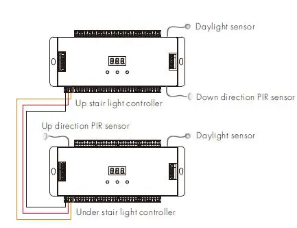
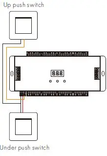
Two Push switches as up/down induction signal input connection
The under push switch connect the cascade UP port of the stair light controller. The up push switch connects the cascade DW port of the stair light controller. The push switch operation will ignore the daylight sensor threshold setting. When the push switch function be set as cascade input/output, the push operation will start the induction light control process. When the push switch function be set as a light on input, the push operation will turn on all light, and the light will turn off after 20s(@speed 8) automatically. For speed 1-8 level, the turn-off delay time is 90/80/70/60/50/40/30/the 20s respectively.