OPTONICA 6385 PIR Sensor Stair Light Controller
PIR Sensor Stair Light Controller
SKU: 6385
PIR sensor/Daylight Sensor/Max 32 step/Compatible with 27 kinds IC/Max 960 pixels/OLED display
Features
- Multiple function PIR sensor stair light controller with daylight sensor.
- 32 channels constant voltage output drive low voltage LED strip, Max. 1A current per channel.
- 2 groups SPI(TTL) signal output, drive 27 kinds IC digital RGB LED strip, IC type and R/G/B order can be set. Compatible ICs: TM1803, TM1804, TM1809, TM1812, UCS1903, UCS1909, UCS1912, UCS2903,
UCS2909, UCS2912, WS2811,WS2812, TM1829, TM1914A, GW6205, GS8206,GS8208,LPD6803, LPD1101, D705, UCS6909, UCS6912, LPD8803, LPD8806, WS2801, WS2803, P9813, SK9822. - Easy operation with OLED display and 3 buttons.
- four work light mode selectable.
- Two stair light controller can cascade.
- Built-in multiple color mode, speed and brightness 1-8 grade adjustable.
- Push switch can also be as induction signal input.
- With fast self-testing function.
- Any damaged LED channel in 32 channels can be set disable.
Technical Parameters
| Input and Output | |
| Input voltage | 5-24VDC |
| Output voltage | 32 x (5-24)VDC |
| Output current | 32CH,1A/CH |
| Output power | 32 x (5-24)W |
| Output type | Constant voltage + SPI(TTL) |
| Safety and EMC | |
| EMC standard (EMC) | ETSI EN 301 489-1 V2.2.3 ETSI EN 301 489-17 V3.2.4 |
| Safety standard(LVD) | EN 62368-1:2020+A11:2020 |
| Certification | CE,EMC,LVD |
| Environment | |
| Operation temperature | Ta: -30 C ~ +55 C O O |
| Case temperature (Max.) | T c:+85O C |
| IP rating | IP20 |
| Sensor data | |
| Sensitive field | ⩽3m |
| Sensitivity angle | 120
|
| Warranty and Protection | |
| Warranty | 3 years |
| Protection | Reverse polarity |
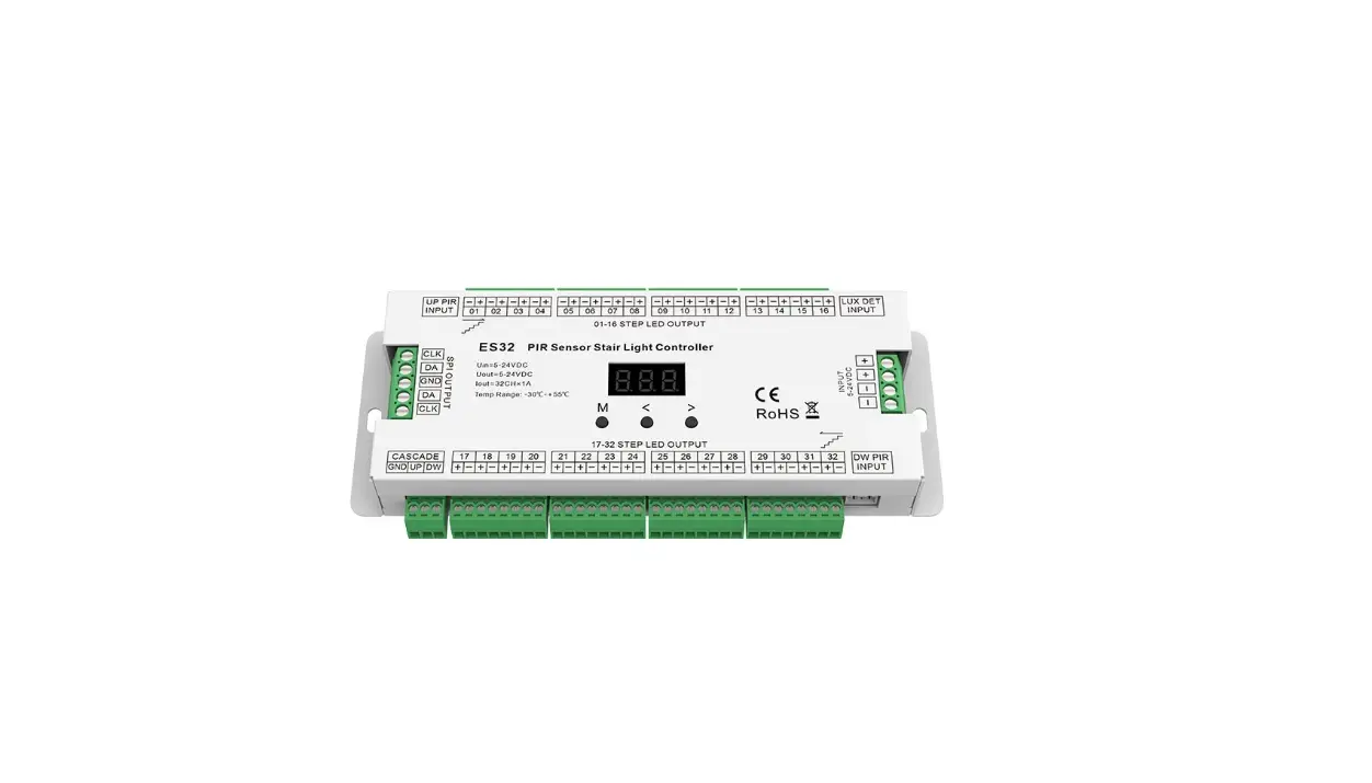
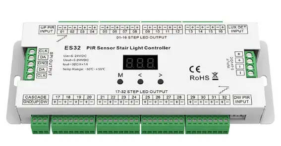
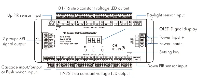
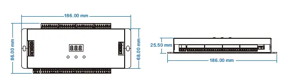
Mechanical Structures and Installations

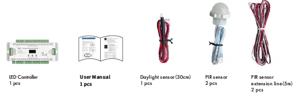
Accessories
Wiring Diagram
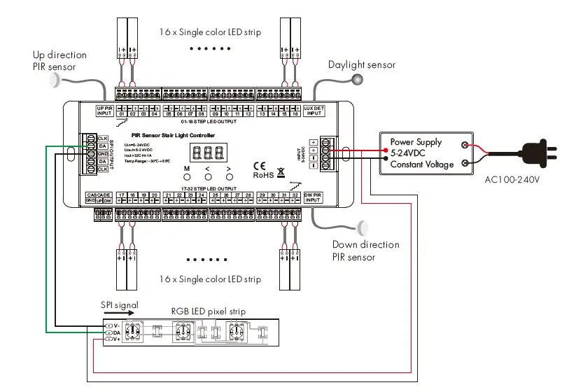
Note: The LED pixel strip also use separate power supply.
OLED screen and key operation
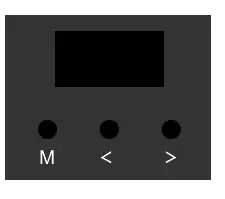
- Short press M key, enter current work light mode parameter setting state.
- Long press M key for 2s, enter system parameter setting state, to switch four work light mode, set light off mode, set push switch input function, set chip type and RGB order, set daylight sensor threshold.
- When in parameter setting state, short press M key to switch between multiple parameter item, press < or > key for parameter adjustment.
- Long press M key or wait 15s to quit parameter setting state.
- Long press M & > key for 2s, start up direction induction light testing.
- Long press M & < key for 2s, start down direction induction light testing.
- Long press < & > key for 2s, restore factory default parameter.
- Long press <, > & M for 2s, enter 32 channels LED disable setting interface.
- The fourth line display color mode name defaultly, and will display induction signal input indication or light on/off state.
- When induction light control process is over, the light will turn off after 10s(@speed 8) automatically. For speed 1-8 level, the turn off delay time is 45/40/35/30/25/20/15/10s respective
System parameter setting
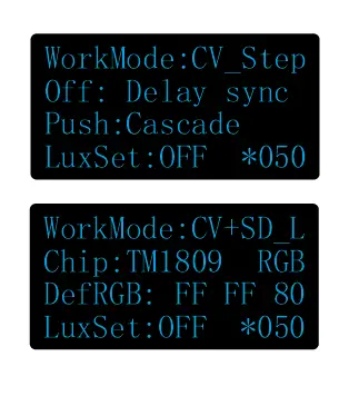
- WorkMode: Switch between four work light mode.
- CV_Step: Only multiple constant voltage LED strip light mode.
- SD_Line: Only 1 or 2 straight line digital pixel LED strip light mode.
- SD_Step: Only multiple Z-shape digital pixel LED strip light mode.
- CV+SD_L : Multiple constant voltage LED strip + 1 or 2 straight line digital pixel LED strip light mode.
- Off: Switch between two light turn off mode when induction light control process is over.
- Delay sync: The light turn off at the same time after the delay time.
- One by one: The light turn off one by one from the tail end.
- Push: Switch between two push switch function.
- Cascade: The push switch input work as cascade input/output or simulate PIR inductive input.
- Light on: The push operation will turn on all light and turn off automatically after the delay time.
- Chip: Switch between 10 class chip (below table) and 6 kinds RGB order (RGB,RBG,GRB,GBR ,BRG,BGR). These parameter is valid only for the work mode with SPI signal output.
- DefRGB: RGB hex value for user-define color. The parameter is valid only for the work mode with SPI signal output.
- LuxSet: Daylight sensor threshold or disable (10, 30, 50, 100, 150, 200lux,OFF), With sufficient ambient light, the PIR sensor does not turn on the light. The digital value after * is current detected LUX value.
Digital pixel RGB LED strip compatible IC type list: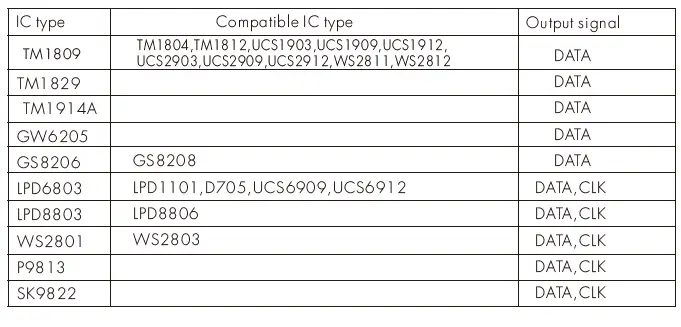
Constant voltage LED strip light mode
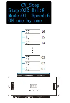
- Step: Total step number, 008-032
- Mode: White mode number, 01-03
- Bri: Brightness grade, 1-8, 8 is the brightest level.
- Speed: Speed grade, 1-8, 8 is the fastest speed.
White mode list:
| No. | Name |
| 01 | ON one by one |
| 02 | All OFF,Five ON |
| 03 | All ON,one OFF |
LED channel output disable setup: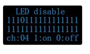
For example: If the fourth channel output is damaged,please long press M ,< & > key to enter LED disable interface, then change the corresponding channel(04) from 1(on) to 0(off). namely the damaged channel can be ignored.
Straight line digital pixel LED strip light mode
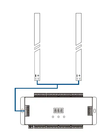
- Dot: Pixel dot number, 032-960
- Mode: Color mode number, 01-12
- Bri: Brightness grade, 1-8, 8 is the brightest level.
- Speed: Speed grade, 1-8, 8 is the fastest speed.
Color mode list:
| No. | Name |
| 01 | Red |
| 02 | Orange |
| 03 | Yellow |
| 04 | Green |
| 05 | Cyan |
| 06 | Blue |
| 07 | Purple |
| 08 | White |
| 09 | Color queue ( 7 color + White) |
| 10 | Color chase( 7 color + White) |
| 11 | Color fade (6 color flow) |
| 12 | Rxxx Gxxx Bxxx (User define) |
S-shape digital pixel LED strip light mode
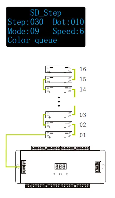
- Step: Total step number, 008-160
- Dot: Pixel dot number of each step, 002-120 The Step number x Dot number must < 960
- Mode: Color mode number, 01-12
- Speed: Speed grade, 1-8, 8 is the fastest speed
Color mode list:No. Name 01 Red 02 Orange 03 Yellow 04 Green 05 Cyan 06 Blue 07 Purple 08 White 09 Color queue ( 7 color + White) 10 Color chase ( 7 color + White) 11 Color fade (6 color flow) 12 Rxxx Gxxx Bxxx (User define)
Constant voltage LED strip + Straight line digital pixel LED strip light mode
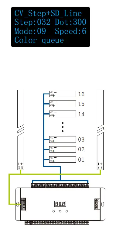
- Step: Total step number, 008-032
- Dot: Pixel dot number, 032-960
- Mode: Color mode number, 01-12 The mode number is used for straight line digital pixel LED strip only. The mode for constant voltage LED strip is fixed On one by one.
- Speed: Speed grade, 1-8, 8 is the fastest speed.
Color mode list:No. Name 01 Red 02 Orange 03 Yellow 04 Green 05 Cyan 06 Blue 07 Purple 08 White 09 Color queue ( 7 color + White) 10 Color chase ( 7 color + White) 11 Color fade (6 color flow) 12 Rxxx Gxxx Bxxx (User define)
Two stair light controller cascade connection
The under stair light controller connect Up direction PIR sensor and daylight sensor. The up stair light controller connect Down direction PIR sensor and daylight sensor. Two stair light controller connect cascade UP/DW line.
The push switch function must be set as cascade input.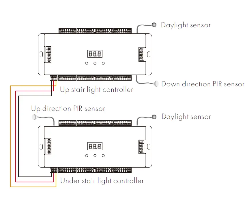
Two Push switch as up/down induction signal input connection
The under push switch connect cascade UP port of the stair light controller. The up push switch connect cascade DW port of the stair light controller. The push switch operation will ignore daylight sensor threshold setting. When the push switch function be set as cascade input/output, the push operation will start induction light control process. When the push switch function be set as light on input, the push operation will turn on all light, and the light will turn off after 20s(@speed 8) automatically. For speed 1-8 level, the turn off delay time is 90/80/70/60/50/40/30/20s respectively.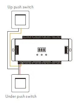
IMPORTER: Prima Group 2004 LTD, Bulgaria, 1784 Sofia, Mladost 1, bl. 144, Ground Floor; Phone: +359 2 988 45 72;


