![]()
Quick Guide
Data Logging Box GPRS GL-G01
Version: 1.0
From this page

H: Contact
If any technical problems, please contact us, with the following information in hand:
- Device model
- Serial number of product
Ningbo Ginlong Technologies Co., Ltd.
No. 57 Jintong Road, Binhai Industrial Park Xiangshan, Ningbo, Zhejiang, 315712, P.R.China
Tel: +86 (0)574 6578 1806
Fax: +86 (0)574 6578 1606
Email: [email protected]
Web: www.ginlong.com
Please record the serial number of your monitor and quote this when you contact us.
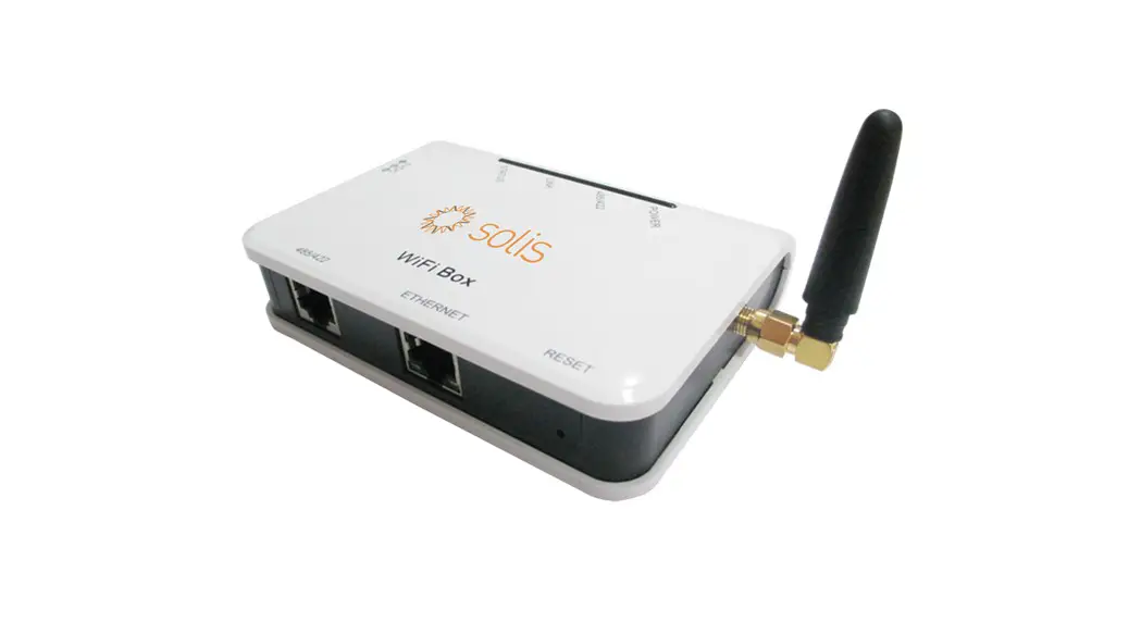
Data Logging Box GPRS is an external data logger in the Ginlong monitoring series.
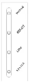
Data Logging Box GPRS can collect information of PV/wind system by GPRS communication through RS485/422 interface with convenient ‘plug and play’ function. With the integrated function, the kit can connect to router and transmit data to the web server, realizing remote monitoring for users. Users can check the runtime status of the device by checking the 4 LED on the panel, indicating Power, 485/422, Link, and Status respectively.
A: Unpack
B : Install data logger
C. Connect data logger and inverters
D. Create Ginlong Home account
E. Create plants
F. Dubug
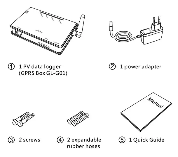
A: Unpack
Checklist
After unpacking the box, please make sure all the items are contained as follows:
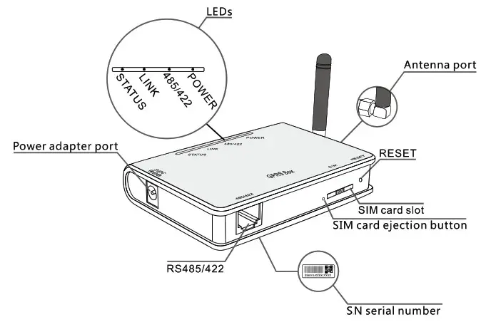
Interface and connection
B: Install data logger
GPRS Box can be either wall-mounted or flatwise.
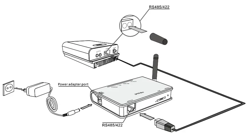
C: Connect data logger and inverters
Notice: Power supply of inverters must be cut off before connection. Make sure that all connections are completed, then power the data
logger and inverters, otherwise personal injury or equipment damage may be caused.
Connection with single inverter
Connect inverter and data logger with network cable, and connect data logger and power supply with power adapter.
Connection with multiple inverters
- Parallel connect multiple inverters with 485 cables.
- Connect all inverters to data logger with 485 cables.
- Set different address for each inverter. For example, when connecting three inverters, the address of first inverter must be set as “01”, the second must be set as “02”, and the third must be set as “03” and so on.
- Connect data logger to power supply with power adapter.
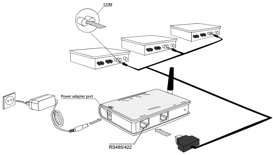
Notice: The connectors of the connection cable may differ according to the brands and models of connected inverters.
Confirm connection
When all connections are finished and with the power on for about 1 minute, check the 4 LEDs. If POWER and STATUS are permanently on, and LINK and 485/422 are permanently on or flashing, connections are suc- cessful. If any problems, please refer to G:Debug.
D: Create Ginlong Home account
Step1: Phone scanning and sending QR code to download registration APP . ( Or search Ginlong Home or Ginlong Pro in the App Store and Google Play Store )
 |  |
| http://www.ginlongmonitoring.com/GinLongProDownload | |
Step2: Click to register.

Step3: Fill in the content as required and click on the register again.

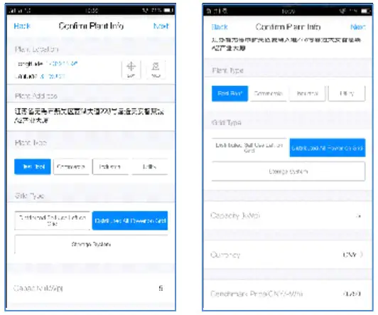
E: Create plants
- In the absence of login, click “1 minute to create the power station” in the center of the screen. Click “+” in the upper right corner to create the power Station.

- Scan the code
APP only supports the scanning of the bar code/QR code of dataloggers. If there is no data logger, you can click the “no device” and jump to the next step: input plant information. - Input plant information
The system automatically locates the location of the station via the mobile phone GPS. If you are not in the site, you can also click “map” to select on the map.
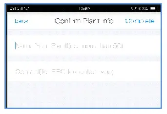
- Enter the name of the station and the owner’s contact number
The name of the station is suggested to use your name, and the contact number is recommended to use your mobile phone number so as to have the installer operation in the later period.

G: Debug
LED indication
| LEDs | Status | Meaning |
| POWER | On | Power is normal |
| Off | Power is abnormal | |
| 485\422 | On | Connection between data logger and inverter is normal |
| Flashing | Data is transmitting between data logger and inverter | |
| Off | Connection between data logger and inverter is abnormal | |
| LINK | On | Data logger connected to server, connection is normal |
| Flashing | Data is transmitting between data logger and server | |
| Off | Connection between data logger and server is abnormal | |
| STATUS | On | GSM module is normal, with strong signal |
| Flashing | GSM module is normal, with general signal | |
| Off | GSM module is normal, with weak signal; or GSM module is abnormal Note: Abnormal means that network is not registered on GSM module |
Trouble shootings
| Phenomenon | Meaning | Solutions | |||
| POWER | 485/422 | LINK | STATUS | ||
| On | On | On | On | Connection is normal, no data transmission | Normal, no solutions required. |
| On | Flashing | Flashing | On | Connection is normal, data is transmitting | Normal, no solutions required. |
| Off | Off | Off | OR | No power supply | Connect power supply and ensure good contacts. |
| On | Off | X | X | Connection with inverter is abnormal | Check the connection cable, and ensure that the cable order comply with T568E1. |
| Ensue the stability of RJ-45. | |||||
| Ensure that Inverter is working under normal condition. | |||||
| On | X | X | Flashing | GSM signal is too weak | Move data logger or adjust the antenna to other position for better signal |
| Antenna is loose | Check if the antenna is loose; if so. please screw to tighten. | ||||
| On | X | X | Of | GSM signal is weak | Move data logger or adjust the antenna to other position with better signal |
| No SIM card or contact of SIM card is abnormal | Take SIM card out and install again. | ||||
| GSM module is abnormal | Power again. | ||||
| PIN password protection applied on SIM card | Disable PIN password protection on SIM card. | ||||
| Account of SIM card out of credit | Check the account of SIM card; If out of credit, please top up. | ||||
| Non-Chinese SIM cad | Please contact your device customer service. | ||||
| On | On | Off | On | Connection to remote server failed | Please contact your device customer service. |
Note 1: X means uncertain status.
Note 2: When screw or adjust the antenna, please note that only the metal part can be touched, and do not screw the plastic part, otherwise the antenna may be damaged.
Note 3: If the equipment still falls to work upon above solutions, please contact your device customer service.
Reset
Press the reset button with a needle or open paper clip and hold for a while when the 4 LEDs should be the same as before. Reset is successful when 3 LEDs, except POWER, turn off.
H: FCC Certification
This device complies with part 15 of the FCC Rules. Operation is subject to the following two conditions: (1) This device may not cause harmful interference, and (2) this device must accept any interference received, including interference that may cause undesired peration.
FCC warning:
Any Changes or modifications not expressly approved by the party responsible for compliance could void the user’s authority to operate the equipment.
Note: This equipment has been tested and found to comply with the limits for a Class B digital device, pursuant to part 15 of the FCC Rules. These limits are designed to provide reasonable protection against harmful interference in a residential installation. This equipment generates uses and can radiate radio frequency energy and, if not installed and used in accordance with the instructions, may cause harmful interference to radio communications. However, there is no guarantee that interference will not occur in a particular installation. If this equipment does cause harmful interference to radio or television reception, which can be determined by turning the equipment off and on, the user is encouraged to try to correct the interference by one or more of the following measures:
- Reorient or relocate the receiving antenna.
- Increase the separation between the equipment and receiver.
- Connect the equipment into an outlet on a circuit different from that to which the receiver is connected.
- Consult the dealer or an experienced radio/TV technician for help.
This equipment complies with FCC radiation exposure limits set forth for an uncontrolled environment. This equipment should be installed and operated with minimum distance 30cm between the radiator & your body.


