B medical systems TOLOGG-3.3-GL Configurable Electronic Logger User Manual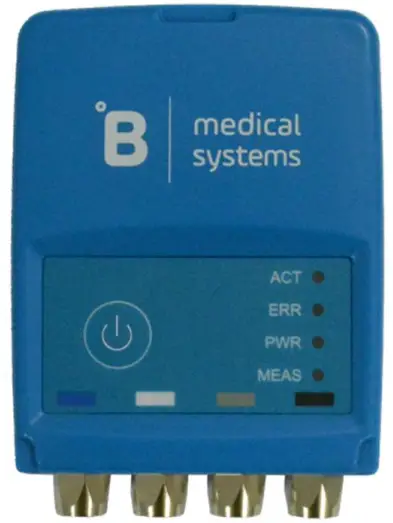
Overview
TOLOGG-3.3-GL is a configurable electronic logger for monitoring storage condition in vaccine refrigerators. It is a small GSM/UMTS and GPS logger with two temperature sensors (internal and external) and a door sensor. It measures and transmits the collected data online to a web server called ‘Temperature Monitoring System”.
With TOLOGG-3.3-GL the user can monitor their refrigerators or freezers and increase the efficiency of storage management.
Main features:
- two temperature sensors
- one open door sensor
- minimum 7 day operation of the battery
- 60 days of data storage
- wide power supply range
Presentation
Logger
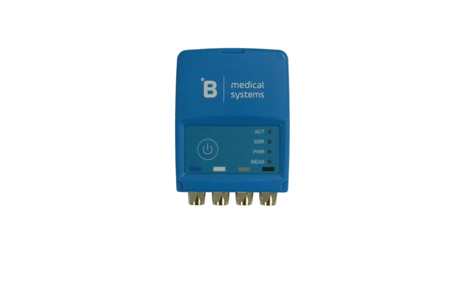
Logger connectors are shown in Figure 1 and described below.
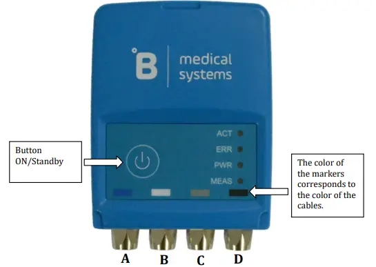
Figure 1 Connectors’ description
A – Internal temperature sensor connector
B – External temperature sensor connector
C – Door sensor connector
D – Power supply connector
The button is used to turn on a device and switch to standby mode In mode standby the device is charging the battery, the charge status is indicated by the PWR LED (see chapter 2.3. Led indications). It is possible to switch from standby mode to on mode remotely using the service application.
There are four markers on the bottom of each logger panel which help to connect the appropriate cable:
- Blue – internal temperature sensor
- White – external temperature sensor
- Gray – door sensor
- Black – power cable
NOTE: At the end of logger installation, dust covers should be applied to unused connectors, see paragraph 1.8. Dust cover
Accessories
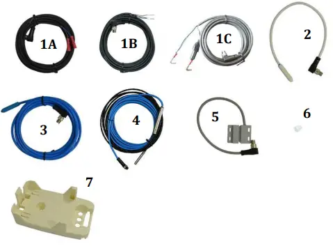
Figure 2. Logger accessories
The accessories include:
- Power cable, two possible variants of termination and cable with fuse
- External temperature sensor
- Internal temperature sensor
- Internal temperature sensor up to -80°C
- Door open sensor
- Dust cover
- Mounting holder
Power supply cable
The power supply cable needs to be screwed to the logger connector (black marker). Connect the power supply cable to the internal power supply ofthe monitored refrigerator.
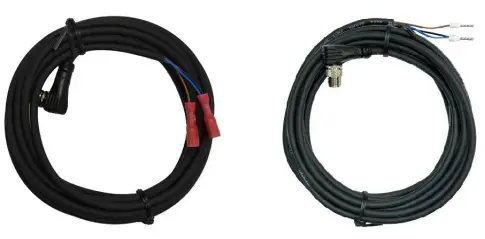
Figure 3. Power supply cables
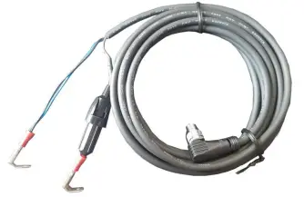
Figure 4. Power supply cable with fuse
Temperature sensors
The figures below present two temperature sensors. The blue sensor is intended to measure the temperature inside cooling devices. The white sensor measures the temperature outside cooling devices.
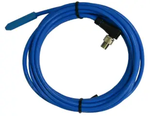
Figure 5. Internal temperature sensor
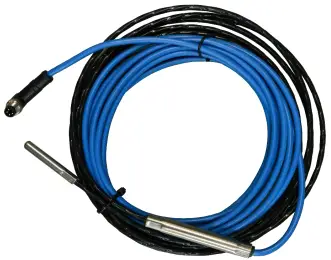
Figure 6. Internal temperature sensor up to -80°C
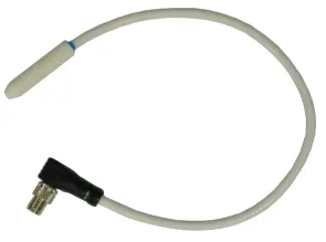
Figure 7. External temperature sensor
The external sensor needs to be fixed to the holder as described in paragraph 1.7. Mounting holder.
The inner sensor needs to be installed into the cooling device as specified by the refrigerator manufacturer.
Door sensor
The door sensor consist of two parts. Sensor (Figure 8 part 2) needs to be fixed to the holder as described in paragraph 1.7. Mounting holder. Magnet (Figure 8 part 1) must be screwed to the refrigerator door.
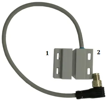
Figure 8. Door sensor
The correct and incorrect positions of the magnet are shown below. When the door is closed, the gap between the magnet and the sensor should not be greater than 3 mm.
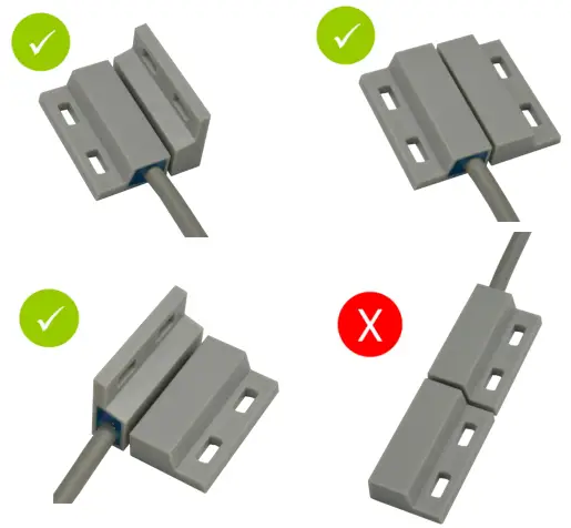
Figure 9. Correct installation of door sensor.
SIM card holder
Logger has an external SIM holder located at the back of device. To insert the SIM card, unscrew the both screws as shown in the Figure 10. Make sure that the cover seal is properly placed as shown in the Figure 11. Insert the SIM card as shown in the Figure 12, place the cover back on the back of the logger and fix it by using both screws.
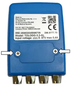
Figure 10. SIM holder
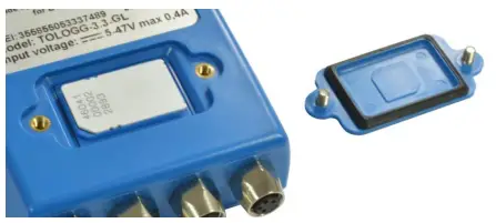
Figure 11. Opened SIM holder – correct position of the seal
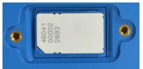
Figure 12. Opened SIM holder – correct position of the SIM card
Mounting holder
The mounting holder (Figure 13) is used to hold the logger outside the cooling device. The holder should be screwed to the wall of the monitored object, and then slide the recorder into the holder. Installation of the handle and the door sensor should be made with tools and screws, adapted to the appropriate material from which the surface to which the handle and the door sensor are mounted.
The holder contains a fixing mechanism for the door sensor and temperature sensor. Figure 14 shows how to fix a temperature sensor, Figure 15 shows how to fix a door sensor.
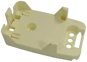
Figure 13. Mounting holder
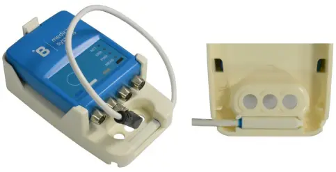
Figure 14. Fixing an outside temperature sensor.
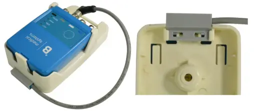
Figure 15. Fixing a door sensor.
Dust cover
Any unused connectors should be protected by dust covers as shown in Figure 16.
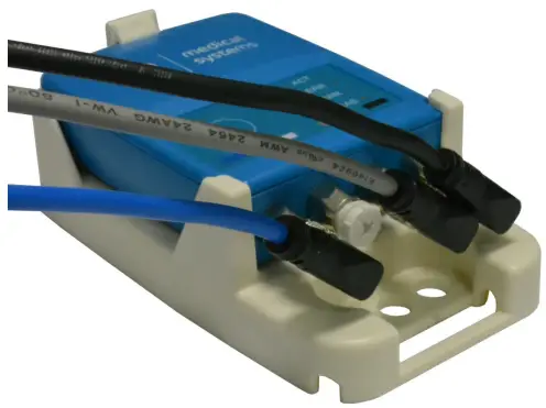
Figure 16. Dust covers installation.
Getting started
Turning on the logger
To turn on the logger, please press and hold the button until MEAS and ACT LEDs will both light up, then release the on/off button. After that the LED ACT will flash quickly, until the initial procedure ends.
For GPS location, the first activation has to be done outside the building. Please turn on the logger and leave it outside for at least 20 minutes.
Turning off the logger
To turn off the logger, please press and hold the button until MEAS and ACT LEDs will both light up, then release the on/off button. After that the LED ACT will flash quickly and the MEAS will stay on, until all measurements are sent to the server.
Led indications
The logger has LED indicators as described in Table 1 and Table 2.
Table 1. LED descriptions
| Name | Color | Description |
| ACT | Green | Indicates logger activity |
| ERR | Red | Indicates the alarm temperature level in the fridge |
| PWR | Yellow | Indicates the connection of an external power source |
| MEAS | Green | Indicates the correct temperature level in the fridge |
Table 2. LEDs indications descriptions
| LEDs | Description | |||
| ACT | ERR | PWR | MEAS | |
| Flashes every 3 sec | – | – | – | Normal operation. |
| Flashes every 0.5 sec | – | – | – | Communication with the server. |
| – | – | – | Flashes every 3 sec | Internal temperature sensor is in normal range |
| – | – | – | Off | Internal temperature sensor is not connected |
| – | Flashes every 1 sec | – | – | Alarm state due to internal sensor temperature below the normal range |
| – | Flashes two times every 1 second | – | – | Alarm state due to internal sensor temperature above the normal range |
| – | – | On | – | External power is connected. |
| – | – | Off | – | External power is disconnected. |
| – | – | Flashes 1 time every 3 seconds | – | Battery level > 50% |
| – | – | Flashes two times every 3 seconds | – | Battery level < 50% |
| – | – | Flashes one time every 1 second | – | Alarm state due to low battery level |
Diagnostic mode
In diagnostic mode it is possible to check a status of:
- GPS position
- battery charge
- connection to server
To enter into diagnostic mode, please press the button 5 times within 3 seconds. The LEDs will show the diagnostic status as follow:
ACT LED will light green if the logger has found a valid GPS position. ERR LED will light red if the logger has not found a valid GPS position yet.
Table 3. ACT and ERR LEDs description during diagnostic mode
| LED | Behavior | Description |
| ACT | Light green | Logger received the correct GPS position |
| ERR | Light red | Logger not found a GPS position yet |
“MEAS” LED will be flashing as described in a table below.
Table 4. Description of the MEAS LED indication
| MEAS LED behavior | Description | Possible reason |
| No flash | Diagnostic information not available. | There is no valid connection yet. Functionality is available from firmware version 2.4.2017092001. |
| 1 flash | No connection. | SIM not inserted. SIM card with PIN. Fail during read of SIM. No GSM coverage. |
| 2 flashes | Data sent by SMS. | Weak GSM coverage. |
| Lights up for 4 seconds | Successful sent of data. |
“PWR” LED will be flashing as described in a table below.
Table 5. Description of the PWR LED indication
| PWR LED behavior | Description | Range |
| 1 flash | Battery discharged | < 20% |
| 2 flashes | Battery needs to be charged | 20% – 50% |
| 3 flashes | Sufficient battery charge | 50 % – 100% |
| 4 flashes | Battery fully charged | 100% |
Technical characteristic
Power supply
The power characteristics are shown in the following table:
Table 6. Power supply
| Parameter | Value |
| Power supply range | 5 to 47 V DC |
| Max. power | 2.5 W |
| Max. current consumption | 400 mA |
| Internal battery | Lithium polymer Capacity: 980 mAh |
Logger without external power supply will operate on battery power for at least 7 days.
Logger is charging the internal battery at temperatures from 0 to 43°C.
RF characteristics
TOLOGG-3.3-GL supports the frequencies described in a table below. Please make sure that the logger can be used in your country and for your network provider.
Table 7. Operating frequencies
| Network technology | Operating frequencies |
| UMTS | 800/850/900/1900/2100 MHz |
| GSM | 850/900/1800/1900 MHz |
Mechanical characteristics
Mechanical characteristics are shown in the table below:
Table 8. Mechanical characteristics
| Parameter | Description |
| Max. dimensions | 68 x 95 x 25 mm (without connectors) |
| Weight | 105 g |
| IP rating | IP65 |
Environment
Environmental characteristics of the TOLOGG-3.3-GL logger are shown in the table below:
Table 9. Environmental requirements
| Parameter | Minimum | Maximum |
| Operating temperature range | -30°C | 60°C |
| Storage temperature | -40°C | +85°C |
| Humidity | 0% | 95% |
Temperature sensors’ characteristics
Characteristics of both the temperature sensors are shown in the below table:
Table 10. Temperature sensor characteristics
| Parameter | Value |
| Measuring range | -30 to +60°C |
| Accuracy | ±0.4 °C |
| Resolution | ±0.1 °C |
Product identification label
Product identification labels are on the logger and on the box of the product. They include the following information:
- manufacturer name and address
- QR code
- WEEE directive symbol (crossed out wheelie bin)
- the CE marking
- FCC ID
- Serial number (IMEI)
- Product number
- Logger model
- Input voltage range and power consumption
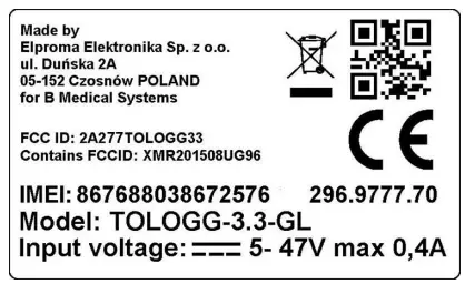
Figure 17. Logger label
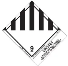
Transport restrictions
- During transport by air, loggers must be turn off.
- There is no additional restriction, if you want to transport by air no more than two loggers in one package.
- If you want to transport by air more than two loggers in one package, you have to follow:
- maximal number of loggers in one package cannot be bigger than 250
- package has to be labeled with sign: UN3481

- Logger contains Lithium-polymer accumulator. Therefore please contact your courier company for additional requirements.
B Medical Temperature Monitoring System
The Temperature Monitoring System is described in a separate document “B Medical Temperature Monitoring System” manual.
Troubleshooting
- No data in the Temperature Monitoring System or no SMS received:
- Logger battery is too low – please connect the power cable and the external power supply to the cable
- The Logger is turned OFF – please press and hold the button to turn on the logger.
- GSM/UMTS signal out of range – move the logger to an area with sufficient GSM/UMTS signal strength.
- No logger position on the map in the Temperature Monitoring System:
- No GPS signal reception – move logger to an area with sufficient GPS signal(outside the building), turn it OFF and turn it ON again.
Certification
FCC Information
This device complies with Part 15 of the FCC Results. Operation is subject to the following two conditions:
(1) This Device may not cause harmful interface, and
(2)This Device must accept any interference received, including interference that may cause undesired operation.
Note : This equipment has been tested and found to comply with the limits for CLASS B digital device, pursuant to Part 15 FCC Rules. These limits are designed to provide reasonable protection against harmful interference when the equipment is operated in a commercial environment. This equipment generates, uses and can radiate radio frequency energy and, if not installed and used in accordance with the instructions, may cause harmful interference to radio communications.
However, there is no guarantee that interference will not occur in a particular installation. If this equipment does cause harmful interference to radio or television reception, which can be determined by turning the equipment off and on, the user is encouraged to try correct the interference by one or more of the following measures:
- Reorient or relocate the receiving antenna.
- Increase the separation between the equipment and receiver.
- Connect the equipment into an outlet on a circuit different from that to which receiver is connected.
- Consult the dealer or experienced radio/TV technician for help.
WARNING
Changes or modifications not expressly approved by the manufacturer could void the user’s authority to operate the equipment.
Safety recommendations
READ CAREFULLY
- Be sure the use of this product is allowed in your country and that you have appropriate environmental conditions. The use of this product may be dangerous and has to be avoided in the following areas:
- where it can interfere with other electronic devices in environments such as, aircrafts, etc.
- where there is a risk of explosion such as petrol stations, oil refineries, etc.
- It is the responsibility of the user to enforce the country’s regulation and the specific environmental regulations.
- Do not disassemble the product. Any sign of tampering will compromise the validity of the warranty.
- Follow the instructions of the hardware user guides for the correct wiring of the product.
- The product has to be supplied with a stable voltage source and the wiring has to conform to the security and fire prevention regulations.
- The system integrator is responsible for the functioning of the final product. Should there be any doubt, please refer to the technical documentation and the regulations in force.
- Do not dispose of the logger in a fire, as it may cause an explosion.
- Installation should be made with tools and screws, suitable to the material, to which they will be fixed.
- RF EXPOSURE WARNING: When the logger is on, keep the distance of 20cm between the device and the body.


