![]() TTP-A-6HW Rotary Vane Vacuum Pump
TTP-A-6HW Rotary Vane Vacuum Pump
Instruction Manual
For Models TTP-A-2, TTP-A-3, TTP-A-4, TTP-A-4HW, TTP-A-6, and TTP-A-6HW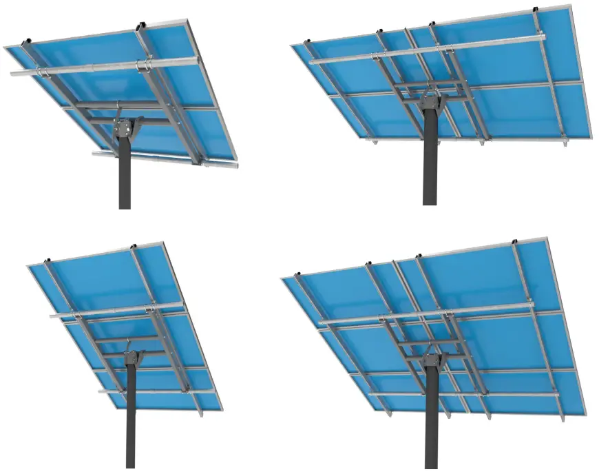
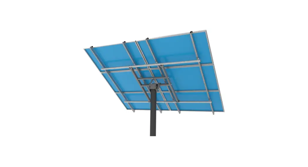
TTP-A-6HW Rotary Vane Vacuum Pump
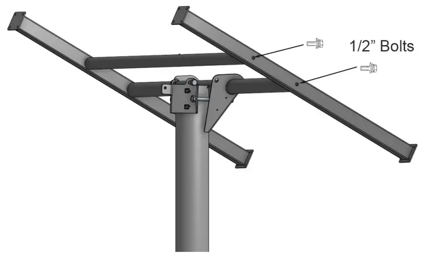
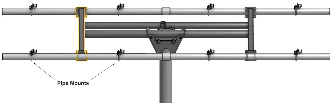
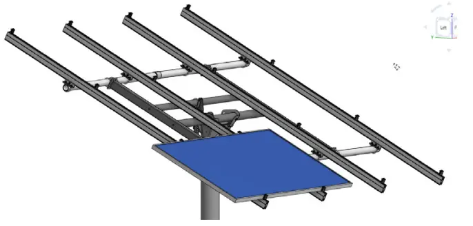
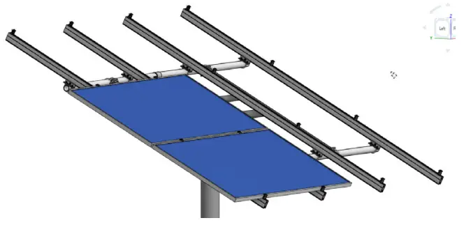
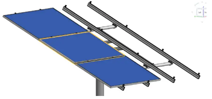
Note: 2-inch horizontal steel pipes shown in the pictures above are not included. Purchase localy or from us.
TTP-A-2 2 Module Top of Pole Mount
TTP-A-3 3 Module Top of Pole Mount
TTP-A-4 4 Module Top of Pole Mount
TTP-A-4HW 4 Module High Wind Top of Pole Mount
TTP-A-6 6 Module Top of Pole Mount
TTP-A-6HW 6 Module High Wind Top of Pole Mount
Scan the QR Code below to see an animated video of the assembly of this mount
 https://instructions.online/?id=1424-cb%20no%20hoist
Disclaimer
This manual describes proper installation procedures and provides necessary standards required for product reliability. Warranty details are available on our website. www.tamaracksolar.com
All installers must thoroughly read this manual and have a clear understanding of the installation procedures prior to installation. Failure to follow these guidelines may result in property damage, bodily injury or even death.
Structural parts of this mount are made with painted steel which will show signs of rust in areas that get scratched during assembly. It is good practice to repaint scratched parts after assembly.
Installer Responsibilities
- Follow all applicable local or national building and fire codes, including any that may supersede this manual.
- Electrical installation should be conducted by a licensed and bonded electrician or solar contractor.
- Module maintenance or removal must not break the bonding path of the system.
- Ensure all products used are appropriate for the installation and array under the site’s loading conditions.
- Use only Tamarack parts or parts approved by Tamarack; substituting parts may void any applicable warranty.
- Comply with all applicable fire codes including, but not limited to, keeping walkways clear.
- Ensure bare copper grounding wire does not contact aluminum and zinc-plated steel components, to prevent risk of galvanic corrosion.
- If loose components or loose fasteners are found during periodic inspection, retighten immediately. If corrosion is found, replace affected components immediately.
- Provide an appropriate method of direct-to-earth grounding according to the latest edition of the National Electrical Code, including NEC 250: Grounding and Bonding, NEC 690: Solar Photovoltaic Systems, and CSA C22.1, Safety Standard for Electrical Installations, Canadian Electrical Code, Part 1
- Disconnect AC power before servicing or removing micro inverters and power optimizes.
- Review module manufacturer’s documentation to ensure compatibility and compliance with warranty terms and conditions.
- Maximum Series Fuse Rating is 20 Amps.
Tools Required
- 1 1/8-inch Socket
- 1-1/8-inch Wrench
- 3/4-inch Socket
- 9/16-inch Socket
- 1/2-inch Socket
- Ratchet to fit Sockets
- Crescent Wrench
- Torque Wrenches (settings range from 6 to 100 foot-pounds. This may require multiple wrenches)
- Tape Measure
- Angle Finder
- Compass
- Ladder
TTP-Series Pole Mount Components
| Part Description | TTP-A-2 | TTP-A-3 | TTP-A-4 | TTP-A-4HW | TTP-A-6 | TTP-A-6HW | |
| Cap Assembly – 4-inch | Pole Cap, Pivot 4-inch pipe, 2.5-inch holes | 1 | 1 | ||||
| Pole Cap 4-inch Backplate | 1 | 1 | |||||
| Array Tilt Adjuster Arm | 1 | 1 | |||||
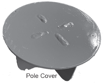
| Pole Top Cover 4-inch | 1 | 1 | |||||
| Pole Cap Bolts 3/4 -10 x 7-inch | 1 | 1 | |||||
| Pole Cap Top Support Bolt 3/4-10 x 6-inch | 1 | 1 | |||||
| Pole Cap Flange Nut 3/4-10 | 1 | 1 | |||||
| Set Bolts 1/2 -13 x 1-1/2inch | 1 | 1 | |||||
| Hex Bolt 1/2-13 x 1-1/2-inch for Adjuster | 1 | 1 | |||||
| Flange Nut ½ – 13 for Adjuster | 1 | 1 | |||||
| Adjuster U-Bolt ⅜” x 2-1/2-inch | 1 | 1 | |||||
| Cap Assembly – 6-inch | Pole Cap, Pivot 6-inch pipe, 2.5-inch holes | 1 | 1 | 1 | 1 | ||
| Pole Cap 6-inch Backplate | 1 | 1 | 1 | 1 | |||
| Array Tilt Adjuster Arm | 1 | 1 | 1 | 1 | |||
| Pole Top Cover 6-inch | 1 | 1 | 1 | 1 | |||
| Pole Cap Bolts 3/4 -10 x 9-inch | 2 | 2 | 2 | 2 | |||
| Pole Cap Top Support Bolt 3/4-10 x 8-inch | 1 | 1 | 1 | 1 | |||
| Pole Cap Flange Nut 3/4-10 | 3 | 3 | 3 | 3 | |||
| Set Bolts 1/2 -13 x 1-1/2 inch | 6 | 6 | 6 | 6 | |||
| Hex Bolt 1/2-13 x 1-1/2-inch for Adjuster | 1 | 1 | 1 | 1 | |||
| Flange Nut ½ – 13 for Adjuster | 1 | 1 | 1 | 1 | |||
| Adjuster U-Bolt ⅜” x 3-1/8-inch | 1 | 1 | 1 | 1 | |||
| H-Frame – 90439 | Rectangular Tube 3×2 x 0.12 wall | 1 | 1 | 2 | 2 | ||
| Rectangular Tube 3×2 x 0.188 wall | 2 | 2 | |||||
| Support Pipe 2-inch Sch 40 | 1 | 1 | 1 | 1 | |||
| Support Pipe 2-inch Sch 80 | 1 | 1 | |||||
| Pivot Pipe 2.5-inch Sch 40 | 1 | 1 | 1 | 1 | |||
| Pivot Pipe 2.5-inch Sch 80 | 1 | 1 | |||||
| Hex Bolt 1/2-13 x 3-1/2-inch | 1 | 1 | 4 | 4 | 4 | 4 | |
| Flat Washer 1/2-inch | 1 | 1 | 4 | 4 | 4 | 4 | |
| U-Bolt w/Nuts for 2-inch Pipe | 1 | 1 | 8 | 8 | 8 | 8 | |
| 3.1 Rail 85-inch | 4 | 4 | 0 | 0 | |||
| 3.1 Rail 66-inch | 0 | 0 | 8 | 8 | |||
| Module Rail Splice with Bolts and Nuts | 0 | 0 | 2 | 2 | |||
| Module Mounting Rails | Module Mounting Clamp | 8 | 8 | 16 | 16 | 16 | 16 |
| Pipe Mount w/U-Bolt | 4 | 4 | 8 | 8 | 8 | 8 | |
| Module Rail End Caps | 4 | 4 | 8 | 8 | 8 | 8 | |
| Ground Lug | 1 | 1 | 2 | 2 | 2 | 2 | |
| Module Lead Clips | 6 | 6 | 9 | 9 | 9 | 9 |
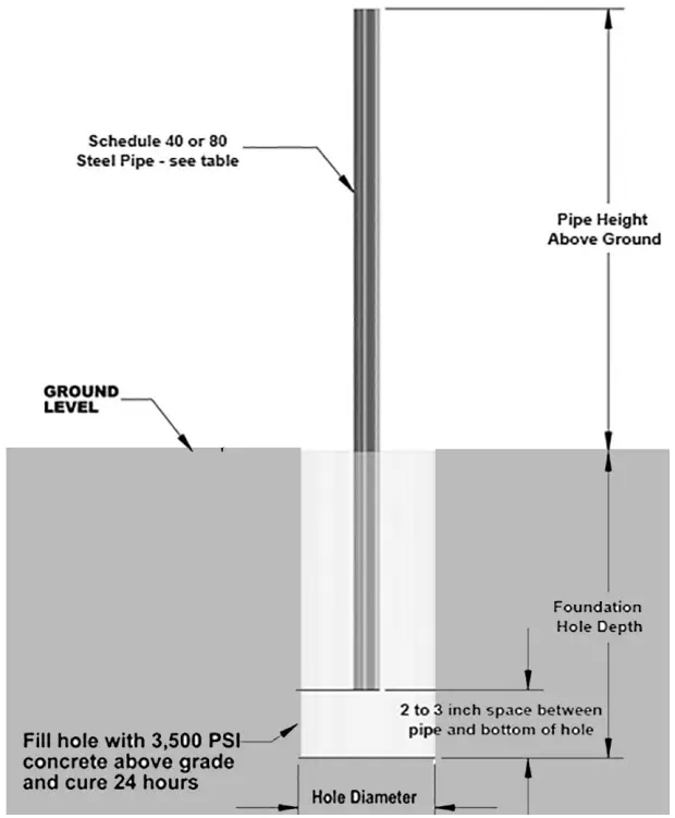
Foundation Hole and Pole Guidelines
- The suggestions below are recommendations only. It is the installer’s responsibility to validate foundation parameters prior to installation, a local geotechnical report may be required to assess soil conditions. We recommend consulting with a local engineer familiar with local regulations and build site requirements, including soil conditions, terrain, and load criteria (wind, snow, seismic). All of these parameters may impact foundation requirements.
- If you are planning to make seasonal adjustments to the solar array angle, use the steepest angle that you plan to use for foundation and pole pipe sizing to insure that the pole and foundation are strong enough to support the array, and that the desired minimum ground clearance is maintained, at all projected angles.
- Highlighted lines in the tables on the next 2 pages require schedule 80 pipe for the main support pipe.
- Dig hole according to recommended depth and diameter. Remove or properly compact any loose material at the bottom of the hole.
- The pole length listed in the following tables are based on having the pole installed 2-3 inches from the bottom of the dug holes. Use a brick, concrete block, tiles, or other non-organic solid material at the bottom of the hole to support the pole on, allowing it to be raised above the bottom of the hole and allowing the concrete to fully encapsulate the pipe pole. If using a thicker material, be sure to allow for the added thickness when calculating the above-ground and total pole lengths.
- Set pole in hole and use a level to insure that it is straight and plumb in all directions.
- Brace pole to prevent movement while pouring concrete. Pouring so that concrete is in direct contact with the soil is recommended. If forming or using sonotube, properly compact backfill. Allow concrete to cure for recommended length of time.
Soil Classifications
- If in doubt about the soil type and holding strength, consult a local engineer.
- Class 3 – Sandy Gravel and/or Gravel – Lateral Bearing Pressure – 200 lbs/sq ft below natural grade
- Class 4 – Sand; silty sand, clayey sand, silty gravel, and clayey gravel – Lateral Bearing Pressure – 150 lbs/sq ft below natural grade
- Class 5 – Clay, sandy clay, silty clay, silt and sandy silt – Lateral Bearing Pressure – 100 lbs/sq ft below natural grade
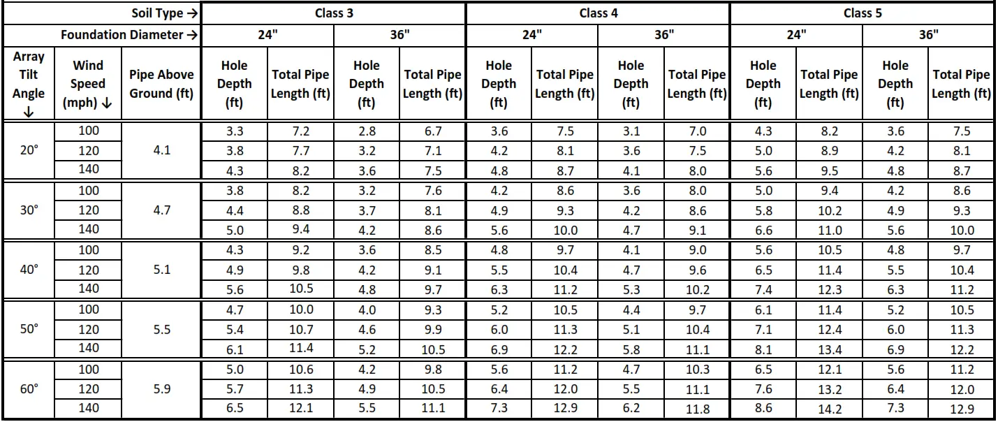
TTP‐2 For Array Ground Clearance of 3 Feet
Foundation Hole Depth, Height of Pole Above Ground and Total Pole Length for Ground Clearance of 3 Feet at Lowest Part of the Array & Exposure Catgory B For Various Soil Class and Foundation Hole Diameter. Vertical Pipe is 4-inch Schedule 40. Highlighted sections in the table below require 4-inch Schedule 80 Pipe.
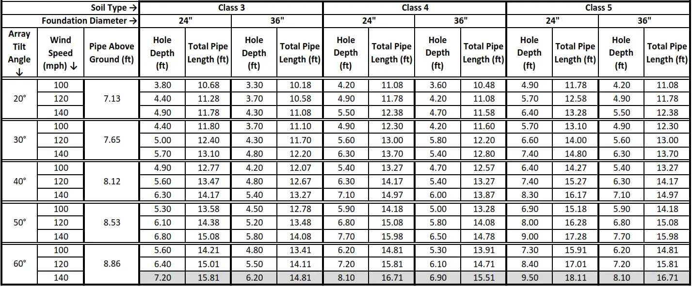
TTP‐2 For Array Ground Clearance of 6 Feet
Foundation Hole Depth, Height of Pole Above Ground and Total Pole Length for Ground Clearance of 6 Feet at Lowest Part of the Array & Exposure Catgory B For Various Soil Class and Foundation Hole Diameter. Vertical Pipe is 4-inch Schedule 40. Highlighted sections in the table below require 4-inch Schedule 80 Pipe.
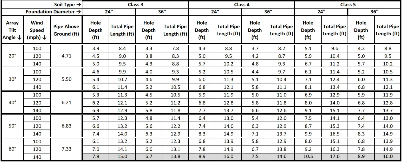
TTP‐3 For Array Ground Clearance of 3 Feet
Foundation Hole Depth, Height of Pole Above Ground and Total Pole Length for Ground Clearance of 3 Feet at Lowest Part of the Array & Exposure Catgory B For Various Soil Class and Foundation Hole Diameter. Vertical Pipe is 4-inch Schedule 40. Highlighted sections in the table below require 4-inch Schedule 80 Pipe.
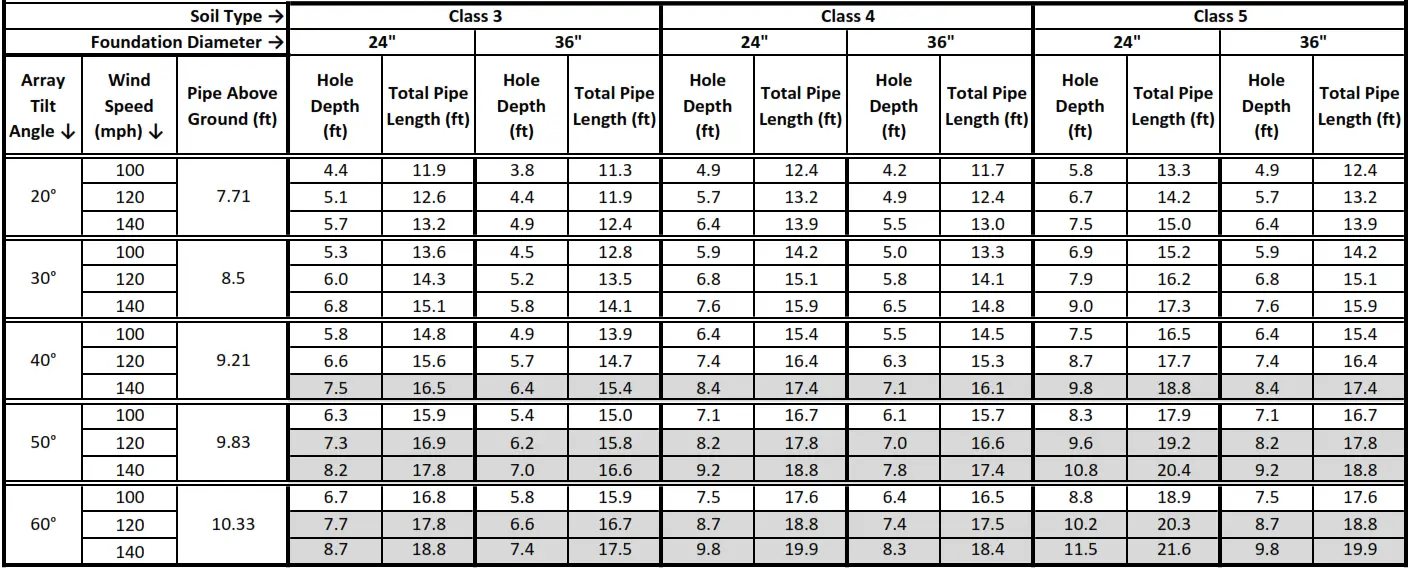
TTP‐3 For Array Ground Clearance of 6 Feet
Foundation Hole Depth, Height of Pole Above Ground and Total Pole Length for Ground Clearance of 4 Feet at Lowest Part of the Array & Exposure Catgory B For Various Soil Class and Foundation Hole Diameter. Vertical Pipe is 4-inch Schedule 40. Highlighted sections in the table below require 4-inch Schedule 80 Pipe.
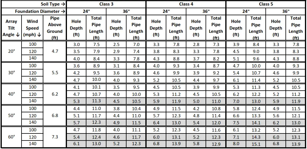
TTP‐4 and TTP‐4HW for Array Ground Clearance of 3 Feet
Foundation Hole Depth, Height of Pole Above Ground and Total Pole Length for Ground Clearance of 3 Feet at Lowest Part of the Array & Exposure Catgory B For Various Soil Class and Foundation Hole Diameter. Vertical Pipe is 6-inch Schedule 40 (Highlighted sections require 6-inch Schedule 80 Pipe)
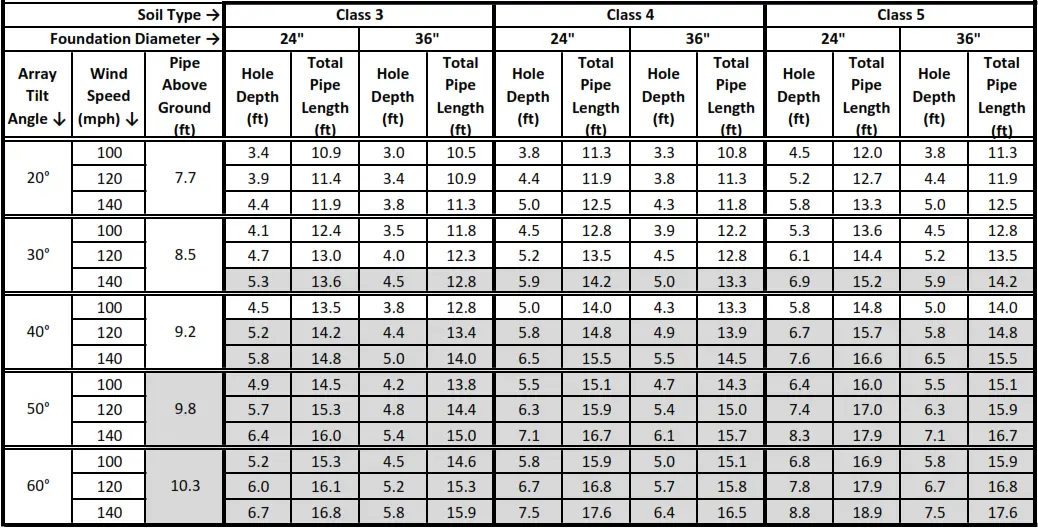
TTP‐4 and TTP‐4HW for Array Ground Clearance of 6 Feet
Foundation Hole Depth, Height of Pole Above Ground and Total Pole Length for Ground Clearance of 6 Feet at Lowest Part of the Array & Exposure Catgory B For Various Soil Class and Foundation Hole Diameter. Vertical Pipe is 6-inch Schedule 40 (Highlighted sections require 6-inch Schedule 80 Pipe)
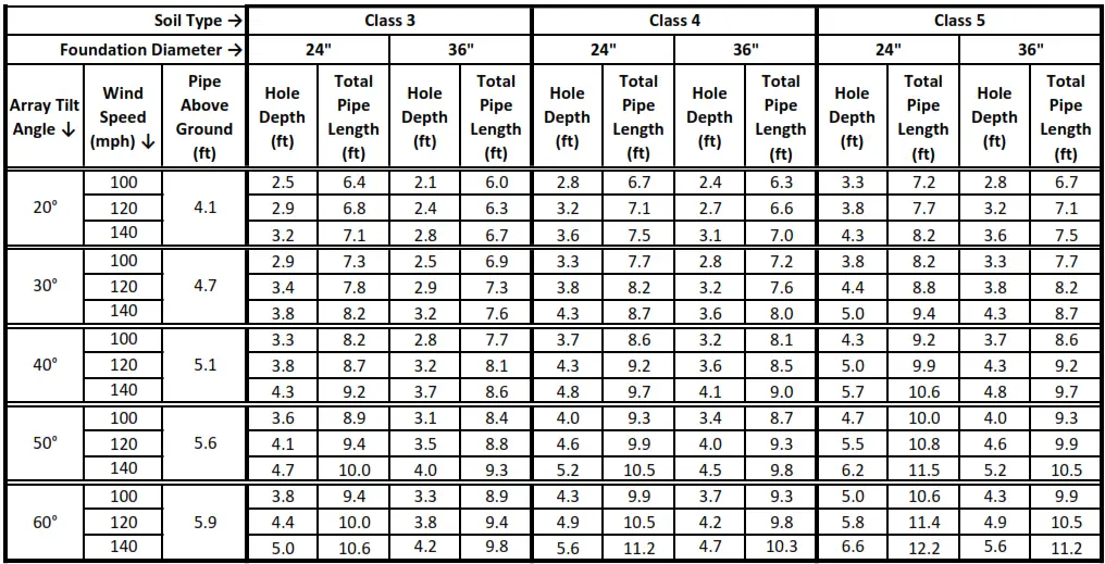
TTP‐6 and TTP‐6HW for Array Ground Clearance of 3 Feet
Foundation Hole Depth, Height of Pole Above Ground and Total Pole Length for Ground Clearance of 3 Feet at lowest part of the array & Exposure Catgory B For Various Soil Class and Foundation Hole Diameter. Vertical Pipe is 6-inch Schedule 40 (Highlighted sections require 6-inch Schedule 80 Pipe)
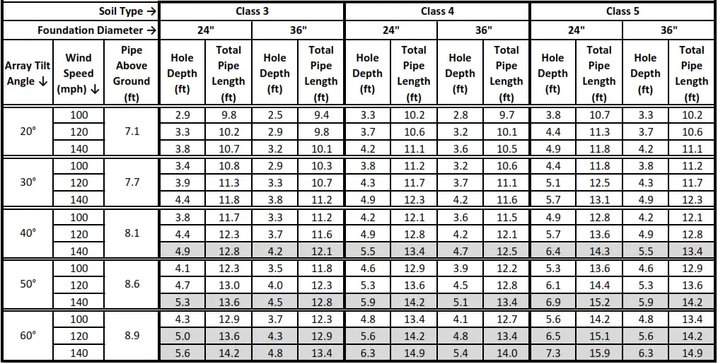
TTP‐6 and TTP‐6HW for Array Ground Clearance of 6 Feet
Foundation Hole Depth, Height of Pole Above Ground and Total Pole Length for Ground Clearance of 6 Feet at lowest part of the array & Exposure Catgory B For Various Soil Class and Foundation Hole Diameters. Vertical Pipe is 6-inch Schedule 40 (Highlighted sections require 6-inch Schedule 80 Pipe)
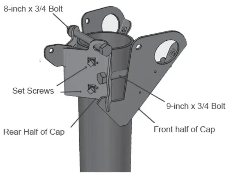
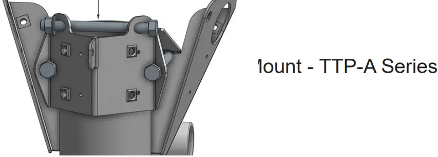
Step One – Pole Cap Assembly
- Place the Pole Cover on top of the mounting pole.

- Put the 3/4 x 8-inch Cap Support Bolt through the two top holes in the rear half of the Pole Cap and install nut and tighten firmly. It is not necessary to torque this bolt and nut. This bolt keeps the Pole Cap at the top of the post.
- Put the two 3/4 x 9-inch bolts into the back half of the Pole Cap, then through the front half and put the nut loosely on the bolt. These large nuts and bolts may be hard to thread together by hand. Start nuts on bolts by hand and use wrenches as needed. Bottoms of the cap will hook together.

- Slide the assembled Pole Cap over the 6-inch vertical pole. The front and back of the cap assembly should be aligned so that the two 9-inch bolts are approximately horizontal and the top edge of the front (larger) part of the cap is against the vertical pole. Rotate the Pole Cap on the post so that the front (larger) half of the Pole Cap is on the side of the pole that the array will be facing.
- Loosely install the four 1/2-inch set screws in the threaded holes on the rear half of the Pole Cap. Do not tighten at this time.
- Securely tighten the two 3/4” bolts in the Pole Cap assembly, keeping them horizontal. Tighten enough that the front of the cap will not slide down the pipe. Do not fully torque to specification until final assembly is complete.

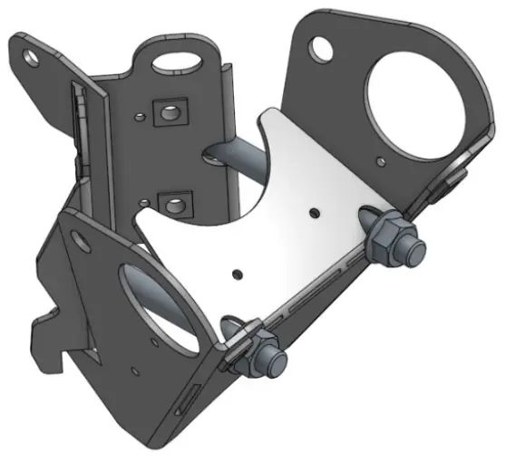
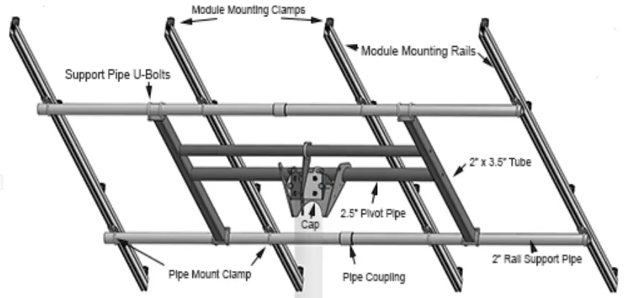
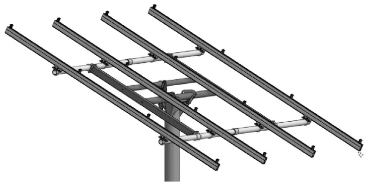
Step Two – Assemble H-Frame
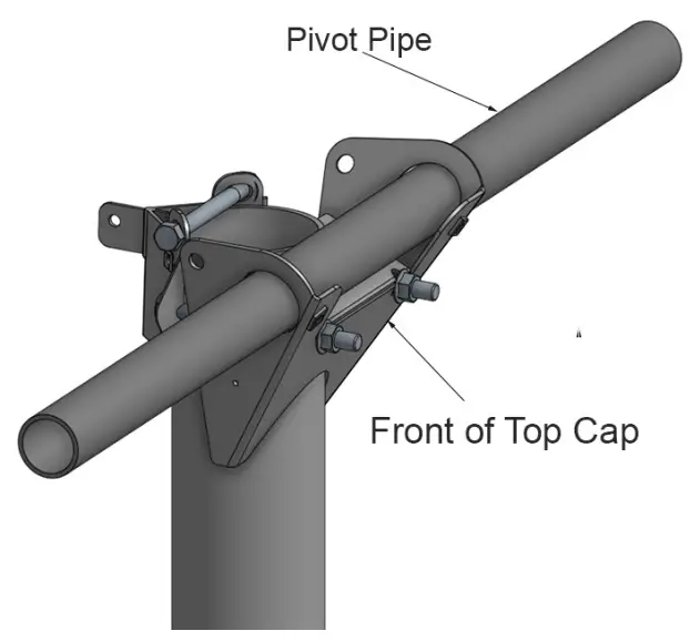
- Slide the 2-1/2-inch Pivot Pipe (2-7/8” O.D.) through the holes on the side of the front half of the Top Cap and center it in the front half of Top Cap.

- Bolt a 2 x 3-inch Tube to each side of the Pivot Pipe with a 1/2 x 3-inch bolt, flat washer and split lock washer. Use the hole in the center of the 2” x 3” Tube.
- Bolt the 2-inch Adjuster Pipe (2-3/8-inch O.D.) between the two 2 x 3-inch Tubes with a 1/2 x 3-inch bolt, flat washer and split lock washer on each side. You should have an assembly that looks like the picture above. Tighten the 4 bolts to 45 ft-lbs.


Step Three – Assemble Adjuster Arm
- Attach the Adjuster Arm to the Adjuster Pipe with a 2-3/8-inch U-bolt and two flange nuts as pictured at right. Tighten hand tight for now.
- Using the hole in the Adjuster Arm which sets the 2 x 3-inch rectangular tubes in an approximately horizontal position for assembly purposes, attach the Adjuster Arm to the tab provided on the rear of the Pole Cap with a 1/2 x 1-inch bolt. Assemble the bolt finger-tight, as the array angle will be readjusted in the final assembly.

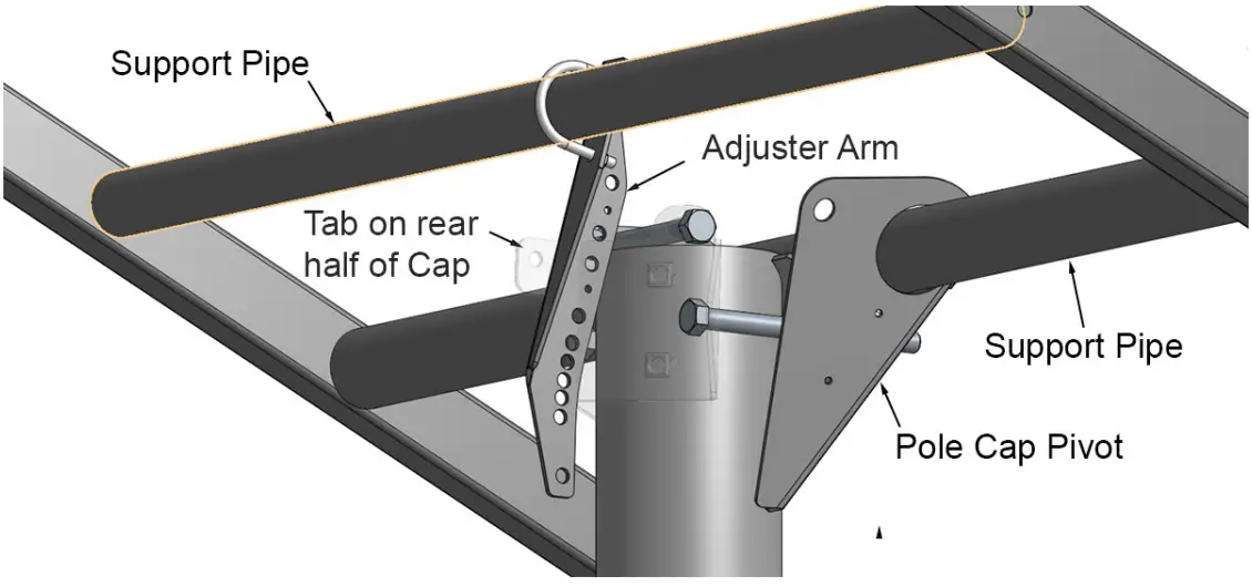
Step Four – Rail Support Pipes
- 4 module and 6 module mounts will need either two 10-foot 2-inch pipes if module length is less than 78-inches or two 12-foot pipes if modules are longer than 78-inches to support four rails. Use schedule 40 pipe for TTP-A-4 and TTP-A-6 mounts. Use schedule 80 pipe for TTP-A-6HW or TTP-A-4HW mounts.
- 2 module and 3 module mounts will need two 5-foot 2-inch schedule 40 pipes to support two rails.
- If you are using one of our 10-foot or 12-foot Pipe Kits, it will come in two sections to make it easier to ship. Connect two of the 2-inch Schedule 40 or 80 x 5-foot long or 6-foot long Rail Support Pipes together using a 2-inch pipe coupling and thigh ten with two pipe wrenches. Repeat with the remaining two 2-inch Schedule 40 or 80 x 5-foot long Rail Support Pipes and coupling. If you purchase pipe locally you can buy pipe that are the correct length without using couplings.
- Attach the assembled Rail Support Pipes to the flat ends of the 2 x 3-inch Rectangular Tubing using two 2-3/8-inch x 1/2-inch U-bolts at the end of each 2 x 3-inch tube. Center these Pipes on the assembly
- Tighten the nuts on the U-bolts to 40 ft-lbs.

Step Five – Module Mounting Rail Assembly
- Two and four module mounts, use the 85-inch long Module Mounting Rails provided.
- Three and six module mounts, are shipped with 132-inch Module Mounting Rails made of 66-inch sections.
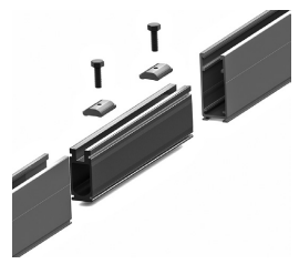
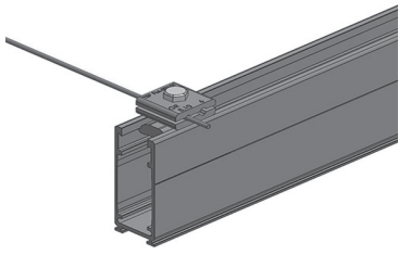
1) Splice two 66-inch rail together using the provided Splice and the two 5/16 x 1.125-inch bolts and Channel Nuts. Slip the Splice 5-inches into the end of one rail section, place a Channel Nut and bolt approximately 2.5-inches from the rail end and tighten. 2) Slide the second section of rail over the splice, butting the two rail ends together, and repeat the Channel Nut installation process with the second Channel Nut and bolt.
3) Repeat the processes in #1 and #2 above with the other three 85-inch and 42.5-inch rail sections and Splices. - Tighten all of the Splice bolts in the four completed 132-inch assemblies to 12 ft-lbs.

 2) Slide the second section of rail over the splice, butting the two rail ends together, and repeat the Channel Nut installation process with the second Channel Nut and bolt.
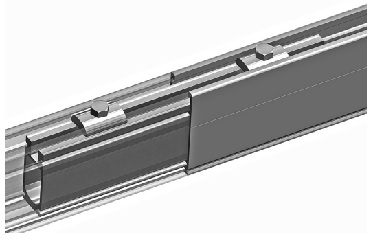
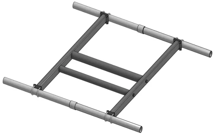
Step Six – Attach Module Mounting Rails
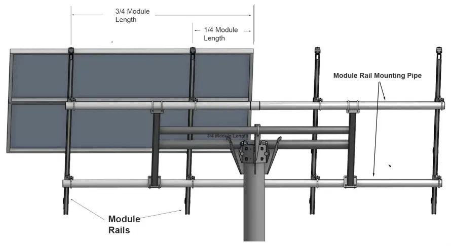
- The Module Mounting Rails should be mounted on the Rail Support Pipes in the location where they will be approximately under the mounting holes in the frame of the PV modules that you are using, or at a position that is 1/4 of the length of the PV module from each end of the module.

- Locate Rail positions on the Rail Support Pipes and place one Pipe Mount on the pipe in these positions. Two and three module mounts will have two rails and four Pipe Mounts. Four and six module mounts are supplied with four rails and eight Pipe Mounts.


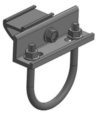
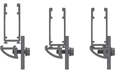
- Place one of the Module Mounting Rails on two of the Pipe Mounts installed on the Rail Support Pipes, center it in the north/south direction so it extends past both Support Pipes the same distance. Make sure that the Pipe Mount slips into both of the mounting features on the bottom of the rails (see drawing at right). Tighten the the 5/16-inch bolts with a 1/2-inch socket to 12 ft-lbs.

- Repeat this for the other Module Mounting Rails.
Step Seven – System Grounding
- Tamarack Module Mounting Rails and the PV module frames are electrically bonded together by the Tamarack Module Clamps. This creates a single electrically bonded unit for grounding purposes per UL 2703 requirements. One Ground Lug is required to provide equipment grounding for each column of PV modules.

- A Ground Lug can be attached at any location desired on either one of the two Module Support Rails in each column.
- Connect both ground lugs to the ground wire in the system according to local code.
Step Eight – Mount PV Modules on Rails
- Before mounting the PV modules to the pole mount, map out where you want the wiring junction boxes, and output cables, on the backs of the modules to be located.

- To center the modules on the rails, calculate the amount of excess Module Mounting Rail length you will have. This is dependent on the width of the PV modules that you are using.
1) Add together the widths of the modules in a column, and add 1/2-inch for each space between the modules in the column.
2) For TTP-4 and TTP-4HW: subtract the above calculated number from 85.
For TTP-6 and TTP-6HW subtract the above calculated number from 132.
3) This will tell you the total excess length of the Module Mounting Rails that you will have based on the width of the particular PV modules that you are mounting. - Start module installation at the bottom of the first column. Measure up the rail by by 1/2 of the distance calculated in #2 above. Place a Module Clamp on each of the Module Mounting Rails at this distance. Be sure to put the side of the top clamp with two bonding pins toward the module frame.

- Center the first module east to west over the rails and hold in place. To allow for at least 1/2-inch of space between the two columns of modules, make sure that the inside edge of the module’s frame is at least 1/4” outward from the center of the Rail Support Pipes. You can use the 2-inch pipe couplings in the assembled Rail Support Pipes to determine where the center is. Make sure that the module is straight and level on the rails and tighten the two end clamp bolts to 108 inch-pounds (9 foot-pounds).

- Install one Module Clamp in each rail on the other side of the first module, and slide it down so that the inside of the clamp contacts the frame of the first module. The springs will hold the clamps in place prior to tightening. Place the second module on the rails, align it with the first module, and slide down and fully into the two mid-clamps. Tighten the mid-clamp bolts to 144 inch-pounds (12 foot-pounds) to fully secure the module.

- Install the third module in the column on TTP-6 or TTP-6HW in the same manner.
- On the top edge of the last module of the first column, install the two Module Clamps so that the sides with the two stainless-steel pins are facing in toward the module frame, and the clamp is tight up against the module frame. Tighten the two end clamp bolts to 108 inch-pounds (9 foot-pounds).
- Install the next column of modules in the same manner. Leave at least 1/2-inch of spacing between the columns.
- Do a final check to be sure that all bolts and installation hardware on the array is properly tightened to the specified torque values.
Final Assembly
- To set the array tilt to the desired angle, remove the previously installed 1/2 x 1-inch bolt from the Adjuster Arm, tilt the array to the desired angle, lining up the hole in the Adjuster Arm that is closest to the correct angle with the hole in the tab on the Pole Cap assembly. Insert the 1/2-inch bolt back through the Adjuster Arm and tab, replace the nut, and tighten to 40 foot-pounds..
- Tighten the U-bolt on the Adjuster Arm to 12 ft-lbs.
- Rotate the whole array around the pole to point in the desired direction. Tighten the 3/4-inch nuts on the Pole Cap to 100 ft-lbs.
- Tighten all of the 1/2-inch set screws on the Pole Cap to 40 ft-lbs with a 3/4-inch socket
Certified Module List for UL2703 Listing Program
| Manufacturer | Model |
| Aleo | P18/P19/S18/S19/S59/S79. |
| AU Optronics | PM Series |
| Astronergy | modules with 30, 35, 40, and 45 mm frames aaSMbbyyC/zz-xxx Where “aa” can be CH or A; “bb” can be 60, 66, or 72; “yy” can be blank, 10 or 12; “C” can M, P, M(BL), M-HC, M(BL)-HC, P-HC, M(DG), or M(DGT); and “zz” can be blank, HV, F-B, or F-BH |
| Auxin | modules with 40 mm frames AXN6y6zAxxx Where “y” can be M or P; “z” can be 08, 09, 10, 11, or 12; and “A” can be F or T |
| Axitec | Modules with 35 and 40 mm frames AC-xxxY/aaZZb Where “Y” can be M, P or MH; “aa” can be blank, 125- or 156-; “ZZ” can be 54, 60, 72, 120, or 144; “b” can be S |
| Boviet | Boviet modules with 35 and 40mm frames – BVMZZaaYY-xxxBcc Where “ZZ” can be 66 or 76; “aa” can be 9, 10 or 12; “YY” is M or P; and “B” can be blank, L or S; and “cc” can be blank, H, H-BF, H-BF-DG, H-HC, H-HC-BF, H-HC-BF-DG, HC-BF or HC-BF-DG] |
| BYD | BYD modules with 35 mm frames BYDxxxAY-ZZ Where “A” can be M6, P6, MH or PH; “Y” can be C or K; and “ZZ” can be 30 or 36 |
| Canadian Solar | Canadian Solar modules with 30, 32, 35, and 40 mm frames – CSbY-xxxZ Where “b” can be 1, 3 or 6; “Y” can be H, K, L, N, P, U, V, W, X or Y; and “Z” can be M, P, MS, PX, M-SD, P-AG, P-SD, MB-AG, PB-AG, MS-AG, or MS-SD |
| CentrsoSolar | C and E series. |
| Certainteed | CertainTeed modules with 35 and 40 frames CTxxxYZZ-AA Where “Y” can be M, P, or HC; “ZZ” can be 00,01, 10, or 11; and “AA” can be 01, 02, 03, or 04 |
| CSUN | Csun modules with 35 and 40 mm frames – YYxxx-zzAbb Where “YY” is CSUN or SST; “zz” is blank, 60, or 72; and “A” is blank, P, M or MM; “bb” is blank, BB, 5BB, BW, or ROOF |
| Dehui | Dehui modules with 30, 35 and 40mm frames – DH-MYYYZ-xxx Where “YYY” can be 760, 772, 860, 872; and “Z” can be B, F or W |
| Eco Solargy | ORION 1000 ECOXXXH156P-60, APOLLO 1000 ECOXXXT156M-60, and APOLLO 1000 ECOXXXA156M-60. |
| ET Solar | 30, 35, 40, and 50 mm frames ET-Y6ZZxxxAA Where “Y” can be P, L, or M; “ZZ” can be 60, 72 or 72BH; and “AA” can be GL, WB, WW, BB, WBG, WWG, WBAC, WBCO, WWCO, WWBCO or BBAC |
| GCL | 40mm frame: GCL-P6/72, 35mm frame: GCL-P6/72, GCL-P6/72H, GCL-M6/72, GCL-M6/72H, 35mm frame (Black frame): GCL-P6/60, GCL-M6/60 |
| GigaWatt Solar: | Gigawatt modules with 40 mm frames – GWxxxYY Where “YY” can be either PB or MB |
| Hanwha Q-Cells | Modules with 32, 35, 40, and 42mm frames aaYY-ZZ-xxx where “aa” can be Q. or B.; “YY” can be PLUS, PRO, PEAK, LINE PRO, LINE PLUS, PLUS DUO or PEAK DUO; and “ZZ” can be G3, G3.1, G4, G4.1, L-G2, L-G2.3, L-G3, L-G3.1, L-G3y, L-G4, L-G4.2, L-G4y, LG4.2/TAA, BFR- G3, BLK-G3, BFR-G3.1, BLK-G3.1, BFR-G4, BFR-G4.1, BFR G4.3, BLK-G4.1, G4/SC, G4.1/SC, G4.1/TAA, G4.1/MAX, BFR G4.1/TAA, BFR G4.1/MAX, BLK G4.1/TAA, BLK G4.1/SC, EC-G4.4, G5, G5/SC, G5/TS, BLK-G5, BLK-G5/SC, BLK-G5/TS, L-G5, L-G5.1, L-G5.2, L-G5.2/H, L- G5.3, G6, G6/SC, G6/TS, G6+/TS, G6+, BLK-G6, L-G6, L-G6.1, L-G6.2, L-G6.3, G7, BLK-G6+, BLK-G6+/AC, BLK-G6+/HL, BLK-G6+/SC, BLK-G6/TS, BLK-G6+/TS, BLK-G7, G7.2, G8, BLK-G8, G8+, BLK-G8+ L-G7, L-G7.1, L-G7.2, L-G7.3, L-G8, L-G8.1, L-G8.2, L-G8.3, L- G8.3/BFF, L-G8.3/BFG, L-G8.3/BGT, ML-G9, BLK ML-G9, ML-G9+, BLK ML-G9+, ML-G10, BLK ML-G10, ML-G10+, BLK ML-G10+, ML- G10.a, BLK ML-G10.a, ML-G10.a+, BLK ML-G10.a+, XL-G9, XL-G9.2, XL-G9.3, XL-G9.3/BFG, XL-G10.2, XL-G10.3, XL-G10.c, XL-G10.d, XL- G10.d/BFG or XL-G10.3/BFG |
| Hansol | Hansol modules with 35 and 40 frames HSxxxYY-zz Where “YY” can be PB, PD, PE, TB, TD, UB, UD, or UE; and “zz” can be AH2, AN1, AN3, AN4, HH2, HV1, or JH2] |
| Heliene | Heliene modules with 40 mm frames – YYZZxxxA Where “YY” can be 36, 60, 72, 96, 120 or 144; “ZZ” can be HC, M, P, or MBLK; and “A” can be blank, HomePV, or Bifacial] |
| HT Solar | HT60-156(M) (NDV) (-F), HT 72-156(M/P) |
| Hyundai | Hyundai modules with 33, 35, 40 and 50 mm frames – HiY-SxxxZZ Where “Y” can be A, D or S; “S” can be M or S; and “ZZ” can be GI, HG, HI, KI, MI, MF, MG, PI, RI, RG, RG(BF), RG(BK), SG, TI or TG |
| ITEK | 40 and 50 mm frames IT-xxx-YY Where “YY” can be blank, HE, or SE, or SE72 |
| JA Solar | 30, 35, 40 and 45 mm frames JAyyzz-bbww-xxx/aa Where “yy” can be M, P, M6 or P6; “zz” can be blank, (K), (L), (R), (V), (BK), (FA), (TG), (FA)(R), (L)(BK), (L) (TG), (R)(BK), (R)(TG), (V)(BK), (BK)(TG), or (L)(BK)(TG); “bb” can be 48, 60, or 72; “ww” can be D09, S01, S02, S03, S06, S09, S10, or S12; and “aa” can be BP, MR, SI, SC, PR, 3BB, 4BB, 4BB/RE, 5BB |
| Japan Solar | JPS-xxxP-60 (35mm), JPS-xxxM-60 (35mm), JPS-xxx-P-72 (40mm), JPS-xxxM-60-BB (35mm), JPS-xxx-P-72-BB (40mm) |
| Jinko | 35 and 40 mm frames JKMYxxxZZ-aa Where “Y” can either be blank or S; “ZZ” can be M, P, or PP; and “aa” can be blank, 60, 60B, 60H, 60L, 60BL, 60HL, 60HB, 60HBL, 6HBL-EP, 60-J4, 60B-J4, 60B-EP, 60(Plus), 60-V, 60-MX, 7RL3-V, 7RL3-TV, 72, 72B, 72-J4, 72B-J4, 72(Plus), 72- V, 72H-V, 72L-V, 72HL-V, 72-MX, 72H-BDVP, 72HL-TV, or 72HL-V-MX3 |
| Kyocera | KU26x-6MCA where x is 0 or 5. |
| LG | [LG modules with 35, 40, and 46 mm frames – LGxxxYaZ-bb Where “Y” can be A, E, M, N, Q, S; “a” can be A, 1, 2 or 3 “Z” can be C, K, T, or W; and “bb” can be A3, A5, A6, B3, B6, E6, G3, G4, J5, K4, L5, N5, V5 or V6] |
| LONGi | [Longi modules with 30, 35 and 40 mm frames – LRa-YYZZ-xxxM Where “a” can be 4, 5 or 6; “YY” can be blank, 60 or 72; and “ZZ” can be blank, BK, BP, HV, PB, PE, PH, HBD, HIB, HIH, HPB, HPH, or HIBD] |
| Mission Solar | 33 and 40 mm frames MSEbbxxxZZaa Where “bb” can be blank or 60A; “ZZ” can be blank, MM, SE, SO, SQ , SR, or TS; and “aa” can be blank, 1J, 4J, 4S, 5K, 5T, 60, 6J, 6S, 6W, 8K, 8T, or 9S |
| Mitsubishi | Mitsubishi modules with 46 mm frames – PV-MYYxxxZZ Where “YY” can be LE or JE; and “ZZ” can be either HD, HD2, or FB |
| Manufacturer | Model |
| NSP | D6M and D6P |
| Panasonic | 30 mm frames EVPVxxxA, Where “A” can be blank or KPanasonic modules with 35 and 40 mm frames VBHNxxxYYzzA Where “YY” can be either KA, RA, SA or ZA; “zz” can be either 01, 02, 03, 04, 06, 06B, 11, 11B, 15, 15B, 16, 16B, 17, or 18; and “A” can be blank, E, G, or N |
| Peimar | 40 mm frames SbxxxYzz Where “b” can be G, M or P; “Y” can be M or P; and “zz” can be blank, (BF) or (FB) |
| Phono Solar | Phono Solar modules with 35, 40, and 45 mm frames – PSxxxY-ZZ/A Where “Y” can be M, M1, MH, M1H, M4, M4H or P; “ZZ” can be 20 or 24; and “A” can be F, T, U, UH, or TH] |
| Risen | RSM72-6 (MDG) (M), RSM60-6 |
| REC Solar | REC modules with 30, 38 and 45 mm frames – RECxxxYYZZ Where “YY” can be AA, M, NP, NP2, PE, PE72, TP, TP2, TP2M, TP2SM, TP2S, TP3M or TP4; and “ZZ” can be blank, Black, BLK, BLK2, SLV, 72, or Pure |
| Renesola | Virtus II with module ratings of 250-260 in increments of 5. 156 series with module ratings of 270-275. |
| S-Energy | S-Energy modules with 35 and 40mm frames – SABB-CCYYY-xxxZ Where “A” can be C, D, L or N; “BB” can be blank, 20, 25, 40 or 45; “CC” can be blank, 60 or 72; “YYY” can be blank, BDE, MAE, MAI, MBE, MBI, MCE or MCI; and “Z” can be V, M-10, P-10 or P-15 |
| Seraphim Energy Group | Seraphim modules with 30, 35, and 40 mm frames – SEG-aYY-xxxZZ Where “a” can be blank, 6 or B; “YY” can be blank, MA, MB, PA, or PB; and “ZZ” can be blank, BB, BG, BW, HV, WB, WW, BMB, BMA-HV, BMA-BG, BMB-HV |
| Seraphim USA | Seraphim modules with 30, 35, 40 and 50 mm frames – SRP-xxx-YYY-ZZ Where “xxx” is the module power rating; and “YYY” can be BMA, BMD, 6MA, 6MB, 6PA, 6PB, 6QA-XX-XX, and 6QB-XX-XX; ZZ is blank, BB, BG or HV |
| Sharp | 60 and 72 NUSA-xxx/NUSC-xxx |
| Silfab | Silfab Modules with 35 and 38 mm frames – SYY-Z-xxxAb Where “YY” can be IL, SA, LA, SG or LG; “Z” can be blank, M, P, or X; “A” can be blank, B, H, M, N; and “b” can be A, C, L, G, K, T, U or X |
| SolarWorld | Sunmodule Plus, Protect, Bisun, XL, Bisun XL, may be followed by mono, poly, duo, black, bk, or clear; modules with 31, 33 or 46 mm frames SW-xxx, SolarWorld Sunmodule Plus, Protect, Bisun, XL, Bisun XL, may be followed by mono, poly, duo, black, bk, or clear; modules with 33 mm frames SWA-xxx |
| Solaria | 40 mm frames PowerXT xxxY-ZZ Where “Y” can be R or C; and “ZZ” can be AC, BD, BX, BY, PD, PM, PM-AC, PX, PZ, WX or WZ |
| Sonali | SS 230 – 265 |
| SunEdison | SunEdison Modules with 35, 40 & 50 mm frames – SE-YxxxZABCDE Where “Y” can be B, F, H, P, R, or Z; “Z” can be 0 or 4; “A” can be B,C,D,E,H,I,J,K,L,M, or N ; “B” can be B or W; “C” can be A or C; “D” can be 3, 7, 8, or 9; and “E” can be 0, 1 or 2 |
| Suniva | Suniva modules with 35, 38, 40, 46, and 50 mm frames – OPTxxx-AA-B-YYY-Z and MVXxxx-AA-B-YYY-Z Where “AA” is either 60 or 72; “B” is either 4 or 5; “YYY” is either 100,101,700,1B0, or 1B1; and “Z” is blank or B |
| Sunpower | Sunpower standard (G3 or G4) or InvisiMount (G5) 40 and 46 mm frames – SPR-Zb-xxx-YY Where “Z” is either A, E, P or X; “b” can be blank, 17, 18, 19, 20, 21, or 22; and “YY” can be blank, BLK, COM, C-AC, D-AC, E-AC, BLK-E-AC, G-AC, BLK-C-AC, or BLK-D-AC |
| SunSpark | 40 mm frames SYY-xxxZ-A Where “YY” can be MX or ST; and “Z” can be M, MB, M3, M3B, P or W; and “A” can be 60 or 72 |
| Suntech | 35, 40 and 50mm frames STPxxxy-zz/aa Where “y” is blank or S; and “zz” can be 20, 24, A60 or A72U; and “aa” can be Vd, Vem, Vfw, Vfh, Wdb, Wde, Wd, or Wfhb |
| Talesun | Talesun modules with 30, 35 and 40mm frames – TA6yZZaaxxx-b Where “A” can be D or P, “y” can be blank, F, G, H, I, or L; “ZZ” can be 60 or 72; “aa” can be M, M(H), or P; and “b” can be blank, B, T, or (H) |
| Tesla | Tesla modules with 40 mm frames – TxxxY Where “Y” can be H or S |
| Trina Solar | Trina Modules with 30, 35, 40 and 46mm frames – TSM-xxxYYZZ Where “YY” can be DD05, DD06, DD14, DE14, DE15, DE15V, DEG15, DEG15VC, DE19, DEG19C.20, DE06X, PA05, PC05, PD05, PD06, PA14, PC14, PD14, PE14, or PE15 ; and “ZZ” can be blank, .05, .05(II), .08, .10, .18, .08D, .18D, 0.82, .002, .00S, 05S, 08S, .20(II), A, A.05, A.08, A.10, A.18, (II), A(II), A.05(II), A.08(II), A.082(II), A.10(II), A.18(II), H, H(II), H.05(II), H.08(II), HC.20(II), HC.20(II), M, M(II), M.05(II), MC.20(II) |
| Upsolar | UP-MxxxP, UP-MxxxP-B, UP-MxxxM, UP-MxxxM-B |
| Vikram | 40 mm frames VSyy.ZZ.AAA.bb Where “yy” can be M, P, MBB, MH, MS, MHBB, or PBB; “ZZ” can be 60 or 72; “AAA” is the module power rating; and “bb” can be 03.04 or 05 |
| Yingli | YL xxx P-29b, YLM 60, YLM 72, YGE, YGE-VG, YLM, YL xxx P-35b, YL xxx D-30b, YL xxx D-36b |
| Waaree | AC, Adiya 60/72 Mono/Poly Black, Adiya 60/72 Multi |
| Winaico | 35 and 40 mm frames Wsy-xxxZa Where “y” can be either P or T; “Z” can be either M, P, or MX; and “a” can be blank or 6 |
![]() Technical Support:
Technical Support:
707-234-8107 or 800-819-7236 ext.556


