Neo Electronics Co Limited
Door Sensor
SKU: NEOEDS01Z

Quickstart
This is a
Alarm Sensor
for
Europe.
To run this device please insert fresh 1 * CR2 batteries.
Please make sure the internal battery is fully charged.
1.Remove the sensor cover.
2.Make sure the sensor is powered.
3.Set Z-Wave controller or Z-Wave gateway into inclusion mode (Refer to the controller or gateway operating manual)
4.Press the button three times within 1.5 second, the device will enter inclusion mode. And the LED will flash on and off alternately five times.
Important safety information
Please read this manual carefully. Failure to follow the recommendations in this manual may be dangerous or may violate the law.
The manufacturer, importer, distributor and seller shall not be liable for any loss or damage resulting from failure to comply with the instructions in this manual or any other material.
Use this equipment only for its intended purpose. Follow the disposal instructions.
Do not dispose of electronic equipment or batteries in a fire or near open heat sources.
What is Z-Wave?
Z-Wave is the international wireless protocol for communication in the Smart Home. This
device is suited for use in the region mentioned in the Quickstart section.

Z-Wave ensures a reliable communication by reconfirming every message (two-way
communication) and every mains powered node can act as a repeater for other nodes
(meshed network) in case the receiver is not in direct wireless range of the
transmitter.
This device and every other certified Z-Wave device can be used together with any other
certified Z-Wave device regardless of brand and origin as long as both are suited for the
same frequency range.
If a device supports secure communication it will communicate with other devices
secure as long as this device provides the same or a higher level of security.
Otherwise it will automatically turn into a lower level of security to maintain
backward compatibility.
For more information about Z-Wave technology, devices, white papers etc. please refer
to www.z-wave.info.
Product Description
This product can be included and operated in any Z-Wave network with other Z-Wave certified devices from other manufacturers and/or other applications. All non-battery operated nodes within the network will act as repeaters regardless of vendor to increase reliability of the network.
In the front casing, there is button that is used to carry out include, exclude or reset factory default settings on PCB Board.
When power is first supplied, the LED will flash on and off alternately at one second intervals within 5 seconds if the detector has not been added a Z-Wave network. Please get familiar with the terms below before starting the operations.
Prepare for Installation / Reset
Please read the user manual before installing the product.
In order to include (add) a Z-Wave device to a network it must be in factory default
state. Please make sure to reset the device into factory default. You can do this by
performing an Exclusion operation as described below in the manual. Every Z-Wave
controller is able to perform this operation however it is recommended to use the primary
controller of the previous network to make sure the very device is excluded properly
from this network.
Reset to factory default
This device also allows to be reset without any involvement of a Z-Wave controller. This
procedure should only be used when the primary controller is inoperable.
1.Remove the device cover
2.Make sure the sensor is powered
3.Press and hold the button for 10 seconds
4.Release the button.
Safety Warning for Batteries
The product contains batteries. Please remove the batteries when the device is not used.
Do not mix batteries of different charging level or different brands.
Installation
Door Sensor Installation – Option One”
Disassemble the door sensor main body and take out battery, fix the main” body on the door with screws.
Disassemble the door sensor deputy body and fix it on the corresponding” door frame position
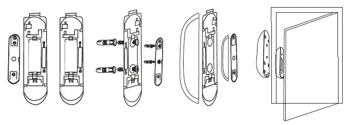
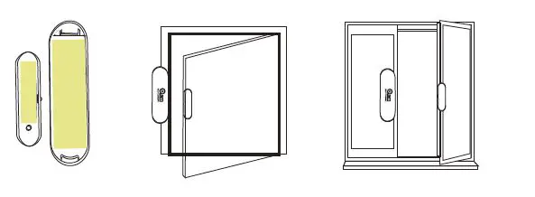
NOTE:” When installing door sensor, door sensor deputy body must be” installed on the bulge side of the door sensor main body.
4.Make sure door sensor is placed in the Z-Wave network range” of gateway.
Inclusion/Exclusion
On factory default the device does not belong to any Z-Wave network. The device needs
to be added to an existing wireless network to communicate with the devices of this network.
This process is called Inclusion.
Devices can also be removed from a network. This process is called Exclusion.
Both processes are initiated by the primary controller of the Z-Wave network. This
controller is turned into exclusion respective inclusion mode. Inclusion and Exclusion is
then performed doing a special manual action right on the device.
Inclusion
Press the button three times within 1.5 second, the device will enter inclusion mode. And the LED will flash on and off alternately five times.
Exclusion
Press the button three times within 1.5 second, the device will enter exclusion mode.
Product Usage
Battery life of door sensor is approximately 1 year. The power” level of battery would be displayed in the gateway. Red icon” means the battery needs replacing, and then mobile app would” receive a message “power level is low, please remember to” replace battery†from gateway. In order to avoid false alarm,” before replacing battery, please disconnect association of door” sensor with other devices.
Note:” Door sensor is powered by battery, and please use battery” in a correct way to avoid exploding.When handling the battery,” refer to environmental law please.
Communication to a Sleeping device (Wakeup)
This device is battery operated and turned into deep sleep state most of the time
to save battery life time. Communication with the device is limited. In order to
communicate with the device, a static controller C is needed in the network.
This controller will maintain a mailbox for the battery operated devices and store
commands that can not be received during deep sleep state. Without such a controller,
communication may become impossible and/or the battery life time is significantly
decreased.
This device will wakeup regularly and announce the wakeup
state by sending out a so called Wakeup Notification. The controller can then
empty the mailbox. Therefore, the device needs to be configured with the desired
wakeup interval and the node ID of the controller. If the device was included by
a static controller this controller will usually perform all necessary
configurations. The wakeup interval is a tradeoff between maximal battery
life time and the desired responses of the device. To wakeup the device please perform
the following action:
Manual Wakeup the Sensor You can press the button once to wake up the device and send wakeup notification to controller. If press successfully, the LED will blink one time.
Quick trouble shooting
Here are a few hints for network installation if things dont work as expected.
- Make sure a device is in factory reset state before including. In doubt exclude before include.
- If inclusion still fails, check if both devices use the same frequency.
- Remove all dead devices from associations. Otherwise you will see severe delays.
- Never use sleeping battery devices without a central controller.
- Dont poll FLIRS devices.
- Make sure to have enough mains powered device to benefit from the meshing
Association – one device controls an other device
Z-Wave devices control other Z-Wave devices. The relationship between one device
controlling another device is called association. In order to control a different
device, the controlling device needs to maintain a list of devices that will receive
controlling commands. These lists are called association groups and they are always
related to certain events (e.g. button pressed, sensor triggers, …). In case
the event happens all devices stored in the respective association group will
receive the same wireless command wireless command, typically a ‘Basic Set’ Command.
Association Groups:
Group NumberMaximum NodesDescription
| 1 | 5 | GROUP 1 is lifeline service that assigned to Sensor (Door/Window detector) status u2013 Open/Close. It enables the sensor to send reports and readings to Z-Wave Controller or Z-Wave Gateway whenever the sensor is triggered. This Group Support:NOTIFICATION_REPORT BATTERY_REPORT SENSOR_BINARY_REPORT DEVICE_RESET_LOCALLY_NOTIFICATION |
| 2 | 5 | GROUP 2 allows for sending control commands to associated devices such as relay module, lighting, etc. This association group is configured through the advanced parameters no. 1 and 2. This Group Support:BASIC_SET. |
| 3 | 5 | GROUP 3 allows for Send Notification to associated devices in this group. This Group Support: NOTIFICATION_REPORT |
| 4 | 5 | GROUP 4 allows for Send Notification to associated devices in this group. This Group Support: SENSOR_BINARY_REPORT |
Configuration Parameters
Z-Wave products are supposed to work out of the box after inclusion, however
certain configuration can adapt the function better to user needs or unlock further
enhanced features.
IMPORTANT: Controllers may only allow configuring
signed values. In order to set values in the range 128 … 255 the value sent in
the application shall be the desired value minus 256. For example: To set a
parameter to 200 it may be needed to set a value of 200 minus 256 = minus 56.
In case of a two byte value the same logic applies: Values greater than 32768 may
needed to be given as negative values too.
Parameter 1: Configuring the OFF Delay
This configuration parameter can be used to adjust the amount” of delay before the OFF command is transmitted.
Size: 2 Byte, Default Value: 0
SettingDescription
| 0 – 65535 | Seconds |
Parameter 2: Basic Set Level
Basic Set Command will be sent where contains a value when” the door/window is opened or closed, Z-Wave controller or z-wave gateway will take it for consideration; for instance, if a lamp” module receives the Basic Set Command of which value is” decisive as to how bright of dim level of lamp module shall be.
Size: 1 Byte, Default Value: 255
SettingDescription
| 0 | Alarm Off |
| 1 – 99 | Alarm cancelling |
| 255 | Alarm On |
Technical Data
| Dimensions | 70 x 20 x 20 mm |
| Weight | 16 gr |
| Hardware Platform | ZM5202 |
| EAN | 6924715900520 |
| IP Class | IP 20 |
| Battery Type | 1 * CR2 |
| Device Type | Notification Sensor |
| Network Operation | Reporting Sleeping Slave |
| Z-Wave Version | 6.51.06 |
| Certification ID | ZC10-16055076 |
| Z-Wave Product Id | 0x0258.0x0003.0x1082 |
| Sensors | Open/Closed (Binary) |
| Color | White |
| Firmware Updatable | Updatable by Manufacturer |
| Frequency | Europe – 868,4 Mhz |
| Maximum transmission power | 5 mW |
Supported Command Classes
- Association Group Information
- Association V2
- Battery
- Configuration
- Device Reset Locally
- Manufacturer Specific
- Notification V4
- Powerlevel
- Sensor Binary V2
- Version V2
- Wake Up V2
- Zwaveplus Info V2
Controlled Command Classes
- Basic
Explanation of Z-Wave specific terms
- Controller — is a Z-Wave device with capabilities to manage the network.
Controllers are typically Gateways,Remote Controls or battery operated wall controllers. - Slave — is a Z-Wave device without capabilities to manage the network.
Slaves can be sensors, actuators and even remote controls. - Primary Controller — is the central organizer of the network. It must be
a controller. There can be only one primary controller in a Z-Wave network. - Inclusion — is the process of adding new Z-Wave devices into a network.
- Exclusion — is the process of removing Z-Wave devices from the network.
- Association — is a control relationship between a controlling device and
a controlled device. - Wakeup Notification — is a special wireless message issued by a Z-Wave
device to announces that is able to communicate. - Node Information Frame — is a special wireless message issued by a
Z-Wave device to announce its capabilities and functions.


 Pst02-5c Manual")


