Neo Electronics Co Limited
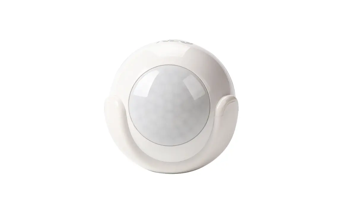
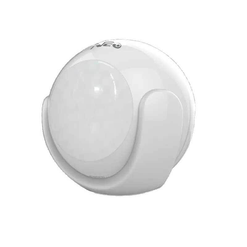
Motion Sensor
SKU: NEOEMS01Z

Quickstart
This is a
Motion Sensor
for
Europe.
To run this device please insert fresh 1 * CR123A batteries.
Please make sure the internal battery is fully charged.
Important safety information
Please read this manual carefully. Failure to follow the recommendations in this manual may be dangerous or may violate the law.
The manufacturer, importer, distributor and seller shall not be liable for any loss or damage resulting from failure to comply with the instructions in this manual or any other material.
Use this equipment only for its intended purpose. Follow the disposal instructions.
Do not dispose of electronic equipment or batteries in a fire or near open heat sources.
What is Z-Wave?
Z-Wave is the international wireless protocol for communication in the Smart Home. This
device is suited for use in the region mentioned in the Quickstart section.

Z-Wave ensures a reliable communication by reconfirming every message (two-way
communication) and every mains powered node can act as a repeater for other nodes
(meshed network) in case the receiver is not in direct wireless range of the
transmitter.
This device and every other certified Z-Wave device can be used together with any other
certified Z-Wave device regardless of brand and origin as long as both are suited for the
same frequency range.
If a device supports secure communication it will communicate with other devices
secure as long as this device provides the same or a higher level of security.
Otherwise it will automatically turn into a lower level of security to maintain
backward compatibility.
For more information about Z-Wave technology, devices, white papers etc. please refer
to www.z-wave.info.
Product Description
Prepare for Installation / Reset
Please read the user manual before installing the product.
In order to include (add) a Z-Wave device to a network it must be in factory default
state. Please make sure to reset the device into factory default. You can do this by
performing an Exclusion operation as described below in the manual. Every Z-Wave
controller is able to perform this operation however it is recommended to use the primary
controller of the previous network to make sure the very device is excluded properly
from this network.
Reset to factory default
This device also allows to be reset without any involvement of a Z-Wave controller. This
procedure should only be used when the primary controller is inoperable.
Safety Warning for Batteries
The product contains batteries. Please remove the batteries when the device is not used.
Do not mix batteries of different charging level or different brands.
Installation
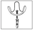
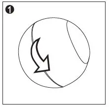
Holder Installation
Fix the holder with” screws and screw” stopper or put the sticker on the bottom of motion sensor then fix it on the wall.
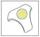
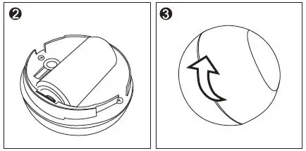
Battery Installation
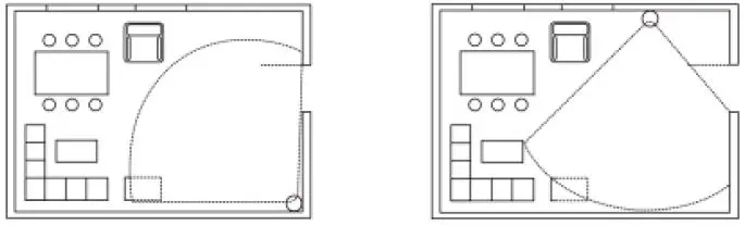
4.Furniture, large bonsai or other spacers shouldn’t be placed” within PIR’s detection area.
Detection Range
Detection range of PIR shown in the following picture
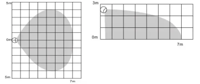
Work schematic diagram of PIR is shown in the following picture
Inclusion/Exclusion
On factory default the device does not belong to any Z-Wave network. The device needs
to be added to an existing wireless network to communicate with the devices of this network.
This process is called Inclusion.
Devices can also be removed from a network. This process is called Exclusion.
Both processes are initiated by the primary controller of the Z-Wave network. This
controller is turned into exclusion respective inclusion mode. Inclusion and Exclusion is
then performed doing a special manual action right on the device.
Inclusion
Press the code button in PIR sensor three times continuously
Exclusion
Press the code button in PIR sensor three times continuously
Product Usage
Battery Usage Tips
Battery life of motion sensor is approximately 1 year. The power” level of battery would be displayed in the gateway. Red icon” means the battery needs replacing, and then mobile app would” receive a message “power level is low, please remember to” replace battery†from gateway. In order to avoid false alarm,” before replacing battery, please disconnect association of” motion sensor with other devices.”
Note: PIR motion sensor is powered by battery, and please use” battery in a correct way to avoid exploding.” When handling the battery, refer to environmental law please.
LED Indicator
Communication to a Sleeping device (Wakeup)
This device is battery operated and turned into deep sleep state most of the time
to save battery life time. Communication with the device is limited. In order to
communicate with the device, a static controller C is needed in the network.
This controller will maintain a mailbox for the battery operated devices and store
commands that can not be received during deep sleep state. Without such a controller,
communication may become impossible and/or the battery life time is significantly
decreased.
This device will wakeup regularly and announce the wakeup
state by sending out a so called Wakeup Notification. The controller can then
empty the mailbox. Therefore, the device needs to be configured with the desired
wakeup interval and the node ID of the controller. If the device was included by
a static controller this controller will usually perform all necessary
configurations. The wakeup interval is a tradeoff between maximal battery
life time and the desired responses of the device. To wakeup the device please perform
the following action:
Quick trouble shooting
Here are a few hints for network installation if things dont work as expected.
- Make sure a device is in factory reset state before including. In doubt exclude before include.
- If inclusion still fails, check if both devices use the same frequency.
- Remove all dead devices from associations. Otherwise you will see severe delays.
- Never use sleeping battery devices without a central controller.
- Dont poll FLIRS devices.
- Make sure to have enough mains powered device to benefit from the meshing
Association – one device controls an other device
Z-Wave devices control other Z-Wave devices. The relationship between one device
controlling another device is called association. In order to control a different
device, the controlling device needs to maintain a list of devices that will receive
controlling commands. These lists are called association groups and they are always
related to certain events (e.g. button pressed, sensor triggers, …). In case
the event happens all devices stored in the respective association group will
receive the same wireless command wireless command, typically a ‘Basic Set’ Command.
Association Groups:
Group NumberMaximum NodesDescription
| 1 | 4 | Lifeline |
| 2 | 4 | Send control commands to associated” devices such as relay module, lighting, etc. |
| 3 | 4 | Send Notification to associated devices in” this group. |
| 4 | 4 | Sending Sensor Binary Report to associated” devices in this group. |
Configuration Parameters
Z-Wave products are supposed to work out of the box after inclusion, however
certain configuration can adapt the function better to user needs or unlock further
enhanced features.
IMPORTANT: Controllers may only allow configuring
signed values. In order to set values in the range 128 … 255 the value sent in
the application shall be the desired value minus 256. For example: To set a
parameter to 200 it may be needed to set a value of 200 minus 256 = minus 56.
In case of a two byte value the same logic applies: Values greater than 32768 may
needed to be given as negative values too.
Parameter 1: Sensitivity Level Setting
This parameter defines the sensitivity of PIR sensor. At the first” time of test, it is recommended to test the sensor with” movements from a farthest end of the coverage area . If” movements cannot be detected sensitively, simply adjust the” sensitivity level by changing this parameter.
Size: 1 Byte, Default Value: 12
SettingDescription
| 8 – 255 | Sensitivity Level Setting. |
Parameter 2: On/Off Duration
This parameter can determine how long the associated devices” should stay ON status. For instance, this parameter is set to” 30(second), PIR sensor will send a BASIC SET Command to an” associated device with value basic set level if PIR sensor is” triggered, and the associated devices will be turned on, and stay” in this status for 30(second) before it is turned off automatically.
Size: 2 Byte, Default Value: 30
SettingDescription
| 5 – 600 | On/Off Duration Setting |
Parameter 3: Basic Set Level
Basic Set Command will be sent where contains a value when” motion sensor is triggered, Z-Wave gateway will take it for” consideration; for instance, if a lamp module is received the” Basic Set Command of which value is decisive as to how bright of” dim level of lamp module shall be.
Size: 1 Byte, Default Value: 99
SettingDescription
| 0 | OFF |
| 1 – 99 | Alarm cancelling or turning a device off |
| 255 | ON |
Parameter 4: PIR Detecting Function Enabled/Disabled
This parameter can enable or disable PIR detector detecting” function.
Size: 1 Byte, Default Value: 255
SettingDescription
| 0 | Disable PIR Detector |
| 255 | Enable PIR Detector |
Parameter 5: Ambient illumination Lux Level
This parameter can be set a lux level value which determines” when light sensor is activated. If the ambient illumination level” falls below this value, and a person moves across or stands” within the detected area , PIR detector will send a Z-Wave ON” command(i.e. BASIC_SET value = parameter 3#) to an” associated device and activate it.
Size: 2 Byte, Default Value: 100
SettingDescription
| 0 – 1000 | LUX |
Parameter 6: Re-trigger Interval Setting
This Parameter can be used to adjust the interval of being retriggered” after PIR sensor has been triggered. This Parameter” value must be less than Parameter 2#.If user set this” parameter to default by Configure CC, the parameter #2 will be” set to default value
Size: 1 Byte, Default Value: 8
SettingDescription
| 1 – 8 | Re-trigger Interval Setting. |
Parameter 7: Light Sensor Polling Interval
This Parameter can be set as interval time for light sensor” measuring ambient illumination level.
Size: 2 Byte, Default Value: 180
SettingDescription
| 60 – 36000 | Light Sensor Polling Interval |
Parameter 8: Lux Level Function Enable
If this parameter is set to ‘1’, and when Lux level is less than the” value defined by parameter #5, PIR sensor will send a” BASIC_SET command frame(i.e. BASIC_SET (value =” parameter 3) to an associated device and activate it. If Lux Level” is greater than the value defined by parameter #5, PIR sensor” will not send a BASIC_SET command frame.
Size: 1 Byte, Default Value: 0
SettingDescription
| 0 | Disable |
| 1 | Enable |
Parameter 9: Ambient illumination Lux Level Report
This parameter defines how much Lux must be changed first,” then PIR sensor will report to z wave gateway.
Size: 1 Byte, Default Value: 100
SettingDescription
| 0 – 255 | Lux Level Report |
Parameter 10: Led Blink Enable
This parameter defines the Led on/off enable. If this parameter” is set to ‘1’, led blink will be enabled, the led will blink once when” motion sensor detect a movement. Otherwise, the led will be” turned off always.
Size: 1 Byte, Default Value: 1
SettingDescription
| 0 | Disable |
| 1 | Enable |
Parameter 99: Ambient light intensity calibration
This parameter defines the calibrated scale for ambient light” intensity. Because the method and position that the sensor is” mounted , and the cover of sensor will bring measurement” error,user can get more real light intensity by this parameter” setting. User should run the steps as blows for calibrating.
Size: 2 Byte, Default Value: 10
SettingDescription
| 1 – 65536 | Ambient light intensity calibration |
Technical Data
| Dimensions | 45 x 45 x 48 mm |
| Weight | 25 gr |
| Hardware Platform | ZM5202 |
| EAN | 6924715900544 |
| IP Class | IP 20 |
| Battery Type | 1 * CR123A |
| Device Type | Motion Sensor |
| Network Operation | Sleeping device |
| Firmware Version | 03.61 |
| Z-Wave Version | 04.05 |
| Z-Wave Product Id | 0x0258.0x0003.0x1083 |
| Frequency | Europe – 868,4 Mhz |
| Maximum transmission power | 5 mW |
Supported Command Classes
- Basic
- Sensor Binary
- Sensor Multilevel
- Association Grp Info
- Device Reset Locally
- Zwaveplus Info
- Configuration
- Alarm
- Manufacturer Specific
- Powerlevel
- Battery
- Wake Up
- Association
- Version
Explanation of Z-Wave specific terms
- Controller — is a Z-Wave device with capabilities to manage the network.
Controllers are typically Gateways,Remote Controls or battery operated wall controllers. - Slave — is a Z-Wave device without capabilities to manage the network.
Slaves can be sensors, actuators and even remote controls. - Primary Controller — is the central organizer of the network. It must be
a controller. There can be only one primary controller in a Z-Wave network. - Inclusion — is the process of adding new Z-Wave devices into a network.
- Exclusion — is the process of removing Z-Wave devices from the network.
- Association — is a control relationship between a controlling device and
a controlled device. - Wakeup Notification — is a special wireless message issued by a Z-Wave
device to announces that is able to communicate. - Node Information Frame — is a special wireless message issued by a
Z-Wave device to announce its capabilities and functions.


