![]()
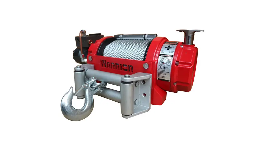
HYDRAULIC WINCH
80RVSHY / 80RVSDY / 10RVSHY / 15RVSHY / 18RVSHY
Assembly & Operating Instructions
INTRODUCTION
We have developed several new series that make up the current product line. Each series in our product line has unique design characteristics; many new patented technologies are integrated into our winches. Your HWP series winch is part of our new product line and has its own salient features: two speeds, single shaft clutch and speed control, and automatic reducer gear engagement. There are three positions of reducer gear engagement, high gear, low gear, and free spool. This new technology has made winches the pinnacle in user convenience and reliability. You will take pride in knowing that your new winch has been designed to work as hard as you and that it will be there when you need it.
Congratulations on your purchase of a highest-class advanced powerful two-speed winch. We design and build winches to strict specifications and with proper use and maintenance should bring you years of satisfying service.
![]() WARNING – Read, study and follow all instructions before operating this device. Failure to heed these instructions may result in personal injury and/or property damage.
WARNING – Read, study and follow all instructions before operating this device. Failure to heed these instructions may result in personal injury and/or property damage.
Your winch can develop tremendous pulling forces and if used unsafely or improperly could result in property damage, serious injury or death. Throughout this manual you will find the following symbols for caution, warning and danger. Pay particular attention to the notes preceded by these symbols as they are written for your safety. Ultimately, safe operation of this device rests with you, the operator.
![]() CAUTION
CAUTION
This indicates a potentially hazardous situation which, if not avoided, may result in minor or moderate injury. This notation is also used to alert you against unsafe practices.![]() WARNING
WARNING
This indicates a potentially hazardous situation which, if not avoided, could result in death or serious injury.
SAFETY WARNINGS AND PRECAUTIONS
![]() WARNING: When using the tool, basic safety precautions should always be followed to reduce the risk of personal injury and damage to the equipment. Read all these instructions before using this tool!
WARNING: When using the tool, basic safety precautions should always be followed to reduce the risk of personal injury and damage to the equipment. Read all these instructions before using this tool!![]() WARNING –Do not use winch to lift (vertically).
WARNING –Do not use winch to lift (vertically).![]() WARNING – Keep children away. Children must never be allowed in the work area Do not let them handle machines, tools, or extension cords.
WARNING – Keep children away. Children must never be allowed in the work area Do not let them handle machines, tools, or extension cords.![]() WARNING – Store idle equipment. When not in use, tools must be stored in a dry location to inhibit rust. Always lock up tools and keep out of reach of children.
WARNING – Store idle equipment. When not in use, tools must be stored in a dry location to inhibit rust. Always lock up tools and keep out of reach of children.![]() WARNING – Dress properly. Do not wear loose clothing or jewelry as they can be caught in moving parts. Protective, electrically non-conductive clothes and non-skid footwear are recommended when working. Wear restrictive hair covering to contain long hair.
WARNING – Dress properly. Do not wear loose clothing or jewelry as they can be caught in moving parts. Protective, electrically non-conductive clothes and non-skid footwear are recommended when working. Wear restrictive hair covering to contain long hair.![]() WARNING – Use eye and ear protection. Always wear impact safety goggles. Wear a full face shield if you are producing metal filings or wood chips. Wear a dust mask or respirator when working around metal, wood, and chemical dusts and mists.
WARNING – Use eye and ear protection. Always wear impact safety goggles. Wear a full face shield if you are producing metal filings or wood chips. Wear a dust mask or respirator when working around metal, wood, and chemical dusts and mists.![]() WARNING – Maintain tools with care. Keep tools sharp and clean for better and safer performance. Follow instructions for lubricating and changing accessories. Inspect tool cords periodically and, if damaged, have them repaired by an authorized technician. The handles must be kept clean, dry, and free from oil and grease at all times.
WARNING – Maintain tools with care. Keep tools sharp and clean for better and safer performance. Follow instructions for lubricating and changing accessories. Inspect tool cords periodically and, if damaged, have them repaired by an authorized technician. The handles must be kept clean, dry, and free from oil and grease at all times.![]() WARNING – Disconnect switch. Unplug switch when not in use.
WARNING – Disconnect switch. Unplug switch when not in use.![]() WARNING – Stay alert. Watch what you are doing, use common sense. Do not operate any tool when you are tired.
WARNING – Stay alert. Watch what you are doing, use common sense. Do not operate any tool when you are tired.![]() WARNING – Check for damaged parts. Before using any tool, any part that appears damaged should be carefully checked to determine that it will operate properly and perform its intended function. Check for alignment and binding of moving parts; any broken parts or mounting fixtures; and any other condition that may affect proper operation. Any part that is damaged should be properly repaired or replaced by a qualified technician. Do not use the tool if any switch does not turn “On” and “Off”
WARNING – Check for damaged parts. Before using any tool, any part that appears damaged should be carefully checked to determine that it will operate properly and perform its intended function. Check for alignment and binding of moving parts; any broken parts or mounting fixtures; and any other condition that may affect proper operation. Any part that is damaged should be properly repaired or replaced by a qualified technician. Do not use the tool if any switch does not turn “On” and “Off”
properly.![]() WARNING – Replacement parts and accessories. When servicing, use only identical replacement parts. Use of any other parts will void the warranty. Only use accessories intended for use this tool.
WARNING – Replacement parts and accessories. When servicing, use only identical replacement parts. Use of any other parts will void the warranty. Only use accessories intended for use this tool.![]() WARNING – Do not operate tool if under the influence of alcohol or drugs. Read warning labels on prescription to determine if your judgment or reflexes are impaired while taking drugs. If there is any doubt, do not operate the tool.
WARNING – Do not operate tool if under the influence of alcohol or drugs. Read warning labels on prescription to determine if your judgment or reflexes are impaired while taking drugs. If there is any doubt, do not operate the tool.
WINCH WARNINGS AND PRECAUTIONS
![]() WARNING – Keep hands and body away from Fairlead (cable intake slot) when operating.
WARNING – Keep hands and body away from Fairlead (cable intake slot) when operating.![]() WARNING – Secure vehicle in position before using winch.
WARNING – Secure vehicle in position before using winch.![]() WARNING – Be certain winch is properly bolted to a structure (or vehicle) that can hold the winch load.
WARNING – Be certain winch is properly bolted to a structure (or vehicle) that can hold the winch load.![]() WARNING – Do not use inappropriate attachments to extend the length of the winch cable.
WARNING – Do not use inappropriate attachments to extend the length of the winch cable.![]() WARNING – Never lift people or hoist loads over people.
WARNING – Never lift people or hoist loads over people.![]() WARNING – Never come in between the winch and the load when operating.
WARNING – Never come in between the winch and the load when operating.![]() WARNING – Do not apply load to winch when cable is fully extended. Keep at least 5 full turns of cable on the spool.
WARNING – Do not apply load to winch when cable is fully extended. Keep at least 5 full turns of cable on the spool.![]() WARNING – After moving an item with the winch, secure the item. Do not rely on the winch to hold it for an extended period.
WARNING – After moving an item with the winch, secure the item. Do not rely on the winch to hold it for an extended period.![]() WARNING – Examine winch before using. Components may be affected by exposure to chemicals, salts, and rust.
WARNING – Examine winch before using. Components may be affected by exposure to chemicals, salts, and rust.![]() WARNING – Never operate winch if cable shows any signs of weakening, such as knotting or kinking.
WARNING – Never operate winch if cable shows any signs of weakening, such as knotting or kinking.![]() WARNING – Do not cross over or under cable when the winch is under load.
WARNING – Do not cross over or under cable when the winch is under load.![]() WARNING – Do not move your vehicle with the cable extended and attached to the load. You could easily exceed the winch rating and snap the cable.
WARNING – Do not move your vehicle with the cable extended and attached to the load. You could easily exceed the winch rating and snap the cable.![]() WARNING – Use gloves while handling cable.
WARNING – Use gloves while handling cable.![]() WARNING – When the vehicle is parked on an incline you should use wheel chocks.
WARNING – When the vehicle is parked on an incline you should use wheel chocks.![]() WARNING – Re-spool cable properly avoiding cable misalignment.
WARNING – Re-spool cable properly avoiding cable misalignment.![]() WARNING – The winch cable must be wound onto the drum under a load of at least 10% of the rated line pull or the outer wraps will draw into inner wraps and damage the winch cable
WARNING – The winch cable must be wound onto the drum under a load of at least 10% of the rated line pull or the outer wraps will draw into inner wraps and damage the winch cable![]() WARNING – Before operating the winch under load you should check the proper function of the winch by engaging and disengaging the clutch, by operating the directional controls, and operating the speed controls. This will ensure that the winch is working properly and will help prevent unintended damage and injury. Cycling the winch prior to loading will also ensure the gears are properly aligned.
WARNING – Before operating the winch under load you should check the proper function of the winch by engaging and disengaging the clutch, by operating the directional controls, and operating the speed controls. This will ensure that the winch is working properly and will help prevent unintended damage and injury. Cycling the winch prior to loading will also ensure the gears are properly aligned.
UNPACKING
When unpacking, check to make sure all parts are included. Refer to Assembly Drawings and Parts List (both with the like item numbers) at the end of this manual.
INSTALLATION
1. Your winch is designed with a bolt pattern that is standard in this class of winch. Many winch mounting kits are available that utilize this bolt pattern for the most popular vehicle and mounting channels. If you cannot find a kit locally, contact us and we will provide you with the name of a dealer near you. If you will utilize the mounting channel you must ensure that it is mounted on a flat surface so that the three major sections (motor, drum and gear housing) are properly aligned. Proper alignment of the winch will allow even distribution of the full rated load.
2. Mount winch to the vehicle using high strength cap screw. It should be aligned and secured to a solid part of the vehicle (front or rear) where the full rated load will be evenly distributed.
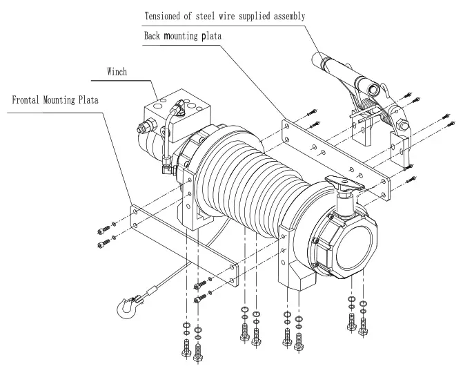
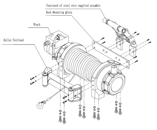
3. Please refer to the installation illustration.
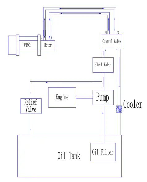
Working hydraulic principle chart and installation illustration:
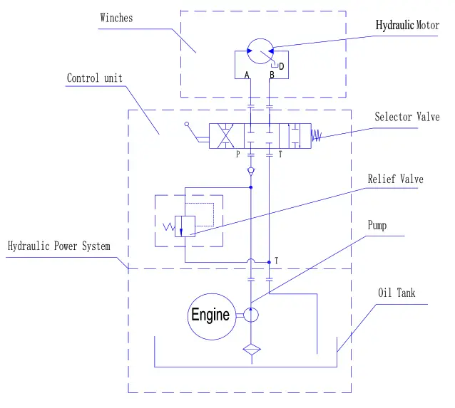
Below is an installation illustration of winch:
Below is an installation illustration with roller fairlead of winch:
![]() Caution:
Caution:
The hydraulic system needs a relief valve to ensure the system safety. The absence of such a valve could cause serious injury and damage the winch.
Winch battery cables should be placed so that there is a small amount of slack in the cable.
If you are using a heat exchanger with your application to cool the hydraulic fluid you should refer to the illustration about mounting. You should check the hydraulic fluid level and replace any that may have seeped out. The hydraulic system should be purged at this time. Listed below are the directions on how to purge the hydraulic system.
1) Start the engine.
2) Power the winch to draw out about 5 feet of cable.
3) Shut down the engine.
4) Check the fluid level and fill as needed.
5) Repeat steps 1 through 4 as necessary.
6) Start the engine.
7) Move the cable into the desired position.
8) Turn the wheels on the vehicle from the right lock to the left lock positions five times to help bleed the hydraulic system.
9) If the hand control unit is working backwards, simple exchange the brown and the white wire connections within the valve. Test the winch for proper operation. Refer to the section below.
OPERATION
![]() WARNING
WARNING
1 Make sure clutch is totally engaged before starting any winch operation;
2 Stay clear and away from raised loads;
3 Stay clear of cable while pulling do not try to guide cable;
4 A min. of 5 wraps of cable around the drum barrel.
General information:
Winch’s standard equipment contain gear reducer、drum、hydraulic motor, solenoid valve、switch assembly、female connector and plumbing fittings. The winch obtains its pressure from the vehicle’s existing power steering pump or other hydraulic power. The winch is totally sealed, can be used underwater. There are several other ways to supply power to the winch. The first way is to use an individual pump for engineering use. The second way is to provide the winch’s hydraulic pressure is with the vehicle’s exiting power steering pump (See Installation Instructions).
① Use a suitable individual pump, which doesn’t have an oil pressure relief valve. It will supply pressure for both the steering box and the winch.
② Use a combined pump with an integrated oil valve. The oil valve will supply two kinds of flow based on the difference in demand. One type of flow will be constant and should be used with the steering system. The other will provide higher pressure and is for engineering use.
![]() Caution:
Caution:
The hydraulic system needs a relief valve to make sure the system is safe; If there is not relief valve in the system; it would be serious danger and the system can’t operation. If your winch drived by an existing hydraulic power system, the relief valve is also existing.
Winch working demonstration:
1. Disengage the clutch by turning the clutch to the “CLUTCH OUT” position.
2. Grab the cable assembly and pull the cable to the desired length, then attach to item being pulled.
Caution: Always leave at least five turns of cable on the drum; Review Winch Safety Warnings and Precautions on page 2、3 before continuing.
3. Reengage the clutch by turning the clutch assembly to the “CLUTCH IN” position as needed.
4. Test-run winch in both directions. Turn the winch in each direction for about one or two seconds meantime make the clutch totally engaged automatically.
5. While standing aside of the tow path, hold and operate the switch assembly supplied by your choice. Wait until the motor stops before reversing directions.
WINCH ACCESSORIES YOU WILL NEED
NOT INCLUDED WITH YOUR WINCH
Gloves – For handling the wire rope and hook strap.
Anchor Strap/Chain – Tree saver anchor straps are made of high-quality nylon with high tensile strengths up to 15000lbs.
Heavy Blanket – place on the cable to absorb energy should the wire rope break.
RIGGING TECHNIQUES
Self-Recovery
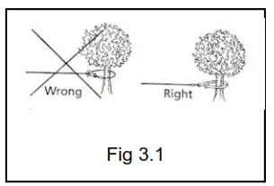
Locate a suitable anchor such as a strong tree trunk or boulder. Always use a sling as an anchor point.![]() CAUTION Do not attach the clevis hook back onto the cable as this could cause damage to the cable.As shown in Fig 3.1
CAUTION Do not attach the clevis hook back onto the cable as this could cause damage to the cable.As shown in Fig 3.1
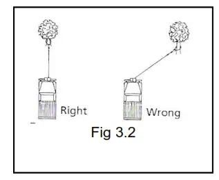
![]() CAUTION Do not winch from an acute angle as the wire rope will pile up on one side of the drum causing damage to wire rope and the winch. Fig 3.2
CAUTION Do not winch from an acute angle as the wire rope will pile up on one side of the drum causing damage to wire rope and the winch. Fig 3.2
Short pulls from an angle can be used to straighten the vehicle. Long pulls should be done with the wire rope at a 90° angle to the winch/vehicle.
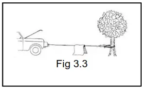
When pulling a heavy load, place a blanket or jacket over the wire rope five or six feet from the hook. In the event of a broken cable it will dampen the snapback. For additional protection open the hood of the vehicle as shown in Fig 3.3
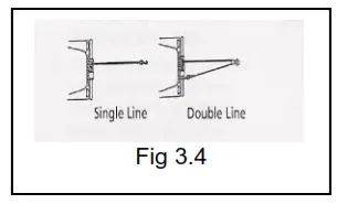
For pulls over 70% rated line pull, we recommend the use of the snatch block/pulley block to double line the wire rope. Fig 3.4 This reduces the load on the winch and the strain on the rope by up to 50% depending on the included angle.
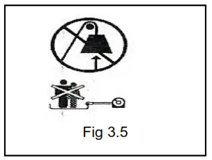
WARNING – Never use your winch for overhead hoisting or for lifting people or moving people.
LUBRICATION
1. All moving parts within the Winch having been Lubricated using high-temperature lithium grease at the factory. No internal lubrication is required.
2. Lubricate Cable Assembly periodically using a light penetrating oil.
CABLE ASSEMBLY REPLACEMENT
If the wire rope has become worn or is beginning to show signs of strands breaking, it must be replaced before being used again.
1. Turning clutch to the “CLUTCH OUT” position.
2. Extend cable assembly to its full length. Note how the existing cable is connected to the drum.
3. Remove old cable assembly and attach new one as the ld cable connected to the drum. Insert the end of the new rope and secure the screw being tightly screwed
4. Turning clutch to the “CLUTCH IN” position.
5. Retract cable assembly onto drum, first five wraps being careful not to allow kinking, then winch cable must be wound onto the drum under a load of at least 10% rated line pull.![]() WARNING – Only replace the wire rope with the identical replacement part recommended by the manufacturer.
WARNING – Only replace the wire rope with the identical replacement part recommended by the manufacturer.
TROUBLESHOOTING
| SYMPTOM | POSSIBLE CAUSE | SUGGESTED ACTION |
| Winch does not turn . | -Insufficiently hydraulic system pressure. -Improper connections of hydraulic system, no oil into motor. | -Check relief valve regulate pressure. -Check all the plumbing fixtures according to the working principle chart. -Defective directional control valve. |
| Motor runs but Cable drum does not turn | – The clutch is Not engaged | -Turn the clutch to the high or lows peed position. If problem still persists, a qualified technician needed to check and repair. |
| Winch drum runs slowly or without normal power. | -Insufficient pressure or oil flow -Insufficient fluid in the system – Wrong winch working and nd motor. | -Bump is not suitable or defective. Change a new one or a suitable one -Check fluid level. Add fluid until full. -Change the connection of balance valve |
| Winch cannot spool off wire rope with load smoothly. | -Wrong winch working direction. | -Change the connection of balance valve and motor. |
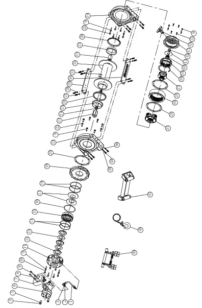
WINCH ASSEMBLY DRAWING
(80RVSHY/80RVSDY/10RVSHY)
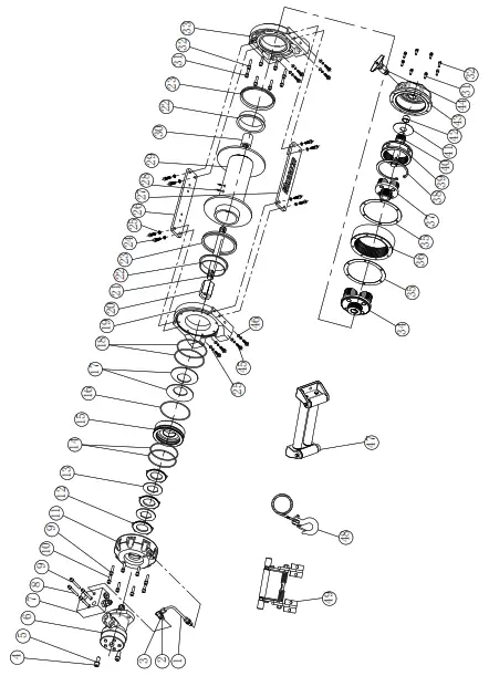
WINCH PARTS LIST
(80RVSHY/80RVSDY/10RVSHY)
| No. | Part # | OlY | Desaiplion | Remark |
| 1 | HV1000001 | 1 | Figh-ccessure oil tube | |
| 2 | HV1000002 | 2 | Oil connection | |
| 3 | HV1000003 | 2 | Combination Washer 14 | |
| 4 | HV1000004 | 2 | Cap Screw M12 x 30 | |
| 5 | HV1000005 | 2 | Lock Washer 012 | |
| 6 | HV1000100-1 | 1 | Hydraulic Motor | used MCORVSHYOORVSDY |
| HV1000100-2 | 1 | Hydraulic Motor | Used in 10FIVSHY | |
| 7 | HV10000013 | 1 | Blanced valve | |
| 8 | HV1000007 | 4 | Cap Screw PA8 x 55 | |
| 9 | HV1000008 | 12 | Lock Washer 08 | |
| 10 | HV1000009 | 8 | Screw M8 x 30 | |
| 11 | HV1000010 | 1 | Brake slants | |
| 12 | HV1000011 | 3 | Brake block | |
| 13 | HV1000012 | 2 | Friction plate | |
| 14 | HV1000013 | 2 | 0-ring seal 100’3.55 | |
| 15 | HV1000014 | 1 | Piston | |
| 18 | HV1000015 | 1 | 0-ring seal 140’2.85 | |
| 17 | HV1000016 | 2 | Disk wring | |
| 18 | HV1000017 | 2 | O-ring seal 118’3.55 | |
| 19 | HV1000018 | 1 | Motor bracket | |
| 20 | HV1000019 | 1 | Coupling | |
| 21 | HV1000020-1 | 1 | Transmission shaft | 1.;:ec n 07RWMY IORVSHY |
| HV1000020-2 | 1 | Transmission shaft | Used S. 8ORVSDY | |
| 22 | HV1000021 | 2 | Bearing bush | |
| 23 | HV1000022 | 2 | Rig Seals | |
| 24 | HV1000023 | 8 | ScrewM10 x 25 | |
| 25 | HV1000024 | 16 | Lock Washer 010 | |
| 213 | HV1000025-1 | 1 | Stand bar ( b ) | usedinconvsmy IORVSHY |
| HV1000025-2 | 1 | Stand bar ( b ) | Used in 80FIVSDY | |
| 27 | HV10000213-1 | 1 | Staal bar ( a ) | Used In OORVSHY IORVffire |
| HV1000026-2 | 1 | Staal bar ( a ) | Used in 80FIVSDY | |
| 28 | HV1000027 | 2 | Screw M8 x 15 | |
| 29 | HV1000200-1 | 1 | Dorn Assembly | Use* in CIORVSHY IORVI3HY |
| HV1000200-2 | 1 | Drum Assembly | Used in801111SW | |
| 30 | HV1000028 | I | C0-0119 I | |
| 31 | HV1000029 | 16 | Cap Screw MO x 20 | |
| 32 | HV11:100030 | 16 | Lock Washer 443 | |
| 33 | HV1000031 | 1 | End Beari-ig | |
| 34 | HV1000300 | 1 | Gear Carrier Assembly (Output, | |
| 35 | HV1000032 | 2 | Gasket | |
| 38 | HV1000033 | 1 | Gear-Rng Φ Outputs | |
| 37 | HV1000400 | 1 | Gear Carrier Assembly I haul/ | |
| 38 | HV1000034 | 1 | Clain for hole 0125 | |
| 39 | HV1000035 | 1 | Gear-Rig I Input/ | |
| 40 | HV1000038 | 1 | Gear—Input Sun | |
| 41 | HV1000037 | 1 | Trust Washer | |
| 42 | HV1000038 | 1 | Me sleeve | |
| 43 | HV1000039 | 1 | Cover-Gear Housiog | |
| 44 | HV1000500 | 1 | Clutch Assembly | |
| 45 | HV1000040 | 8 | Screw M10 x 35 | |
| 46 | HV1000041 | 8 | Think Flat Washer 010 | |
| 47 | HV1000600-1 | 1 | Roller Fairlead | Used in 8ORVSHY lORVSHY |
| HV1000600-2 | 1 | Roller Fairlead | Used in 8ORVSDY | |
| 48 | HV1000700-1 | 1 | Cable Assembly | Used in 8ORVSHY 8ORVSDY |
| HV1000700-2 | 1 | Cable Assembly | Used in 1ORVSHY | |
| 49 | HV1000800-1 | 1 | Tensioned Of Steel Wire Supplied Assembly | Used in 8ORVSHY lORVSHY |
| HV1000800-2 | 1 | Tensioned Of Steel Wire Supplied Assembly | Used in 8ORVSDY |
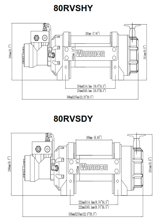
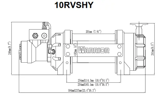
OUTLINE DIMENSIONAL DRAWING
WINCH ASSEMBLY DRAWING (15RVSHY/18RVSHY)
WINCH PARTS LIST (15RVSHY/18RVSHY)
| No. | Part # | Qty | Description | Remark |
| 1 | HV1500001 | 1 | High-pressure oil tube | |
| 2 | HV1500002 | 2 | Oil connection Oil | |
| 3 | HV1500003 | 2 | Combination Washer 14 | |
| 4 | HV1500004 | 2 | Cap Screw M12 x 30 | |
| 5 | HV1500005 | 2 | Lock Washer Φ12 | |
| 6 | HV1500100-1 | 1 | Hydraulic Motor | Used in 15RVSHY |
| HV1500100-2 | 1 | Hydraulic Motor | Used in 18RVSHY | |
| 7 | HV1500006 | 1 | Balanced valve | |
| 8 | HV1500007 | 4 | Cap Screw M8 x 55 | |
| 9 | HV1500008 | 36 | Lock Washer Φ8 | |
| 10 | HV1500009 | 8 | Screw M8 x 30 | |
| 11 | HV1500010 | 1 | Brake stents | |
| 12 | HV1500011 | 3 | Brake block | |
| 13 | HV1500012 | 2 | Friction plate | |
| 14 | HV1500013 | 2 | 0-ring seal 100’3.55 | |
| 15 | HV1500014 | 1 | Piston | |
| 16 | HV1500015 | 1 | 0-ring seal 140’2.65 | |
| 17 | HV1500016 | 2 | Disk spring | |
| 18 | HV1500017 | 2 | 0-ring seal 118’3.55 | |
| 19 | HV1500018 | 1 | Motor mounting plate | |
| 20 | HV1500019 | 3 | Gasket | |
| 21 | HV 1500020 | 1 | Motor bracket | |
| 22 | HV1500021 | 24 | Screw M8 x 25 | |
| 23 | HV1500022 | 1 | Coupling | |
| 24 | HV1500023 | 1 | Transmission shaft | |
| 25 | HV1500024 | 2 | Bearing bush | |
| 26 | HV1500025 | 2 | Ring Seals | |
| 27 | HV1500026 | 8 | Screw M10 x 25 | |
| 28 | HV1500027 | 16 | Lock Washer Φ10 | |
| 29 | HV1500028 | 1 | Stand bar(a) | |
| 30 | HV1500029 | 1 | Stand bar(b) | |
| 31 | HV1500030 | 2 | Screw M8 x 15 | |
| 32 | HV1500200-1 | 1 | Drum Assembly | Used in 15RVSHY |
| HV1500200-2 | 1 | Drum Assembly | Used in 18RVSHY | |
| 33 | HV1500031 | 1 | Coupling I | |
| 34 | HV1500032 | 1 | End Bearing | |
| 35 | HV1500300 | 1 | Gear Carrier Assembly (Output) | |
| 36 | HV1500033 | 1 | Gear-Ring (Output) | |
| 37 | HV1500400 | 1 | Gear Carrier Assembly (Input) | |
| 38 | HV1500034 | 1 | Credit for hole Φ125 | |
| 39 | HV1500035 | 1 | Gear-Ring ( Input ) | |
| 40 | HV1500036 | 1 | Gear—Input Sun | |
| 41 | HV1500037 | 1 | Trust Washer | |
| 42 | HV1500038 | 1 | Axle sleeve | |
| 43 | HV 1500039 | 1 | Cover-Gear Housing | |
| 44 | HV1500500 | 1 | Clutch Assembly | |
| 45 | HV1500040 | 8 | Screw M10 x 35 | |
| 46 | HV1500041 | 8 | Think Flat Washer Φ10 |
| 47 | HV1500600 | 1 | Roller Fairlead | |
| 48 | HV1500700-1 | 1 | Cable Assembly | Used in 15RVSHY |
| HV1500700-2 | 1 | Cable Assembly | Used in 18RVSHY | |
| 49 | HV1500800 | 1 | Tensioned Of Steel Wire Supplied Assembly |
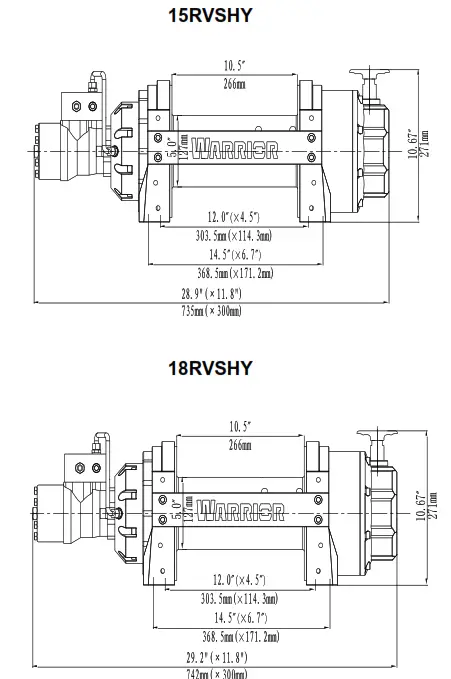
OUTLINE DIMENSIONAL DRAWING
SPECIFICATION(80RVSHY)
| Rated line pull | 8000 lbs (3629 kgs) |
| Motor displacement | 80m1/r |
| Oil flow | 5-60L/min |
| Pressure | 12Mpa |
| Gear reduction ratio | 17.6:1 |
| Cable (Dia. x L) | Ø3/8″x 98.4′ (Ø9.2mm x 30.0m) |
| Drum size(Dia. x L) | Ø4.0 “x 7.91” (Ø102mm x 201 mm) |
| Mounting bolt pattern | 10″x 4.5 ” (254mm x 114.3mm) ; 10″x 6.5″ (254mm x 165.1mm) 8-M10 |
| Overall dimensions (LxWxH) | 23.23″ x 9.3″ x 9.5″ 590mm x 237mm x 241 mm |
| Net weight lbs(kg) | 108 49 |
Pull, Speed, Pressure, Flow (First layer)
| Line pull lbs (kgs) | Pressure Mpa(Psi) | Flow G/min (L/min) | Line speed ft/min(m/min) |
| 0 | 2.0(290.1) | 1.3(5) | 3.2(1.0) |
| 4000(1814) | 5.0(725.2) | 5.3(20) | 10.8(3.3) |
| 6000(2722) | 8.0(1160.3) | 10.5(40) | 23.9(7.3) |
| 8000(3629) | 12.0(1740.4) | 15.8(60) | 37.7(11.5) |
Line Pull And Rope Capacity Inlayer
| Layer of wire rope | Rated line pull lbs(kgs) | Total rope on drum ft (m) |
| 1 | 8000(3629) | 21.3(6.5) |
| 2 | 6864(3113) | 49.2(15.0) |
| 3 | 6010(2726) | 80.4(24.5) |
| 4 | 5345(2424) | 98.4(30.0) |
SPECIFICATION(80RVSDY)
| Rated line pull | 8000 lbs (3629 kgs) |
| Motor displacement | 80m1/r |
| Oil flow | 5 -60L/min |
| Pressure | 12Mpa |
| Gear reduction ratio | 17.6:1 |
| Cable (Dia. x L) | Ø3/8″ x 98.4′ (Ø9.2mm x 30.0m) |
| Drum size(Dia. x L) | Ø4.0 ” x 6.65″ (Ø102mm x 169mm) |
| Mounting bolt pattern | 8.74″ x 4.5 ” (222mm x 114.3mm) : 8.74″ x 6.5″ (222mm x 165.1mm) 8-M10 |
| Overall dimensions (LxWx H) | 22.0″ x 9.3″ x 9.5″ 558mm x 237mm x 241mm |
| Net weight lbs(kg) | 105 47.6 |
Pull , Speed, Pressure, Flow (First layer)
| Line pull lbs (kgs) | Pressure Mpa(Psi) | Flow G/min (L/min) | Line speed ftlmin(m/min) |
| 0 | 2.0(290.1) | 1.3(5) | 3.2(1.0) |
| 4000(1814) | 5.0(725.2) | 5.3(20) | 10.8(3.3) |
| 6000(2722) | 8.0(1160.3) | 10.5(40) | 23.9(7.3) |
| 8000(3629) | 12.0(1740.4) | 15.8(60) | 37.7(11.5) |
Line Pull And Rope Capacity Inlayer
| Layer of wire rope | Rated line pull lbs(kgs) | Total rope on drum ft (m) |
| 1 | 8000(3629) | 18.4(5.6) |
| 2 | 6864(3113) | 42.3(12.9) |
| 3 | 6010(2726) | 69.5(21.2) |
| 4 | 5345(2424) | 98.4(30.0) |
SPECIFICATION(10RVSHY)
| Rated line pull | 10000 lbs (4536 kgs) |
| Motor displacement | 100mUr |
| Oil flow | 5-60L/min |
| Pressure | 15Mpa |
| Gear reduction ratio | 17.6:1 |
| Cable (Dia. X L) | Ø13/32-X98.4′ (Ø10.2mm X 30.0m) |
| Drum sin(D18.X L) | Ø4.0′ X 7.91″ Ø102mm X 201mm) |
| Mounting bolt pattern | 10″X 4.5 – (254mm X 114.3mm) 10″ X6.5′ (254mm X 165.1 mm) 8-M10 |
| Overall dimensions (LXWXH) | 23.4’X9.3″X9.5a 594mm X 237mm X 241mm |
| Net weight lbs(kg) | 110 49.9 |
Pull, Speed, Pressure, Flow (First layer)
| Line pull lbs (kgs) | Pressure Mpa(PsI) | Flow G/min (Urnin) | Line speed fUmin(rn/min) |
| 0 | 3.0(435.1) | 1.3(5) | 3.0(0.9) |
| 4000(1814) | 6.8(986.2) | 2.6(10) | 5.9(1.8) |
| 6000(2722) | 9.2(1334.3) | 5.2(20) | 11.8 (3.6) |
| 8000(3629) | 12.0(1740.4) | 10.4(40) | 23.6(7.2) |
| 10000(4536) | 15.0(2175) | 15.6(60) | 36.1(11) |
Line Pull And Rope Capacity Inlayer
| Layer of wire rope | Rated line pull lbs(kgs) | Total rope on drum ft (m) |
| 1 | 10000(4536) | 23.0(7.0) |
| 2 | 7355(3336) | 49.2(15.0) |
| 3 | 6780(3075) | 78.7(24.0) |
| 4 | 5711(2591) | 98.4(30.0) |
SPECIFICATION(15RVSHY)
| Rated line pull | 15000 lbs (6804 kgs) |
| Motor displacement | 160m1/r |
| Oil flow | 5 – 60Umin |
| Pressure | 17.5Mpa |
| Gear reduction ratio | 17.3:1 |
| Cable (Dia. X L) | Ø15/32″ x 98.4′ (Ø12mm X 30.0m) |
| Drum size(Dia. X L) | Ø5.0 “x 10.5′ (Ø127mm X 266mm) |
| Mounting bolt pattern | 12.0 “X 4.5 – (303.5mm X 114.3mm) : 14.5 ” X 6.7″ (368.5mm X 171.2mm) 8-M12 |
| Overall dimensions (LxWXH) | 28.9″ X 11.8″ X 10.9″ 735mm X 300mm X 277mm |
| Net weight lbs(kg) | 184.3 83.6 |
Pull , Speed, Pressure, Flow (First layer)
| Line pull lbs (kgs) | Pressure Mpa(Psi) | Flow G/min (Umin) | Line speed ft/min(m/min) |
| 0 | 2.0(290) | 2.6(10) | 4.2(1.3) |
| 8000(3629) | 9.2(1337) | 5.2(20) | 8.5(2.6) |
| 10000(4536) | 11.5(1627) | 7.9(30) | 12.4 (3.8) |
| 12000(5448) | 14.0(2030) | 10.4(40) | 16.7(5.1) |
| 15000(6810) | 17.5(2537) | 15.6(60) | 23(7) |
Line Pull And Rope Capacity Inlayer
| Layer of wire rope | Rated line pull lbs(kgs) | Total rope on drum ft (m) |
| 1 | 15000(6804) | 29.5(9.0) |
| 2 | 12791(5807) | 65.6(20.0) |
| 3 | 11150(5062) | 98.4(30.0) |
SPECIFICATION(18RVSHY)
| Rated line pull | 18000 lbs (8165 kgs) |
| Motor displacement | 200mVr |
| Oil flow | 5 – 60Umin |
| Pressure | 16Mpa |
| Gear reduction ratio | 17.3:1 |
| Cable (Dia. X L) | Ø9/16″ X 91.8′ (Ø14mm X 28.0m) |
| Drum size(Dia. X L) | Ø5.0 “X 10.5” (Ø127mm X 266mm) |
| Mounting bolt pattern | 12.0 “X 4.5- (303.5mm X 114.3mm) : 14.5 ” X 6.7″ (368.5mm X 171.2mm) 8-M12 |
| Overall dimensions (LXWXH) | 29.2″ X11.8″ X 10.9″ 742mm x 300mm X 277mm |
| Net weight lbs(kg) | 190 86.2 |
Pull , Speed, Pressure, Flow (First layer)
| Line pull lbs (kgs) | Pressure Mpa(Psi) | Flow G/min (Umin) | Line speed ft/min(m/min) |
| 0 | 2.0(290.1) | 2.6(10) | 4.6(1.4) |
| 8000(3629) | 5.8(841.2) | 5.2(20) | 6.6(2.0) |
| 12000(5448) | 9.2(1334.3) | 10.4(40) | 13.1(4.0) |
| 15000(6810) | 12.0(1740.5) | 13.2(50) | 17.4(5.3) |
| 18000(8165) | 16.0(2320.6) | 15.6(60) | 24(7.3) |
Line Pull And Rope Capacity Inlayer
| Layer of wire rope | Rated line pull lbs(kgs) | Total rope on drum ft (m) |
| 1 | 18000(8165) | 25.9(7.9) |
| 2 | 15017(6811) | 58.7(17.9) |
| 3 | 12882(5843) | 91.8(28.0) |


