WESCO 273515 Hand Winch Lifter
GENERAL INFORMATION
NOTE: All of the information reported herein is based on data available at the moment of printing. We reserve the right to modify our own products at any moment without notice and liability in any sanctions. So, it is suggested to always verify possible updates and changes.
DESCRIPTION
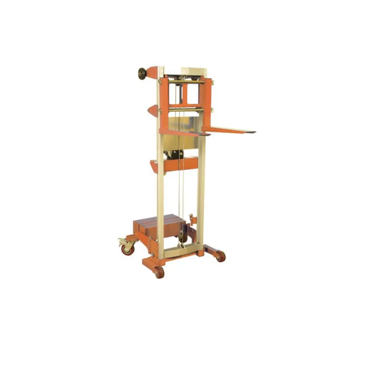
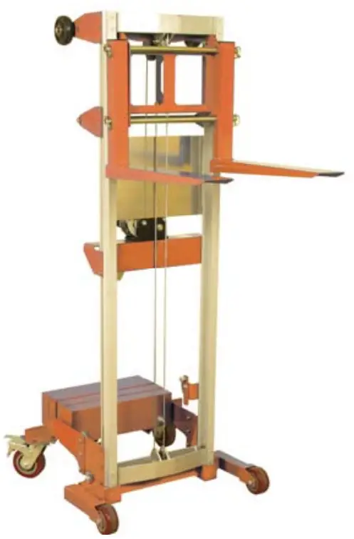
Thank you for purchasing a Wesco Manual Winch Lift. This unit is designed to lift material to and from shelves, move office equipment and install ceiling and wall appliances on level surfaces, including workshops, warehouses, stockrooms, receiving departments. It is perfect for when aisles and congested areas prevent the use of larger equipment. It is constructed of durable steel with a lightweight aluminum frame. The forks can be inverted to provide two different lift heights. It is operated by a hand-crank winch.
SPECIFICATIONS
| Part Number | Model # | Load Cap (lbs) | Lifting Height (in.) | Overall Dimensions (in.) | Load Center (in) | |||
| Forks Up | Forks Down | L | W | H | ||||
| 273510 | HWLFX-4 | 400 | 120.5 | 99 | 34-1/2 | 24 | 67 | 10 |
| 273511 | HWLFX-5 | 500 | 71 | 48.5 | 34-1/2 | 24 | 67 | 10 |
| 273512 | HWLSD-3.5 | 350 | 142 | 120 | 43 | 29 | 79-3/4 | 10 |
| 273513 | HWLSD-4 | 400 | 120.5 | 99 | 43 | 29 | 67 | 10 |
| 273514 | HWLSD-5 | 500 | 71 | 48.5 | 43 | 29 | 67 | 10 |
| 273515 | HWLCB-3.5 | 350 | 140 | 118.5 | 46 | 29 | 79-3/4 | 10 |
| 273516 | HWLCB-4 | 400 | 120.5 | 99 | 46 | 29 | 67 | 10 |
| 273517 | HWLCB-5 | 500 | 71 | 48.5 | 46 | 29 | 67 | 10 |
Materials and specifications are subject to change without notice.
PRE-OPERATION
Inspection
A visual inspection should be performed by the operator prior to each work shift. This inspection is designed to discover if anything is apparently wrong with a machine before the operator test it.
Inspect the machine for modifications, damage or loose or missing parts. A damaged or modified machine must never be used. If damage or any variation from factory delivered condition is discovered, the machine must be tagged and removed from service. Repairs to the machine may only be made by a qualified service technician, according to the manufacturer’s specifications. After repairs are completed, the operator must perform a per-operation inspection again before testing the machine functions.
Check the following components or areas for damage, modifications and improperly installed or missing parts:
- Winch and related components
- Base components
- Cable Anchor
- Cable (frays, abrasions)
- Legs
- Cable and pulleys
- Brake system (if equipped)
- Roller wheels
- Carriage hold-down assembly
- Wheels and casters
- Inner and outer frames
- Forks – Glide buttons
Check the entire machine for:
- Dents or damage
- Corrosion or oxidation
- Cracks in welds or structural components
ASSEMBLY
step 1: Attach the 5 inch swivel castors to the counterweight support weldment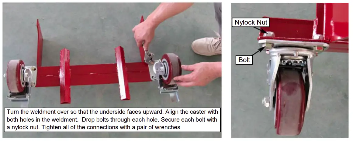
step 2: Attach the weldment to the main assembly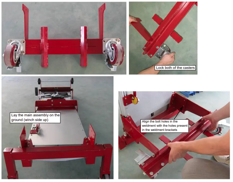
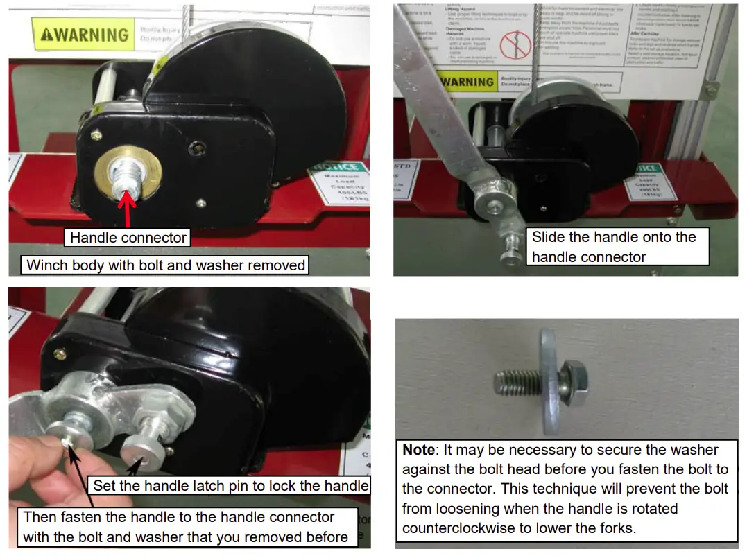
Step 3: Lift the assembly to the upright position (photo A), lock the brakes (photo B) and fasten the winch handle to the winch body.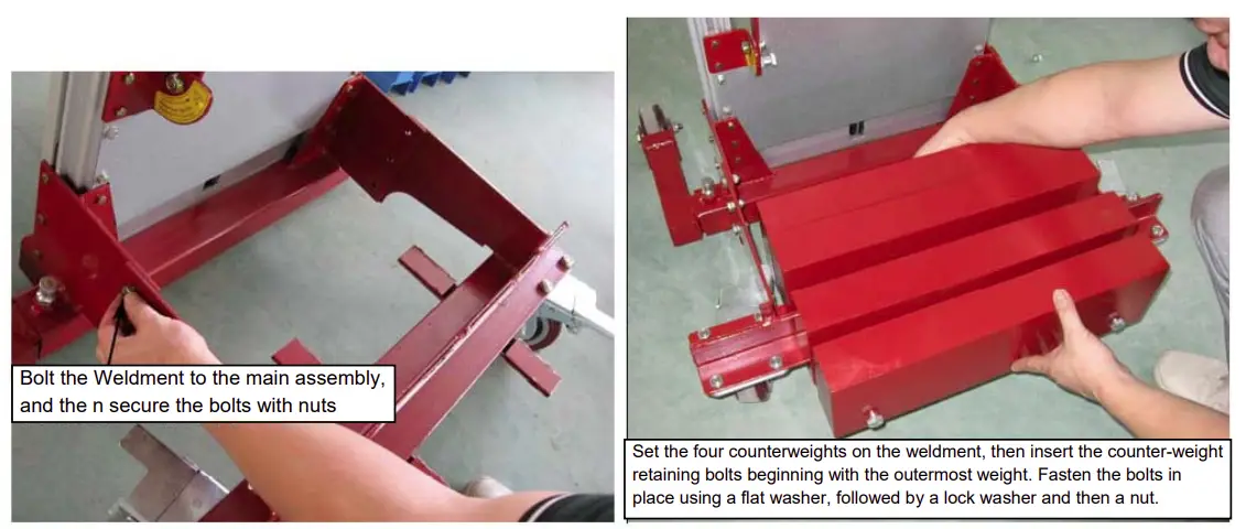
Step 4: Lift the assembly to the upright position (photo A), lock the brakes (photo B) and fasten the winch handle to the winch body.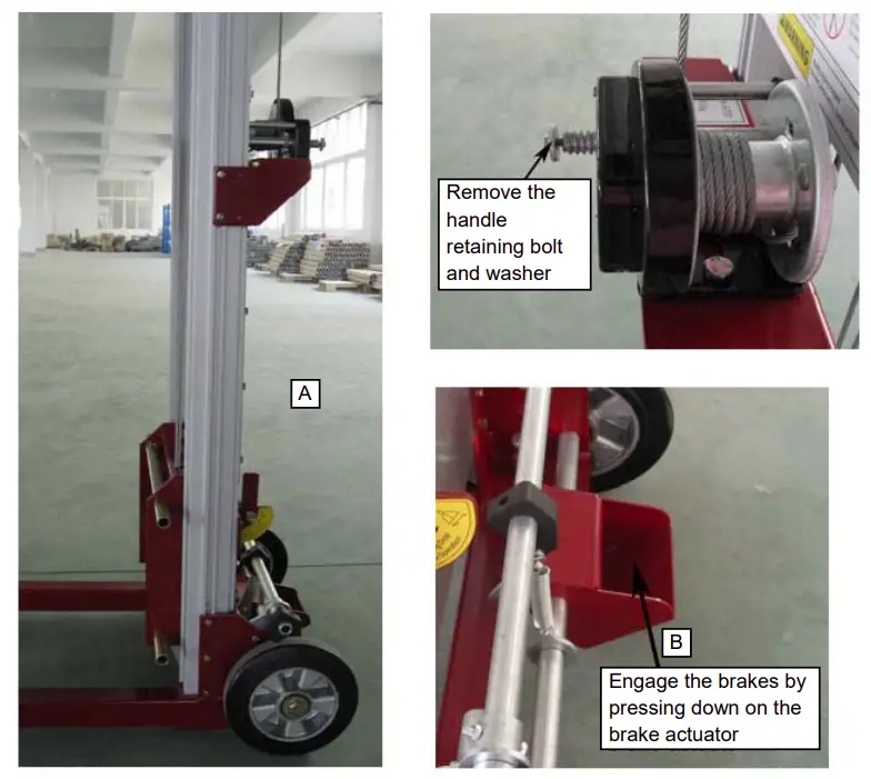
Step 5: Attach the forks to the carriage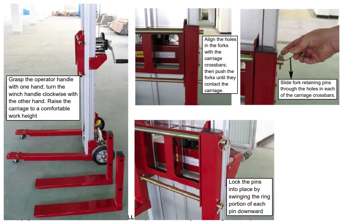
(OPTIONAL) Step 6: Attaching the deck platform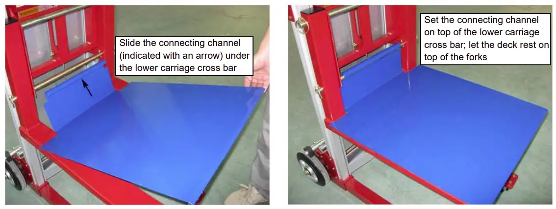
FUNCTIONS TESTS
The Function Tests are designed to discover any malfunctions before the machine is put into service. A malfunctioning machine should be removed from service immediately. Repairs to the machine may only be made by a qualified service technician, using only genuine Wesco parts. After repairs are completed, the operator must perform a pre-operation inspection and function tests again before putting the machine into service.
Do Not Operate Unless:
- A per-operation inspection is performed.
- Function tests prior to use are performed.
- Inspection of the workplace is conducted.
- Only using the machine for its intended functions.
- Being aware of and avoiding the following hazardous environmental conditions:
• Drop-offs or holes
• Bumps and floor obstructions
• Debris
• Overhead obstructions and high voltage conductors
• Hazardous locations
• Inadequate surface support to withstand all load forces imposed by the machine
• Wind and weather conditions
• All other possible unsafe conditions
Test the Brake Operation (if equipped)
- Press down on the food pedal to lock the brake.
- Push the machine. The wheels should not roll.
- Pull up on the foot pedal to release the brake.
- Push the machine. The machine should move freely once again.
Test the Winch Operation
Note: The 273514 model does not have an inner frame.
- Rotate the winch handle clockwise to raise the carriage. The carriage should rise to the top of the inner frame and then the inner frame should rise. The carriage and inner frame should move smoothly, free of hesitation.
- Rotate the winch handle counterclockwise to lower the carriage. The inner frame and the carriage should lower into the outer frame. The carriage and inner frame should move smoothly, free of hesitation.
OPERATION
Using the machine for any purpose other than lifting material is unsafe.
Raising and Lowering Load-Manual Winch
- Center the load on the forks or load platform
- Raise the load by firmly grasping the winch handle and rotating it clockwise. Do not allow the cable to wind unevenly onto the winch drum.
- Lower the load by firmly grasping the winch handle and rotating it counterclockwise. After lowering to the desired position, turn the winch handle clockwise (raise the load)1/4 turn to set the brake.
Moving Machine with a Load
It is best to move the machine on the work site with no load. Moving a raised load should be restricted to positioning for loading and unloading. If it is necessary to move the machine with a raised load, understand and obey the following safety rules:
- Make sure the area is level and clear of obstructions
- Make sure the load is centered on the forks or load platform
- Avoid sudden starts and stops
- Travel with the load in the lowest possible position
- Keep personnel away from the machine and load
- Do not tilt the machine back with a raised load
Transporting Unit
When transporting the unit, the following must be observed:
- Be sure the vehicle capacity and loading surfaces are sufficient to support the machine weight. See Specifications section.
- Do not load machine onto a vehicle unless it is parked on a level surface.
- Remove the load from the forks, boom or load platform before loading for transport.
- The transport vehicle must be secured to prevent rolling while the machine is being loaded.
- The machine must be securely fastened to the transport vehicle.
Loading for Transport
- Fully lower the carriage.
- Rotate the carriage hold-down bar over the carriage. Be sure the lock pin snaps into place.
- Remove the winch handle, reverse the handle and install it. The handle grip should face the carriage.
Positioning Load
Failure to properly position the load may result in death or serious injury
- Determine the weight of the load and the location of its load center.
- Place the load so that it rests on the forks, as close to the carriage as possible.
- Position the load so that the load center is within the load center zone.
WARNING: Tip-over hazard: Raising a load that exceeds the machine capacity may result in death of serious injury. A load center is defined as the balancing point (center of gravity) of a load and must be positioned within the load center zone.
WARNING: Tip-over hazard: Failure to position the load center within the load center zone may result in may death or serious injury.
Long-term Storage
To prepare the machine for long term storage, remove the forks and legs and reverse the winch handle. Select a safe storage location-firm level surface, weather protected, clear of obstruction and traffic.
PART INFORMATION
PART DIAGRAM
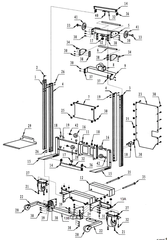
PART LIST
| Item | Part # | Item Description | Qty. |
| 1 | Left Mast Frame | 1 | |
| 2 | Gasket | 30 | |
| 3 | Right Mast Frame | 1 | |
| 4 | Inner Frame | 2 | |
| 5 | Up Support Frame Assembly | 1 | |
| 6 | 273596 | Operator Handle | 1 |
| 7 | 273590 | Decal Plate (For 273516) | 1 |
| 8 | 273547 | Manual Winch | 1 |
| 9 | Winch Mounting Support Bracket | 1 | |
| 10 | Limit Position Assembly | 1 | |
| 11 | 273536 | Carriage | 1 |
| 12 | Counterweight Base | 2 | |
| 13A | 273551 | Counterweight Support Weldment | 1 |
| 13B | |||
| 14 | Beam | 2 | |
| 15 | 273538 | Fork | 2 |
| 16 | Roller Wheel | 4 | |
| 17 | 273531 | Upper and Lower Pulley | 3 |
| 18 | 273546 | Fork Lock Pin | 4 |
| 19 | 273537 | Carriage Crossbars | 2 |
| 20 | 273542 | Fixed Wheel 4” | 1 |
| 21 | Hexagon Headed Bolt M10 x 25 | 1 | |
| 22 | Adjustable Leg | 2 | |
| 23 | 273597 | Baffle Plate | 1 |
| 24 | 273540 | Spacer Pin | 2 |
| 25 | Square Nut M6 | 2 | |
| 26 | Flat Head Screw M6 x 20 | 2 | |
| 27 | 273543 | Swivel Caster 5” | 2 |
| 28 | Spring Pin | 1 | |
| 29 | 273518 | Deck Platform (Option) | 1 |
| 30 | Hexagon Bolt M6x12 | 38 | |
| 31 | Hexagon Bolt M8x25 | 8 | |
| 32 | 273532 | Hexagon Bolt M10x60 | 3 |
| 33 | 273952 | Hexagon Bolt M12x70 | 2 |
| 34 | Hexagon Bolt M12x25 | 2 | |
| 35 | 273555 | Hexagon Bolt M14x90 | 2 |
| 36 | Fastness Plate (Short) | 8 | |
| 37 | Fastness Plate | 2 | |
| 38 | Fastness Plate (Long) | 6 | |
| 39 | Elongated Fastness Plate | 2 | |
| 40 | Cable Ring | 1 | |
| 41 | 273530 | Loading Wheels 4” | 2 |
| 42 | Roll Wheel Central Spindle | 4 | |
| 273554 | Cable: 350 lbs (For 273515) | 1 | |
| 273553 | Cable: 400 lbs (For 273516) | 1 | |
| 273552 | Cable: 500 lbs (For 273517) | 1 |