OMRON UMA Series Easy To Safety Mat with Advanced Features Owner’s Manual

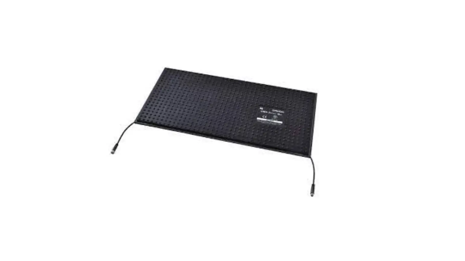
Safety Mat UMA Series
- Easy-to-install safety mat with advanced features
- 1 and 2 cable types
- Meets EN ISO 13849-1 (PLd/Safety Category 3) and EN ISO 13856-1
- Can be used with MC3 Safety Mat Controller, SCC-1224A Safety Mat/Edge Controller or NX Safety Controller
- Complies with North American safety standards including ANSI/RIA 15.06
Model Number Structure

- Measurement Unit
None: Inch
M: mm - Color
None: Black
Y: Yellow - Safety Mat Dimension A
- Safety Mat Dimension B
- Number of Cables
- 1 cable (4-wire type)
- 2 cables (2-wire type)
Ordering Information
Safety Mats
1-cable Mats
| Appearance | Dimensions | Black | Yellow | |
| A (mm) | B (mm) | Model | Model | |
 | 300 | 300 | UMMA-0300-0300-1 | UMMYA-0300-0300-1 |
| 400 | 400 | UMMA-0400-0400-1 | UMMYA-0400-0400-1 | |
| 500 | 250 | UMMA-0500-0250-1 | UMMYA-0500-0250-1 | |
| 500 | 400 | UMMA-0500-0400-1 | UMMYA-0500-0400-1 | |
| 500 | 500 | UMMA-0500-0500-1 | UMMYA-0500-0500-1 | |
| 500 | 1500 | UMMA-0500-1500-1 | UMMYA-0500-1500-1 | |
| 600 | 400 | UMMA-0600-0400-1 | UMMYA-0600-0400-1 | |
| 750 | 250 | UMMA-0750-0250-1 | UMMYA-0750-0250-1 | |
| 750 | 500 | UMMA-0750-0500-1 | UMMYA-0750-0500-1 | |
| 750 | 750 | UMMA-0750-0750-1 | UMMYA-0750-0750-1 | |
| 750 | 1500 | UMMA-0750-1500-1 | UMMYA-0750-1500-1 | |
| 1000 | 500 | UMMA-1000-0500-1 | UMMYA-1000-0500-1 | |
| 1000 | 750 | UMMA-1000-0750-1 | UMMYA-1000-0750-1 | |
| 1000 | 1000 | UMMA-1000-1000-1 | UMMYA-1000-1000-1 | |
| 1000 | 1250 | UMMA-1000-1250-1 | UMMYA-1000-1250-1 | |
| 1000 | 1500 | UMMA-1000-1500-1 | UMMYA-1000-1500-1 | |
2-cable Mats
| Appearance | Dimensions | Black | Yellow | |
| A (mm) | B (mm) | Model | Model | |
 | 300 | 300 | UMMA-0300-0300-2 | UMMYA-0300-0300-2 |
| 400 | 400 | UMMA-0400-0400-2 | UMMYA-0400-0400-2 | |
| 500 | 250 | UMMA-0500-0250-2 | UMMYA-0500-0250-2 | |
| 500 | 400 | UMMA-0500-0400-2 | UMMYA-0500-0400-2 | |
| 500 | 500 | UMMA-0500-0500-2 | UMMYA-0500-0500-2 | |
| 500 | 1500 | UMMA-0500-1500-2 | UMMYA-0500-1500-2 | |
| 600 | 400 | UMMA-0600-0400-2 | UMMYA-0600-0400-2 | |
| 750 | 250 | UMMA-0750-0250-2 | UMMYA-0750-0250-2 | |
| 750 | 500 | UMMA-0750-0500-2 | UMMYA-0750-0500-2 | |
| 750 | 750 | UMMA-0750-0750-2 | UMMYA-0750-0750-2 | |
| 750 | 1500 | UMMA-0750-1500-2 | UMMYA-0750-1500-2 | |
| 1000 | 500 | UMMA-1000-0500-2 | UMMYA-1000-0500-2 | |
| 1000 | 750 | UMMA-1000-0750-2 | UMMYA-1000-0750-2 | |
| 1000 | 1000 | UMMA-1000-1000-2 | UMMYA-1000-1000-2 | |
| 1000 | 1250 | UMMA-1000-1250-2 | UMMYA-1000-1250-2 | |
| 1000 | 1500 | UMMA-1000-1500-2 | UMMYA-1000-1500-2 | |
Trims
| Appearance | Name | Model | Remarks |
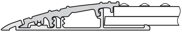 | Ramp Trim with Yellow PVC Cover (1.22 m) | UMRT4 | Installed on the perimeter of the Safety Mat. Each Trim is composed of two parts, an aluminum base and a PVC Cover. Possible to install cables inside. |
| Ramp Trim with Yellow PVC Cover (2.44 m) | UMRT8 | ||
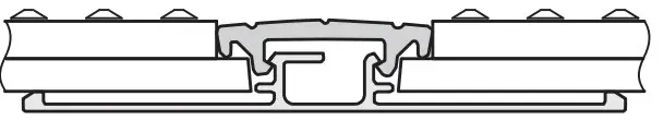 | Joining Trim (1.22 m) | UMJS4 | The Joining Trims join the Safety Mats when two or more Safety Mats are being combined. In addition to joining the Safety Mats, the Joining Trims preserve the Safety Mat’s sensitivity at the joints. Possible to install cables inside except M8 connector portion. |
| Joining Trim (2.44 m) | UMJS8 | ||
| | Aluminum Ramp Trim (2.44 m) | UMAL | Installed on the perimeter of the Safety Mat. |
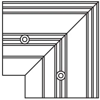
 | Molded Outside Corner | UMOC | Installed at the outside corners of the Safety Mat combining with Ramp Trims with Yellow PVC Cover. |
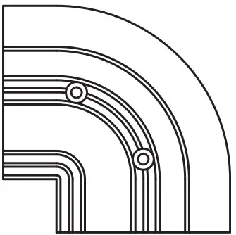
 | Molded Inside Corner | UMIC | Installed at the inside corners when two or more Safety Mats combining with Ramp Trims with Yellow PVC Cover are being combined. |
Note: 12 screws (No. 8-32 × 1.25″) and 12 anchors are included with Ramp Trim with Yellow PVC Cover (UMRT4 and UMRT8) and Aluminum
Ramp Trim (UMAL).
Trim Kits (Not Including Safety Mat)
| Applicable Safety Mat | Trim Kit model | Remarks | |
| Black | Yellow | ||
| UMMA-0300-0300-@ | UMMYA-0300-0300-@ | MTKCA-0300-0300 |
|
| UMMA-0400-0400-@ | UMMYA-0400-0400-@ | MTKCA-0400-0400 | |
| UMMA-0500-0250-@ | UMMYA-0500-0250-@ | MTKCA-0500-0250 | |
| UMMA-0500-0400-@ | UMMYA-0500-0400-@ | MTKCA-0500-0400 | |
| UMMA-0500-0500-@ | UMMYA-0500-0500-@ | MTKCA-0500-0500 | |
| UMMA-0500-1500-@ | UMMYA-0500-1500-@ | MTKCA-0500-1500 | |
| UMMA-0600-0400-@ | UMMYA-0600-0400-@ | MTKCA-0600-0400 | |
| UMMA-0750-0250-@ | UMMYA-0750-0250-@ | MTKCA-0750-0250 | |
| UMMA-0750-0500-@ | UMMYA-0750-0500-@ | MTKCA-0750-0500 | |
| UMMA-0750-0750-@ | UMMYA-0750-0750-@ | MTKCA-0750-0750 | |
| UMMA-0750-1500-@ | UMMYA-0750-1500-@ | MTKCA-0750-1500 | |
| UMMA-1000-0500-@ | UMMYA-1000-0500-@ | MTKCA-1000-0500 | |
| UMMA-1000-0750-@ | UMMYA-1000-0750-@ | MTKCA-1000-0750 | |
| UMMA-1000-1000-@ | UMMYA-1000-1000-@ | MTKCA-1000-1000 | |
| UMMA-1000-1250-@ | UMMYA-1000-1250-@ | MTKCA-1000-1250 | |
| UMMA-1000-1500-@ | UMMYA-1000-1500-@ | MTKCA-1000-1500 | |
Note
- Put 1 in the box (@) in the model number for 1-cable Mat or 2 for 2-cable Mat.
- 24 screws (No. 8-32 × 1.25″) and 24 anchors are included with a Trim Kit.
- The length of the Ramp Trims with Yellow PVC Covers has been made to fit mat dimensions A and B. PVC Trim Cover = (Mat dimensions A and B) – 50.8 mm
Safety Mat Controller
| Product | Appearance | Safety outputs | Auxiliary outputs | Rated voltage | Terminal block type | Model |
| Safety Mat Controller | 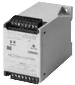 | SPDT-NO | SPDT-NC | 24 VDC | Screw terminals | MC3 |
| Safety Mat/ Edge Controller * | 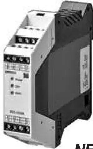 | SPDT-NO | SPST-NO | 120 VACor24 VAC/DC | Screw terminals | SCC-1224A |
Can also be connected with SGE-series Safety Edges.
Refer to the SCC-1224A Safety Mat/Edge Controller User Manual (Cat. No. Z394) for details.
Accessories
Using with 1-cable Mats
Connecting a 1-cable Mat to a MC3 Safety Mat Controller, SCC-1224A Safety Mat/Edge Controller or NX-series Safety Controller.
Cables
| Appearance | Name | Length | Remarks | Model |
 | Single Connector Cable | 2 m | Single connector cable to connect a 1-cable Mat (UM@@A-@-@-1) to a Controller. M8, 4-socket | UMA-CBL-4PCF-M8-02M |
| 5 m | UMA-CBL-4PCF-M8-05M | |||
| 10 m | UMA-CBL-4PCF-M8-10M | |||
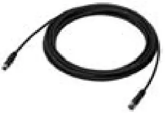
| Male-Female Extension Cable | 2 m | Extension cable to connect a 1-cable Mat (UM@@A-@-@-1) to a Controller. M8, 4-pin | UMA-CBL-4PMF-M8-02M |
| 5 m | UMA-CBL-4PMF-M8-05M | |||
| 10 m | UMA-CBL-4PMF-M8-10M |
Using with 2-cable Mats
Connecting a 2-cable Mat to a MC3 Safety Mat Controller, SCC-1224A Safety Mat/Edge Controller or NX-series Safety Controller.
Cables
| Appearance | Name | Length | Remarks | Model |
| Single Connector Cable | 2 m | Single connector cable to connect a 2-cable Mat (UM@@A-@-@-2) to a Controller. M8,3-socket | UMA-CBL-3PCF-M8-02M |
| 5 m | UMA-CBL-3PCF-M8-05M | |||
| 10 m | UMA-CBL-3PCF-M8-10M | |||
| Male-Female Extension Cable | 2 m | Extension cable to connect a 2-cable Mat (UM@@A-@-@-2) to a Controller. M8,3-pin | UMA-CBL-3PMF-M8-02M |
| 5 m | UMA-CBL-3PMF-M8-05M | |||
| 10 m | UMA-CBL-3PMF-M8-10M |
Male-Male Extension Cable and Female-Female Extension Cable
| Appearance | Name | Length | Remarks | Model |
| M8, 3-pin Male to Male Extension Cable | 0.15 m | To be used to connect the connector sockets of 2- cable UMA Safety Mat together. | UMA-CBL-3PMM-M8-0.15M |
 | M8, 3-pin Female to Female Extension Cable | 0.15 m | To be used to connect the connector plugs of 2- cable UMA Safety Mat together. | UMA-CBL-3PFF-M8-0.15M |
Terminating Resistor
| Appearance | Remarks | Model |
 | Terminating resistor, 8.2 kLTo be used to connect a 2-cable Mat (UM@@A-@-@-2) to an SCC-1224A Safety Mat/Edge Controller. | UMA-TRES |
Specifications
| Detection Method | Pressure sensitive |
| Mat Type | Normally open SPST |
| Mat Electrical Rating | 20.4 V to 28.8 V |
| Activation Force | 300 N min. to 80 mm dia. test piece |
| Maximum Load | 2,000 N to 80 mm dia. test piece1,862 kPa (270 lbs/in.2) (rolling load (stationary)) |
| Response Time | 50 ms max. |
| Mechanical Durability | 1 x 10⁶ operations min. |
| Mat Exit Cable | Model No. ending ‘-1’: 1 exit cable, M8 4-pin cable, 4 conductors, 22 AWG, maleModel No. ending ‘-2’: 2 exit cables, M8 3-pin cable, 2 conductors, 22 AWG, 1 male and 1 female |
| Ambient operating temperature | -10 to 55°C (14 to 131°F) (with no icing or condensation) |
| Ambient storage temperature | -10 to 55°C (14 to 131°F) (with no icing or condensation) |
| Ambient operating humidity | 0 to 95% RH |
| Degree of protection | IP65 |
| Material (Mat cover) | Polyurethane |
| Weight | Approx. 25 kg/m2 |
Safety Mat Controller
Ratings
| Item Model | MC3 | SCC-1224A |
| Power voltage | 24 VDC | 120 VAC 50/60Hz (Terminals A1 and A2)24 VAC 50/60Hz or 24 VDC (Terminals B1 and B2) |
| Operating voltage range | -15% to +15% of rated supply voltage | -10% to +10% of rated supply voltage |
| Power consumption * | 3 W max. | 120 VAC: 3.8 VA max. 50 Hz, 3.5 VA max. 60 Hz24 VAC: 1.2 VA max., 24 VDC: 1.5 W max. |
| Rated load | 6 A at 230 VAC/6 A at 24 VDC (resistive load)5 A at 230 VAC (AC15)/2 A at 24 VDC (DC13) (inductive load) | 3 A at 230 VAC/3 A at 24 VDC (resistive load)1 A at 230 VAC (AC15)/2 A at 24 VDC (DC13) (inductive load) |
Power consumption of loads is not included.
Characteristics
| Item Model | MC3 | SCC-1224A | |
| Response time | 30 ms max. | 13 ms max. | |
| Safety input | Mat can be connected in series (Connectable number: 12 max.) The external impedance must be 8 L or less between M11 and M21 and between M12 and M22. | Mat can be connected in series (Connectable number: 10 max.) | |
| Safety output | SPDT-NO | SPDT-NO | |
| Auxiliary output | SPDT-NC | SPST-NO | |
| Dielectric strength | Between different poles of outputs | 1,800 VAC, 50/60 Hz for 1 sec. | 1,500 VAC, 50/60 Hz for 1 sec. |
| Between power supply and output | |||
| Vibration resistance | Malfunction: 10 to 55 Hz, 0.15 mm single amplitude | Malfunction: 10 to 55 Hz, 0.15 mm single amplitude | |
| Mechanical shock resistance | Malfunction: 98 m/s2 | Malfunction: 147 m/s2 | |
| Durability | Mechanical | 10,000,000 cycles min. | 1,000,000 cycles min. |
| Electrical | 100,000 cycles min. (rated load, switching frequency: 360 cycles/hour) | AC-15: 800,000 cycles min. (1A at 230 VAC) DC-13: 250,000 cycles min. (2A at 24 VDC) | |
| Ambient operating temperature | 0 to 55°C (with no icing or condensation) | -20 to 55°C (with no icing or condensation) | |
| Ambient operating humidity | 0% to 90% RH | 0% to 90% RH | |
| Degree of protection | IP20 | IP20 | |
| Terminal tightening torque | 0.5 N·m | 0.5 to 0.6 N·m | |
| Weight | Approx. 360 g | Approx. 210 g | |
Approvals
| Item Model | MC3 | SCC-1224A |
| Conforming to Standards | EN ISO13856-1:2013, EN ISO13849-1:2015, ANSI/UL 508, CSA C22.2 No. 14 | EN ISO 13856-1:2013, EN ISO 13849-1:2015, ANSI/UL 508, CSA C22.2 No. 14 |
| Performance level (PL)/ safety category * | PL d/safety category 3 (EN ISO 13849-1:2015) | PL d/safety category 3 (EN ISO 13849-1:2015) |
| PFHd * | 4.8×10⁻⁸ | 6.5×10⁻⁹ |
Installation
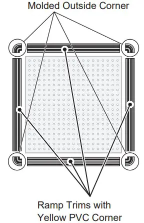
Using Trim Pieces
Ramp Trim with Yellow PVC Cover: UMRT4/UMRT8
Secures the edges of the Safety Mats to the floor.
It is composed of two parts with an aluminum base and a PVC Cover.
In this case, the perimeter of the Safety Mat is about 4 m and the following pieces are required:
The example above consists of the following components:
UMMA-1000-1000 Safety Mat : 1 piece
UMRT4 Ramp Trim with Yellow PVC Cover (1.22 m) : 4 pieces
UMOC Molded Outside Corner : 4 pieces
Joining Trim: UMJS4/UMJS8
The Joining Trims join the Safety Mats when two or more Safety Mats
are being combined.
In addition to joining the Safety Mats, the Joining Trims preserve the
Safety Mat’s sensitivity at the joints.
Aluminum Ramp Trim: UMAL
Secures the edges of the Safety Mat to the floor.
The Aluminum Ramp Trim is hollow, so cable can be routed through it.
Molded Outside Corner: UMOC
Used together with the Ramp Trim with Yellow PVC Cover (UMRT4/ UMRT8) to secure the external corners of the Safety Mats to the floor.
Molded Inside Corner: UMIC
Used together with the Ramp Trim with Yellow PVC Cover (UMRT4/ UMRT8) to secure the internal corners of the Safety Mats to the floor.
Note:
- The Aluminum Ramp Trim or Ramp Trim with Yellow PVC
Cover must be cut to fit the size of the Safety Mats being used. Furthermore, when the Safety Mat’s wiring is being routed through the Aluminum Ramp Trim or Ramp Trim with Yellow PVC Cover, it will be necessary to cut or notch the Aluminum Ramp Trim or Ramp Trim with Yellow PVC Cover for cable access. Refer to UMA Safety Mat User Manual (Man. No. Z375-E1) for details on cutting or notching the Aluminum Ramp Trim or Ramp Trim with Yellow PVC Cover. - The Joining Trim must be cut to fit the size of the Safety Mats being used.
- The Ramp Trim with Yellow PVC Cover and Molded Corner must be anchored to the floor to secure the Safety Mats. It is also necessary to drill holes in the Trim to anchor it. Refer to UMA Safety Mat User Manual (Man. No. Z375-E1) for details on drilling holes in the Trim and Molded Corner
Safety Mat Configuration
The Safety Mats are secured by anchoring the Ramp Trim with Yellow PVC Cover and Molded Corner to the floor. Before ordering, confirm the number of Ramp Trim with Yellow PVC Cover and Molded Corner pieces that will be needed.
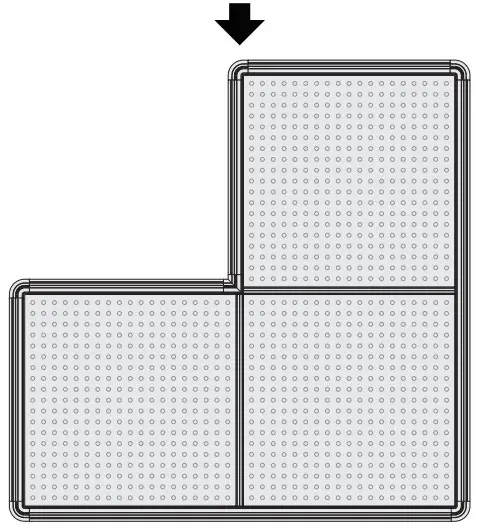
Example 1: Using a Single Safety Mat
In this case, the perimeter of the Safety Mat is about 8 m, the joint between the Safety Mats is 2-m long, and the following pieces are
required:
The example above consists of the following components:
UMMA-1000-1000 Safety Mat : 3 pieces
UMRT4 Ramp Trim with Yellow PVC Cover (1.22 m) : 8 pieces
UMJS4 Joining Trim (1.22 m) : 2 pieces
UMOC Molded Outside Corner : 5 pieces
UMIC Molded Inside Corner : 1 piece
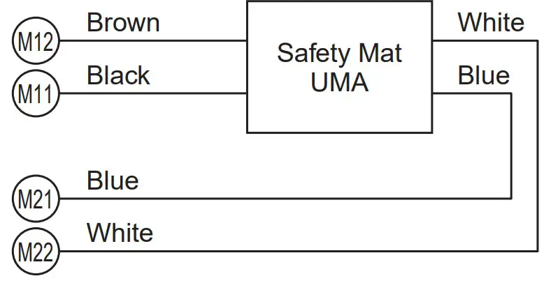
Connection Examples of Safety Mat and Controller
Using a Single Safety Mat
Connecting a 1-cable Mat (UM@@A-@-@-1) to a MC3 Safety Mat Controller or SCC-1224A Safety Mat/Edge Controller.
Using Multiple Safety Mats
- Connecting three 2-cable Mats (UM@@A-@-@-2) to a SCC-1224A Safety Mat/Edge Controller

- Connecting three 2-cable Mats (UM@@A-@-@-2) to a MC3 Safety Mat Controller

UMA-CBL-3PMM-M8-0.15M UMA-CBL-3PCF-M8-@M
M8 3-pin single connector cable
M8 3-pin male-male extension cable
- When an MC3 is used, the total cable length is up to 100 m and up to 12 Safety Mats can be connected (up to 10 m2 in total).
When an SCC-1224A is used, the total cable length is up to 25 m and up to 10 Safety Mats can be connected (up to 10 m2 in total). For the 1-cable type of UMA Safety Mat (UM@@A-@-@-1), the total lone length of cable must be calculated by multiplying the total length of the cables used by two. - The required accessories vary depending on the mat configuration and layout.
Connections
MC3
Internal Connection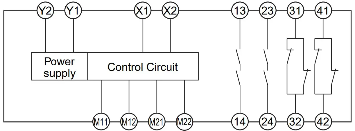
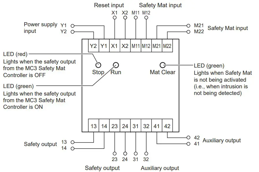
Wiring of Inputs and Outputs
Changing the Reset Mode
You can select either the Auto Reset Mode or the Manual Reset Mode with the MC3 Controller. Remove the terminal block from the top of the MC3 Controller to expose three yellow jumpers. Set the jumps as required by system specifications.
Auto Reset Mode (Factory Setting)
Leave all three jumpers connected.
Signal Indicators
| Label | Color | Name | Status | Description |
| Power | Green | Power LED | ON | Operating state |
| Flashing | Fault alarm | |||
| CH1 | Red | Sensor Input LED | ON | Sensor activated (Safety output OFF) |
| Fast flashing (approx. 4 Hz) | Sensor faulty | |||
| Slow flashing (approx. 1 Hz) | Waiting for reset switch input (Safety output OFF) | |||
| OFF | Released from interlocked state (Safety output ON) | |||
| AUX1 | Yellow | Auxiliary output LED | ON | Auxiliary output contact closed |
| OFF | Auxiliary output contact open |
Dimensions
- cable mat
UM@@A-@-@-1 - cable mat
UM@@A-@-@-2
The UM@@A-@-@-1 mat comes with a short 4-conductor quick disconnect cables with M8 4-pin connector at a corner of the safety mat.
The UM@@A-@-@-2 mat comes with two short 2-conductor quick disconnect cables with M8 3-pin connector at two corners of the safety mat.
- Refer to Model Number Structure on page 1 for more information.
- “Step” portion of mat (inactive) is used to “seat/place/hold” trim.
- The mat has the following inactive (non-sensing) area:
– 10 mm (20 mm at corners) with a test piece of 80 mm diameter
– 15 mm (30 mm at corners) with a test piece of 11 mm diameter
Example dimensions: UMMA-0500-0500-@
Mat Controller
MC3
Safety Mat/Edge Controller
SCC-1224A
Accessories
Cables
Using with 1-Cable Mats
Single Connector Cable (M8, 4-socket)
Single connector cable to connect a 1-cable UMA Safety Mat to a MC3 Safety Mat Controller, SCC1224A Safety Mat/Edge Controller or NX-series Safety Controller.
UMA-CBL-4PCF-M8-@M
| Model | L (m) |
| UMA-CBL-4PCF-M8-02M | 2 |
| UMA-CBL-4PCF-M8-05M | 5 |
| UMA-CBL-4PCF-M8-10M | 10 |
Male-Female Extension Cable (M8, 4-pin)
Extension cable to connect a 1-cable UMA Safety Mat to a UMA-CBL-4PCF-M8-@M Single
Connector Cable.
UMA-CBL-4PMF-M8-@M
| Model | L (m) |
| UMA-CBL-4PMF-M8-02M | 2 |
| UMA-CBL-4PMF-M8-05M | 5 |
| UMA-CBL-4PMF-M8-10M | 10 |
Using with 2-Cable Mats
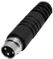
Single Connector Cable (M8, 3-socket)
Single connector cable to connect a 2-cable UMA Safety Mat to a MC3 Safety Mat Controller,
SCC-1224A Safety Mat/Edge Controller or NX-series Safety Controller.
UMA-CBL-3PCF-M8-@M
| Model | L (m) |
| UMA-CBL-3PMF-M8-02M | 2 |
| UMA-CBL-3PMF-M8-05M | 5 |
| UMA-CBL-3PMF-M8-10M | 10 |
Male-Female Extension Cable (M8, 3-pin)
Extension cable to connect a 2-cable UMA Safety Mat to a UMA-CBL-3PCF-M8-@M
Single Connector Cable or connect multiple 2-cable UMA Safety Mats in series.
UMA-CBL-3PMF-M8-@M
Model | L (m) |
| UMA-CBL-3PMF-M8-02M | 2 |
| UMA-CBL-3PMF-M8-05M | 5 |
| UMA-CBL-3PMF-M8-10M | 10 |
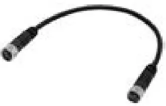
Male-Male Extension Cable (M8, 3-pin)
Used to connect the connector sockets of 2-cable UMA Safety Mats together.
UMA-CBL-3PMM-M8-0.15M
Female-Female Extension Cable (M8, 3-pin)
Used to connect the connector plugs of 2-cable UMA Safety Mats together.
UMA-CBL-3PFF-M8-0.15M
Terminating Resistor
Used to connect a 2-cable Mat (UM@@A-@-@-2) to an SCC-1224A Safety Mat/Edge Controller.
Trims
Application Examples
Highest achievable PL/ safety category | Model | Stop category | Reset |
| PLd/3 equivalent | Safety Mat UMA series Mat Controller MC3 | 0 | Manual |
Note: The above PL is only the evaluation result of the example. The PL must be evaluated in an actual application by the customer after confirming
the usage conditions.
Application Overview
- The power supply to the motor M is turned OFF when a person steps on the mat.
- The power supply to the motor M is kept OFF until the reset switch S1 is pressed after the person steps out of the mat
Note: Remove the three yellow jumpers from the MC3 to use Manual Reset Mode. Refer to Changing the Reset Mode on page 10 for the location of the jumpers.
| Highest achievable PL/ safety category | Model | Stop category | Reset |
| PLd/3 equivalent | Safety Mat UMA seriesSafety Mat/Edge Controller SCC-1224A Safety Relay Unit G9SA-301 | 0 | Auto |
Note: The above PL is only the evaluation result of the example. The PL must be evaluated in an actual application by the customer after confirming the usage conditions.
Application Overview
- The power supply to the motor M is turned OFF when a person steps on the mat.
- The power supply to the motor M is kept OFF until the reset switch S1 is pressed after the person steps out of the mat.
| Highest achievable PL/ safety category | Model | Stop category | Reset |
| PLd/3 equivalent | Safety Mat UMA series Safety Mat/Edge Controller SCC-1224A Safety Relay Unit G9SA-301 | 0 | Auto |
Note: The above PL is only the evaluation result of the example. The PL must be evaluated in an actual application by the customer after confirming the usage conditions.
- Automatic reset (DIP Switch1: ON)
- Auxiliary output without delay mode
(DIP Switch 2: ON) - Internal terminating resistor used
Related Manuals
| Man. No. | Model | Manual name |
| Z375 | UMA | UMA Safety Mat User Manual |
| Z394 | SCC-1224A | SCC-1224A Safety Mat/Edge Controller User Manual |


