![]() CIDRW SYSTEM
CIDRW SYSTEM
V640 SERIES
USER’S MANUAL
AMPLIFIER UNITS
V640-HAM11-ETN-V2
V640-HAM11-L-ETN-V2
CIDRW HEADS
V640-HS61
V640-HS62
Introduction
Thank you for purchasing the V640-series CIDRW System.
Please observe the following points when operating the V640-series CIDRW System:
- Allow the CIDRW System to be installed and operated only by qualified specialist with a sufficient knowledge of electrical systems.
- Please read and understand the contents of this manual before using the system.
- After reading this manual, store it in a convenient location for easy reference whenever necessary.
CIDRW System
| V640-HAM11-ETN-V2 | Amplifier Unit |
| V640-HAM11-L-ETN-V2 | Amplifier Unit |
| V640-HS61 | CIDRW Head |
| V640-HS62 | CIDRW Head |
User’s Manual
READ AND UNDERSTAND THIS DOCUMENT
Please read and understand this document before using the products. Please consult your OMRON representative if you have any questions or comments.
WARRANTY
OMRON’s exclusive warranty is that the products are free from defects in materials and workmanship for a period of one year (or other period if specified) from date of sale by OMRON.
OMRON MAKES NO WARRANTY OR REPRESENTATION, EXPRESS OR IMPLIED, REGARDING NONINFRINGEMENT, MERCHANTABILITY, OR FITNESS FOR PARTICULAR PURPOSE OF THE PRODUCTS. ANY BUYER OR USER ACKNOWLEDGES THAT THE BUYER OR USER ALONE HAS DETERMINED THAT THE PRODUCTS WILL SUITABLY MEET THE REQUIREMENTS OF THEIR INTENDED USE. OMRON DISCLAIMS ALL OTHER WARRANTIES, EXPRESS OR IMPLIED.
LIMITATIONS OF LIABILITY
OMRON SHALL NOT BE RESPONSIBLE FOR SPECIAL, INDIRECT, OR CONSEQUENTIAL DAMAGES, LOSS OF PROFITS OR COMMERCIAL LOSS IN ANY WAY CONNECTED WITH THE PRODUCTS, WHETHER SUCH CLAIM IS BASED ON CONTRACT, WARRANTY, NEGLIGENCE, OR STRICT LIABILITY.
In no event shall responsibility of OMRON for any act exceed the individual price of the product on which liability is asserted.
IN NO EVENT SHALL OMRON BE RESPONSIBLE FOR WARRANTY, REPAIR, OR OTHER CLAIMS REGARDING THE PRODUCTS UNLESS OMRON’S ANALYSIS CONFIRMS THAT THE PRODUCTS WERE PROPERLY HANDLED, STORED, INSTALLED, AND MAINTAINED AND NOT SUBJECT TO CONTAMINATION, ABUSE, MISUSE, OR INAPPROPRIATE MODIFICATION OR REPAIR.
SUITABILITY FOR USE
THE PRODUCTS CONTAINED IN THIS DOCUMENT ARE NOT SAFETY RATED. THEY ARE NOT DESIGNED OR RATED FOR ENSURING SAFETY OF PERSONS, AND SHOULD NOT BE RELIED UPON AS A SAFETY COMPONENT OR PROTECTIVE DEVICE FOR SUCH PURPOSES. Please refer to separate catalogs for OMRON’s safety rated products.
OMRON shall not be responsible for conformity with any standards, codes, or regulations that apply to the combination of products in the customer’s application or use of the product.
At the customer’s request, OMRON will provide applicable third party certification documents identifying ratings and limitations of use that apply to the products. This information by itself is not sufficient for a complete determination of the suitability of the products in combination with the end product, machine, system, or other application or use.
The following are some examples of applications for which particular attention must be given. This is not intended to be an exhaustive list of all possible uses of the products, nor is it intended to imply that the uses listed may be suitable for the products:
- Outdoor use, uses involving potential chemical contamination or electrical interference, or conditions or uses not described in this document.
- Nuclear energy control systems, combustion systems, railroad systems, aviation systems, medical equipment, amusement machines, vehicles, safety equipment, and installations subject to separate industry or government regulations.
- Systems, machines, and equipment that could present a risk to life or property.
Please know and observe all prohibitions of use applicable to the products.
NEVER USE THE PRODUCTS FOR AN APPLICATION INVOLVING SERIOUS RISK TO LIFE OR PROPERTY WITHOUT ENSURING THAT THE SYSTEM AS A WHOLE HAS BEEN DESIGNED TO ADDRESS THE RISKS, AND THAT THE OMRON PRODUCT IS PROPERLY RATED AND INSTALLED FOR THE INTENDED USE WITHIN THE OVERALL EQUIPMENT OR SYSTEM.
PERFORMANCE DATA
Performance data given in this document is provided as a guide for the user in determining suitability and does not constitute a warranty. It may represent the result of OMRON’s test conditions, and the users must correlate it to actual application requirements. Actual performance is subject to the OMRON Warranty and Limitations of Liability.
CHANGE IN SPECIFICATIONS
Product specifications and accessories may be changed at any time based on improvements and other reasons.
It is our practice to change model numbers when published ratings or features are changed, or when significant construction changes are made. However, some specifications of the product may be changed without any notice. When in doubt, special model numbers may be assigned to fix or establish key specifications for your application on your
request. Please consult with your OMRON representative at any time to confirm actual specifications of purchased products.
DIMENSIONS AND WEIGHTS
Dimensions and weights are nominal and are not to be used for manufacturing purposes, even when tolerances are shown.
ERRORS AND OMISSIONS
The information in this document has been carefully checked and is believed to be accurate; however, no responsibility is assumed for clerical, typographical, or proofreading errors, or omissions.
PROGRAMMABLE PRODUCTS
OMRON shall not be responsible for the user’s programming of a programmable product, or any consequence thereof.
COPYRIGHT AND COPY PERMISSION
This document shall not be copied for sales or promotions without permission.
This document is protected by copyright and is intended solely for use in conjunction with the product. Please notify us before copying or reproducing this document in any manner, for any other purpose. If copying or transmitting this document to another, please copy or transmit it in its entirety.
Safety Precautions
- Definition of Precautionary Information
The following notation and alert symbols are used in this User’s Manual to provide precautions required to ensure safe usage of a V640-series CIDRW System. The safety precautions that are provided are extremely important to safety. Always read and heed the information provided in all safety precautions.
The following signal words are used in this manual.
![]() WARNING Indicates a potentially hazardous situation which, if not avoided, will result in minor or moderate injury, or may result in serious injury or death. Additionally there may be significant property damage.
WARNING Indicates a potentially hazardous situation which, if not avoided, will result in minor or moderate injury, or may result in serious injury or death. Additionally there may be significant property damage.
- Meanings of Alert Symbols
| Prohibition Indicates general prohibitions for which there is no specific symbol. | |
| Execute Indicates an action of a non-specific, general user. |
- WARNING
![]() WARNING
WARNING![]() Anti-virus protection
Anti-virus protection
Install the latest commercial-quality antivirus software on the computer connected to the control system and maintain to keep the software up-to-date.![]() Security measures to prevent unauthorized access
Security measures to prevent unauthorized access
Take the following measures to prevent unauthorized access to our products.
- Install physical controls so that only authorized personnel can access control systems and equipment.
- Reduce connections to control systems and equipment via networks to prevent access from untrusted devices.
- Install firewalls to shut down unused communications ports and limit communications hosts and isolate control systems and equipment from the IT network.
- Use a virtual private network (VPN) for remote access to control systems and equipment.
- Adopt multifactor authentication to devices with remote access to control systems and equipment.
- Set strong passwords and change them frequently.
- Scan virus to ensure safety of USB drives or other external storages before connecting them to control systems and equipment.
Data input and output protection![]() Validate backups and ranges to cope with unintentional modification of input/output data to control systems and equipment.
Validate backups and ranges to cope with unintentional modification of input/output data to control systems and equipment.
- Checking the scope of data
- Checking validity of backups and preparing data for restore in case of falsification and abnormalities
- Safety design, such as emergency shutdown and fail-soft operation in case of data tampering and abnormalities
![]() Data recovery
Data recovery
Backup data and keep the data up-to-date periodically to prepare for data loss.![]() When using an intranet environment through a global address, connecting to a SCADA or an unauthorized terminal such as an HMI or to an unauthorized server may result in network security issues such as spoofing and tampering. You must take sufficient measures such as restricting access to the terminal, using a terminal equipped with a secure function, and locking the installation area by yourself.
When using an intranet environment through a global address, connecting to a SCADA or an unauthorized terminal such as an HMI or to an unauthorized server may result in network security issues such as spoofing and tampering. You must take sufficient measures such as restricting access to the terminal, using a terminal equipped with a secure function, and locking the installation area by yourself.![]() When constructing an intranet, communication failure may occur due to cable disconnection or the influence of unauthorized network equipment. Take adequate measures, such as restricting physical access to network devices, by means such as locking the installation area.
When constructing an intranet, communication failure may occur due to cable disconnection or the influence of unauthorized network equipment. Take adequate measures, such as restricting physical access to network devices, by means such as locking the installation area.![]() When using a device equipped with the SD Memory Card function, there is a security risk that a third party may acquire, alter, or replace the files and data in the removable media by removing the removable media or unmounting the removable media. Please take sufficient measures, such as restricting physical access to the Controller or taking appropriate management measures for removable media, by means of locking the installation area, entrance management, etc., by yourself.
When using a device equipped with the SD Memory Card function, there is a security risk that a third party may acquire, alter, or replace the files and data in the removable media by removing the removable media or unmounting the removable media. Please take sufficient measures, such as restricting physical access to the Controller or taking appropriate management measures for removable media, by means of locking the installation area, entrance management, etc., by yourself.
Precautions for Safe Use
Please observe the following precautions for safe use of the products.
- Never use the product in an environment where combustible or explosivegas is present.
- Please separate from a high-pressure equipment and the power equipment to secure the safety of the operation and maintenance.
- In the installation, please tighten the screw surely. (Recommended 1.2N·m)
- Please do not insert foreign bodies such as water and the wires from the space of the case.
- Please do not dismantle, repair or modify this product.
- Please process as industrial waste when you abandon this product.
- When you work on wiring and put on and take off cables, CIDRW head, please perform it after switching off this product.
- Provide enough space around this product for ventilation.
- Please avoid installing this product near the machinery (a heater, a transformer, large-capacity resistance) that has high the calorific value. hen you felt abnormality to this product, and having switched it off.
Confirm the effects of radio waves on medical devices. The following guideline is from JAISA (Japan Automatic Identification Systems Association).
This product is a reader-writer that uses radio waves for RFID equipment. The application and location of this product may affect medical devices. The following precaution must be observed in the application of the product to minimize the effects on medical devices. Any person with an implanted medical device must keep the area where the device is implanted at least 22 cm away from the antenna of a stationary or modular RFID device.
Precautions for Correct Use
Please observe the following precautions to prevent failure to operate, malfunctions, or undesirable effects on product performance.
■ About installation Site
Do not install this product in the locations subject to the following conditions.
- Place where direct sunshine strikes.
- Place with corroded gas, dust, metallic powder, and salinity.
- Place with condensation due to rapid temperature fluctuations.
- Place with condensation due to high humidity.
- Place where vibration and impact more than being provided by specification are transmitted directly to main body.
- Place with spray of water, oil, and chemical medicine.
- The working temperature is within the range stipulated in the specifications.
■ About depositoty Site
- Please follow the save ambient temperature / humidity, and keep this product.
■ About wiring
- Use the power supply voltage specified in this cocument.
- Ensure correct polarity when connecting to the +/- power supply terminals.
- Do not run high-voltage lines and power lines though the same conduit.
- To avoid static-induced failure, wear a wrist band or equivalent means to release a static charge before touching a terminal or a signal line within a connector.
- When you put on and take off a CIDRW head, please do not add excessive power to a connector.
- Please connect the correct CIDRW head to the amplifier unit.
■ About cleaning
- Use alcohol to clean this product.
- Never use an organic solvent such as thinner, benzene, acetone or kerosene, as it will attack resin components or case coating.
■ Power and Graound Cables
- Use an appropriate ground. An insufficient ground can affect this product operation or result in damage to this product.
■ About the communication range and time
- Do the communication test with Transponder in the installation environment because the metal, noise and ambient temperature around CIDRW head damage to the communication range and time.
- Install CIDRW head and ID tag in the appropriate distance because the communication range can change by the difference of ID tag specifications.
■ About mounting
- This product communicates with ID Tags using the 134 kHZ frequency band. Some transceivers, motors, monitoring equipment, and power supplies (power supply ICs) generate electrical waves (noise) that interfere with communications with ID Tags, If you are using the product in the vicinity of any of these devices, check the effect on communications in advance.
- In order to minimize the effects of noise, ground nearby metal bodies with a grounding resistance not exceeding 100 ohms.
- When mounting CIDRW Heads, tighten the screws tightly.(Recommended 0.6N·m)
- When multiple CIDRW Heads are mounted next to each other, communications performance could be impaired by mutual interference. Read and follow the information in this manual on mutual interference when installing multiple heads.
■ Screw Locking Adhesive
- Screw locking adhesive (screw lock) may cause deterioration and cracking of resin parts; do not use it for screws in resin parts or anywhere where resin washers are used.
■ Startup Precaution
Never turn OFF the power supply while the CIDRW Controller is starting, including when power is turned ON, when the mode is changed, or when the CIDRW Controller is being reset. Doing so may damage the CIDRW Controller.
■ Application Precaution
Never turn OFF the power supply while setting the IP address, subnet mask, or Web password. Doing so may damage the Amplifier Unit.
■ About Transponder and RF module made by Texas Instruments Co.
(1) We can’t warrant the specifications of the communication with Transponder and RF module.
(2) When the RF module is at fault, we can’t analyze the RF module.
■ The characteristics of the V640-HAM11(-L)-ETN / V640-HAM11(-L)-ETN-V2
It is a circuit, designed to communicate characteristics match, but because it is intended to carry out the communication with RF module and the transponder, can not be guaranteed.
Reading this Manual
Visual Aids![]() Indicates an explanation of a point that must be observed to ensure that the product is capable of its proper functions and performance. Read this information carefully and follow the cautions. If the product is used incorrectly, data or the equipment itself could be destroyed.
Indicates an explanation of a point that must be observed to ensure that the product is capable of its proper functions and performance. Read this information carefully and follow the cautions. If the product is used incorrectly, data or the equipment itself could be destroyed.![]() Indicates summaries of points of particular importance relating to product performance, e.g., points to note during operation and advice on how to use the product.
Indicates summaries of points of particular importance relating to product performance, e.g., points to note during operation and advice on how to use the product.![]() Indicates the number of a page where related information can be found.
Indicates the number of a page where related information can be found.![]() Indicates information for reference when you encounter a problem.
Indicates information for reference when you encounter a problem.
Indicator Status
The following symbols are used to show the status of the indicators on the CIDRW Controller and Amplifier Units.
| OFF | |
| Flashing | |
| ON |
SECTION 1 Product Outline
What Is a CIDRW System
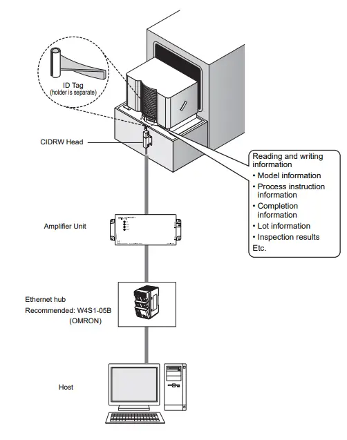
The CIDRW system writes data to, and reads data from, the carrier IDs (ID Tags) mounted on the carriers (FOUP) in semiconductor manufacturing processes without contacting these ID Tags. CIDRW is the abbreviation of Carrier ID Reader/Writer and this abbreviation is used throughout this manual. Reading and writing information such as models, process instructions, lots, and inspection results to and from ID Tags makes it possible to manage work instruction information from a host device.
Example: Management of information in semiconductor and wafer manufacturing processes
Features
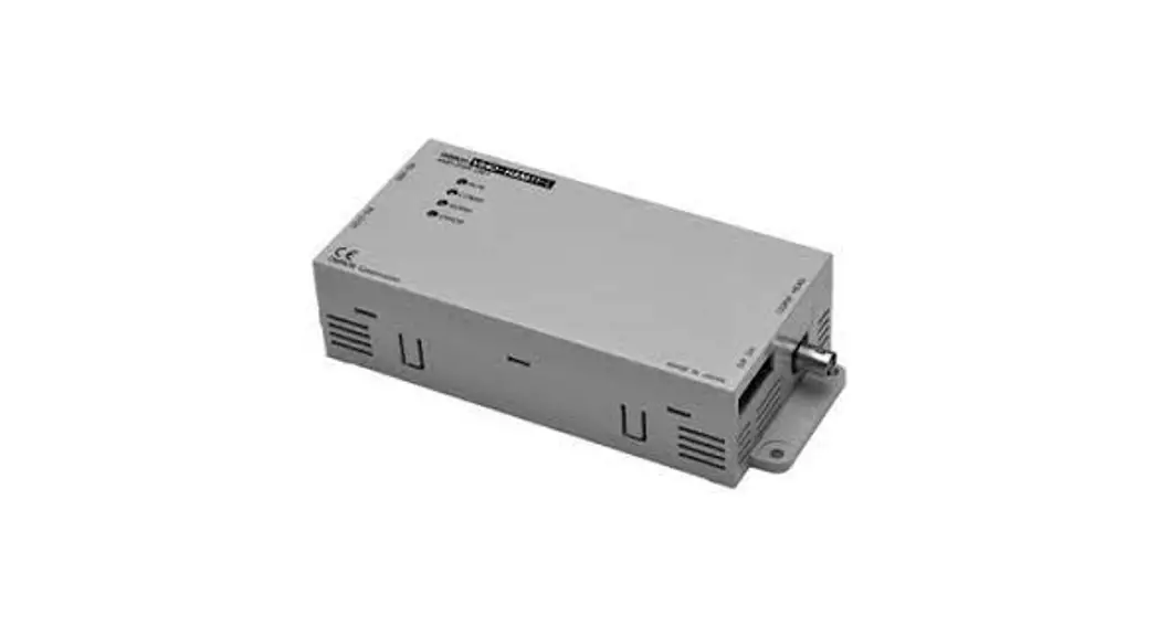
A V640-series CIDRW Head can be connected to a V640-HAM11-ETN-V2 or V640-HAM11-L-ETN-V2 Amplifier Unit to read and write ID Tags manufactured by Texas Instruments (TI). Reading and writing is performed according to commands from the host device.
- V640-HAM11-ETN-V2
The V640-HAM11-ETN-V2 Amplifier Unit is equipped with Ethernet. The host device is connected through a LAN cable and controls the Amplifier Units using TCP/IP. The Amplifier Units provide a Web browser function that allows communications to be set and status to be managed using simple command communications. - V640-HAM11-L-ETN-V2
The V640-HAM11-L-ETN-V2 Amplifier Unit is equipped with Ethernet and can be connected to a V640HS62 CIDRW Head to perform long-distance communications. The functions of the V640-HAM11-LETN-V2 Amplifier Unit are the same as those of the V640-HAM11-ETN-V2 Amplifier Unit.
System Configuration
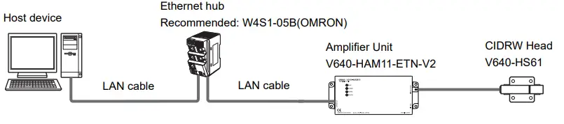
![]() V640-HAM11-ETN-V2
V640-HAM11-ETN-V2
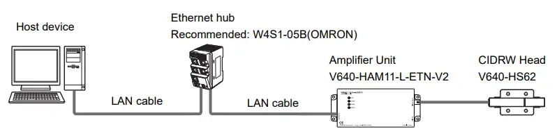
![]() V640-HAM11-L-ETN-V2
V640-HAM11-L-ETN-V2
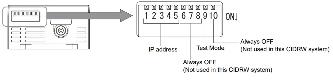
![]() If the IP address is set on the DIP switch, it will be in the form 192.168.1.. The subnet mask is always 255.255.255.0 The IP address of the Amplifier Unit can be either set on this DIP switch or the desired IP address can be set in ROM. If pins 1 to 5 on the DIP switch are all turned OFF, the IP address that is set in ROM will be used.
If the IP address is set on the DIP switch, it will be in the form 192.168.1.. The subnet mask is always 255.255.255.0 The IP address of the Amplifier Unit can be either set on this DIP switch or the desired IP address can be set in ROM. If pins 1 to 5 on the DIP switch are all turned OFF, the IP address that is set in ROM will be used.
Component Names and Functions![]() V640-HAM11-ETN-V2 and V640-HAM11-L-ETN-V2 Amplifier Units
V640-HAM11-ETN-V2 and V640-HAM11-L-ETN-V2 Amplifier Units
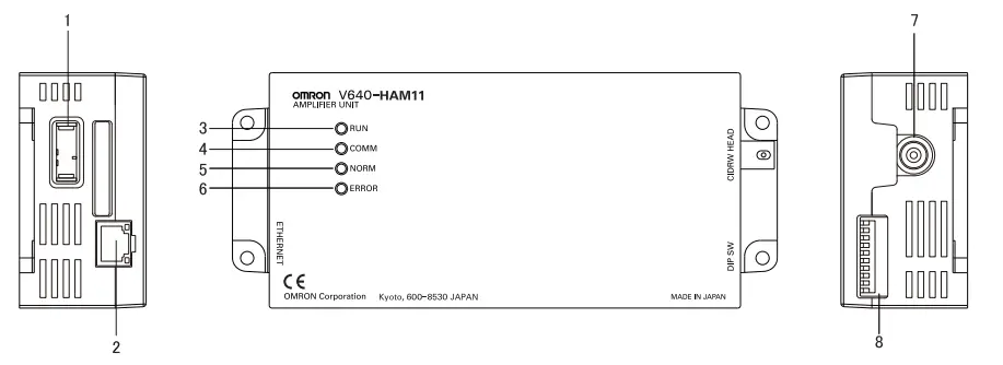
| No. | Name | Function |
| 1 | Dedicated power supply con- nector | Connect to the 24 VDC power supply. |
| 2 | Ethernet port | Connect to the host device through a LAN cable. |
| 3 | RUN indicator (green) | Turns ON when the Amplifier Unit is in normal operation. |
| 4 | COMM indicator (yellow) | Turns ON during communications with the host device or during communications with an ID Tag. |
| 5 | NORM indicator (green) | Turns ON when the communications finish with no error. |
| 6 | ERROR indicator (red) | Turns ON when an error occurs during communications with the host device, or during communications with an ID Tag. |
| 7 | CIDRW Head connection port | A CIDRW Head is connected here. The V640-HS61 CIDRW Head is used with the V640-HAM11-ETN-V2. The V640-HS62 CIDRW Head is used with the V640-HAM11-L-ETN-V2. |
| 8 | Setting DIP switches | Set the IP address and enable/disable the Test Mode with this DIP switch. |
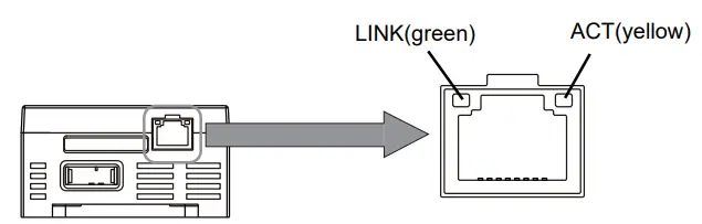
LINK—lights while linking normally.
ACT—lights when detects a carrier.
■ Functions
- NOISE MEASUREMENT
The levels of noise in the vicinity of the CIDRW Head are measured and the noise level is expressed numerically in the range “00” to “99. - Detecting for CIDRW Head status
You can confirm if the CIDRW Head is connected to the Amplifier Unit correctly. - Test Mode
Test Mode can be used to check communications between the ID Tags and Amplifier Units without connecting a host device. Communications with ID Tags are automatically performed every second and the communications results are displayed on the OPERATING indicator.
Set the Test Mode using the DIP switches on the side face of the Amplifier Unit.
After changing the DIP switch settings, restart the system. The new settings will not become effective until the system is restarted.
| Test Mode | DIP-SW | Description |
| 9 | ||
| Enabled | ON | Set the Test Mode and then restart the Amplifier Unit to make the setting effective. |
| Disabled | OFF |
![]() Refer to V640-HAM11-ETN-V2 and V640-HAM11-L-ETN-V2 Amplifier Units for information on the OPERATING indicator for communications results.
Refer to V640-HAM11-ETN-V2 and V640-HAM11-L-ETN-V2 Amplifier Units for information on the OPERATING indicator for communications results.![]() Always connect the CIDRW Head before operating the Amplifier Unit in Test Mode. If Test Mode is used without connecting a CIDRW Head, the ERROR inductor will light and Amplifier Unit operation will stop.
Always connect the CIDRW Head before operating the Amplifier Unit in Test Mode. If Test Mode is used without connecting a CIDRW Head, the ERROR inductor will light and Amplifier Unit operation will stop.![]() Commands from the host device are not accepted during operation in Test Mode. To end Test Mode, turn OFF the Test Mode pin on the DIP switch and restart the Amplifier Unit.
Commands from the host device are not accepted during operation in Test Mode. To end Test Mode, turn OFF the Test Mode pin on the DIP switch and restart the Amplifier Unit.
- Browser Interface
You can confirm the status of the Amplifier Unit or control the Amplifier Unit by using Browser Interface.
You can… - confirm the status of the Amplifier Unit
- set the Network Settings and Web Password
- communicate with ID tags
- measure the levels of noise
MEMO
![]() V640-HS61 and V640-HS62 CIDRW Heads
V640-HS61 and V640-HS62 CIDRW Heads
- V640-HS61
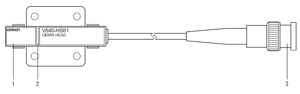
| No. | Name | Function |
| 1 | Antenna | Used to communicate with ID Tags. |
| 2 | Antenna center | This is the center of the communications area. |
| 3 | Connector | Connect to an Amplifier Unit. |
- V640-HS62
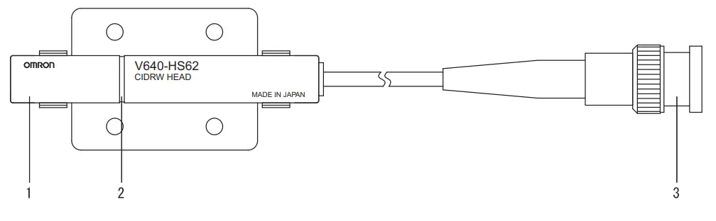
| No. | Name | Function |
| 1 | Antenna | Used to communicate with ID Tags. |
| 2 | Antenna center | This is the center of the communications area. |
| 3 | Connector | Connect to an Amplifier Unit. |
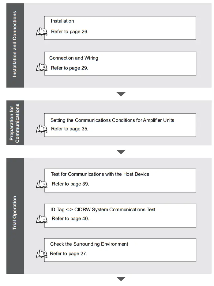
Flowchart for Getting Started

SECTION 2 Installation and Connections/Wiring
Installation![]() Amplifier Unit
Amplifier Unit
Use spring washers and flat washers with the four M4 screws when mounting the Amplifier Unit.
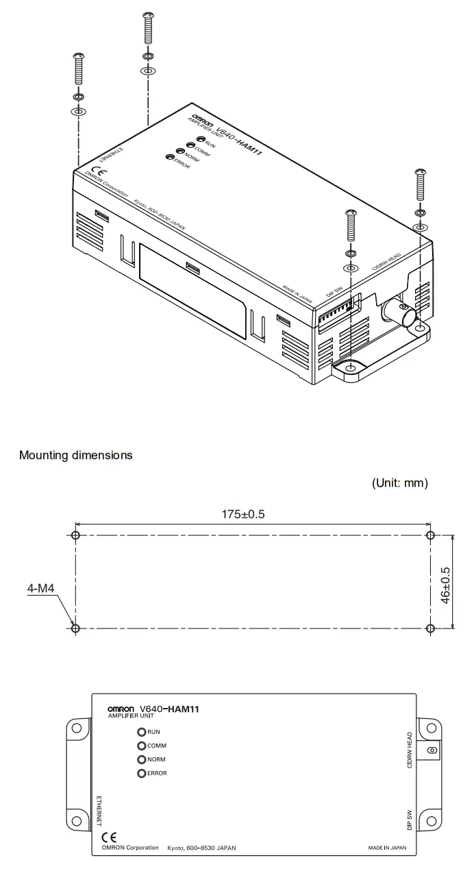
![]() Tighten the M4 screws with a torque not exceeding 1.2 N·m.
Tighten the M4 screws with a torque not exceeding 1.2 N·m.
![]() CIDRW Head
CIDRW Head
The area for communications with ID Tags varies substantially according to the installation orientations and the background conditions (metals, noise, etc.). Check the communications area before deciding the installation position.
For details on actual communications distances, see Characteristic Data depending on Conditions of Use in Appendix.
- Positional Relationship between the CIDRW Head and the ID Tag
The communications area differs according to the positional relationship during communications.
| Mounting orientation | Communications area (purely illustrative) | Explanation |
| Coaxial | 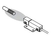 | The maximum communications area is obtained when the center lines of the CIDRW Head and the ID Tag coincide. |
| Parallel | 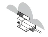 | The maximum communications area is obtained when the center point of the antenna on the CIDRW Controller is aligned with the center line of the ID Tag. |
| Vertical | 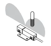 | When the center point of the antenna on the CIDRW Head is aligned with the center line of the ID Tag, the communications area is substantially reduced. |
- Data Reading and Writing
The communications distances for reading and writing are not the same; the distance is shorter for writing. Therefore, when data is to be both read and written, take the distance for writing as the reference distance when installing the CIDRW Head and the ID Tag. - Influence of Background Metal on ID Tag
Metals in the vicinity of the communications area will affect the range, making it smaller. - Influence of Noise
This CIDRW system uses a frequency of 134 kHz for communications with ID Tags. Equipment such as switching power supplies, inverters, servomotors, or monitors in the surrounding area will adversely affect communications, restricting the communications area.
![]() The noise levels in the vicinity of the CIDRW Head can be determined with the environmental NOISE MEASUREMENT command (applies only when SECS is not used)
The noise levels in the vicinity of the CIDRW Head can be determined with the environmental NOISE MEASUREMENT command (applies only when SECS is not used)
For details on the relationship between noise and communications distance, see Appendix
- Mounting
Use spring washers and flat washers with the four M3 screws when mounting a CIDRW Head.
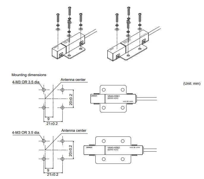
* The mounting dimensions are same between V640-HS61 and V640-HS62.![]() Tighten the M3 screws with a torque not exceeding 0.6 N·m.
Tighten the M3 screws with a torque not exceeding 0.6 N·m.
Connections and Wiring
![]() Amplifier Unit
Amplifier Unit
■ Connector for Connecting a CIDRW Head
- Align the pin on the connector with the channel in the cable connector and insert the cable connector.
Hold the fixed part of the connector while making this insertion.
- After inserting the connector fully home, turn the fixed part clockwise to lock it.
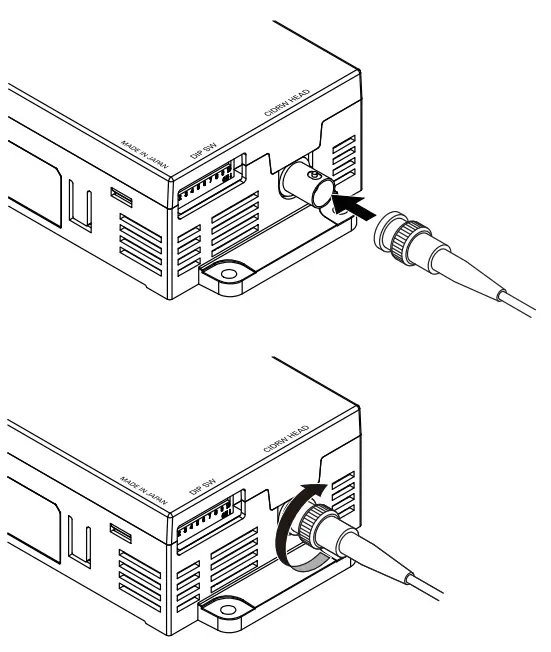
![]() Disconnecting the CIDRW head.
Disconnecting the CIDRW head.
Please pull it straight out after turn a connector counterclockwise and removing a lock.
If it is difficult to pull the connector out , press down on the Amplifier Unit while pulling on the connector.
Please do not pull a cable forcibly.
■ Ethernet Connector
- Hold the connector on the cable and insert it into the Ethernet connector on the Amplifier Unit.

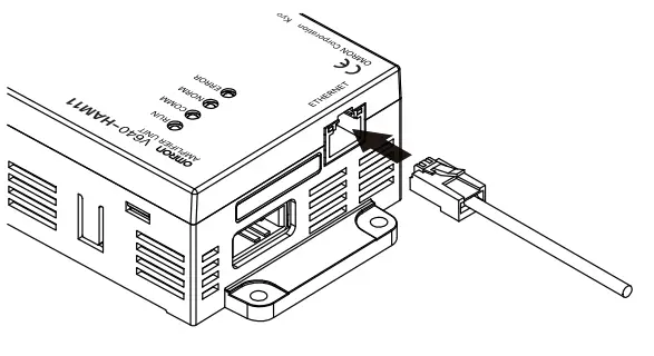
Press in the connector until it locks in place when connecting the Amplifier Unit to Ethernet, including when connecting it to a hub.
- Connector
The Amplifier Unit provides an auto-MDIX function that enables communications by connecting either a cross LAN cable or straight LAN cable.
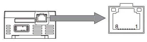
| Pin No. | Signal name | Description | I/O |
| 1 | TX_D+ | Send data + | Output |
| 2 | TX_D- | Send data – | Output |
| 3 | RX_D+ | Receive data + | Input |
| 4 | – | – | – |
| 5 | – | – | – |
| 6 | RX_D- | Receive data – | Input |
| 7 | – | – | – |
| 8 | – | – | – |
Recommended Ethernet HUB
| Manufacturer | Model | Type | Port |
| OMRON | W4S1-05B | switching hub | 5 |
![]() The shape and dimensions of plugs and jacks for Ethernet connectors are specified in ISO/IEC 8877:1992 (JIS X 5110:1996) To prevent faulty connections for connectors, the jack on the Amplifier Unit is designed so that non-standard plugs cannot be connected. If a commercially available plug cannot be connected, it may be non-standard.
The shape and dimensions of plugs and jacks for Ethernet connectors are specified in ISO/IEC 8877:1992 (JIS X 5110:1996) To prevent faulty connections for connectors, the jack on the Amplifier Unit is designed so that non-standard plugs cannot be connected. If a commercially available plug cannot be connected, it may be non-standard.![]() If you use a Hub in your network, please choose a Switching-type Hub (Recommended: W4S1-05B(OMRON)).
If you use a Hub in your network, please choose a Switching-type Hub (Recommended: W4S1-05B(OMRON)).
- Power Supply and Grounding Wires
Connect the power supply and grounding wires to the dedicated power supply connector.
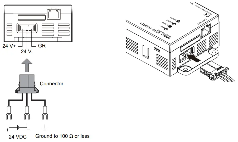
 The grounding wire should be connected to a ground exclusive to the Amplifier Unit. If the grounding wire is shared with another unit, or connected to a beam in a building, there may be adverse effects.
- Make the grounding point as close as possible and the length of the grounding wire used as short as possible.
- When using the Amplifier Unit in Europe, the connecting cable between the Amplifier Unit and the DC power supply must be 3 m or less.
- Dedicated Power Supply Connector
Prepare a V640-A90 (can be purchased as an accessory).
Contents of the V640-A90 set (accessory)
| Name | Quantity | When procured individually | |
| Manufacturer | Model | ||
| Power supply connector | One | Tyco Electronics | 1-178288-3 |
| Pins for power supply con- nector | Three | 175217-3 | |
| Connector for RS-485 port | One | Phoenix Contact | MSTB2.5/2-STF-5.08 |
* “Connector for RS-485 port“ is not able to use for the Amplifier Unit.
- Dedicated Power Supply Cable
Use an AWG20 to AWG24 cable.
Use a dedicated tool for crimping the cable to the connector pins.
Recommended Crimping Tool
| Manufacturer | Model |
| Tyco Electronics | 919601-1 |
- Power Supply
Use a power supply that satisfies the following conditions.
Recommended Product
| Manufacturer | Model | Output current | Input voltage |
| OMRON | S8VS-01524 | 24 VDC, 650 mA | 100 to 240 VAC |
*The maximum power consumption of the Amplifier Unit is 150 mA at 24 VDC(V640-HAM11-V3), 400 mA at 24 VDC(V640-HAM11-L). The inrush current, however, must be considered when selecting the power supply capacity. A power supply with an output of 650 mA min. at 24 VDC is recommended.
SECTION 3 Preparing for Communications
Set the IP address on the computer
The default IP addresses of the Amplifier Unit are given in the following table. Use these addresses to set the IP address on the computer.
This example changes the last part of the IP address to a value other than 200 (i.e., to 1 to 199 or 201 to 254).
Values of 0 and 255 cnnot be used.
- Default IP Address Settings of the Amplifier Unit
| Setting item | Default setting |
| IP address | 192.168.1.200 |
| Subnet mask | 255.255.255.0 |
![]() Setting the IP Address on the Computer with Windows 7/Windows 10
Setting the IP Address on the Computer with Windows 7/Windows 10
- Open the Control Panel, and select Network and Internet and then Network and Sharing Center.
- Select Change adapter settings and then right-click Local Area Connection.
- Right-click Local Area Connection and select Properties.
- Select Internet Protocol Version 4(TCP/IPv4) and then click the Properties Button.
- Select the Use the following IP address Option, make the following settings, and then click the OK Button. Change the last part of the IP address to a value other than 200 (i.e., to 1 to 199 or 201 to 254). Values of 0 and 255 cannot be used.
- Click the OK Button to colse the Internet Protocol Version 4(TCP/IPv4) Properties Dialog Box.
Setting the Communications Conditions for Amplifier Units
- Default network settings(IP Address and Subnet mask)
IP Address: 192.168.1.200 Subnet mask: 255.255.255.0 (Port: 7090) - If the IP address is set on the DIP switch, it will be in the form 192.168.1.. The subnet mask is always 255.255.255.0
- The IP address of the Amplifier Unit can be either set on this DIP switch or the desired IP address can be set in ROM. If pins 1 to 5 on the DIP switch are all turned OFF, the IP address that is set in ROM will be used.
![]() Setting the IP Address of the Amplifier Units using the DIP switches
Setting the IP Address of the Amplifier Units using the DIP switches
Set the communications conditions using the DIP switches on the side face of the Amplifier Unit. After changing the DIP switch settings, restart the system. The new settings will not become effective until the system is restarted.
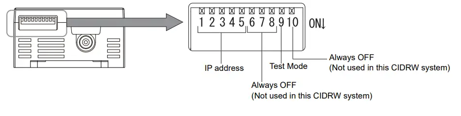
IP Address
| IP address | DIP switch | ||||
| 1 | 2 | 3 | 4 | 5 | |
| Setting in ROM | OFF | OFF | OFF | OFF | OFF |
| 192.168.1.1 | ON | OFF | OFF | OFF | OFF |
| 192.168.1.2 | OFF | ON | OFF | OFF | OFF |
| 192.168.1.3 | ON | ON | OFF | OFF | OFF |
| 192.168.1.4 | OFF | OFF | ON | OFF | OFF |
| 192.168.1.5 | ON | OFF | ON | OFF | OFF |
| 192.168.1.6 | OFF | ON | ON | OFF | OFF |
| 192.168.1.7 | ON | ON | ON | OFF | OFF |
| 192.168.1.8 | OFF | OFF | OFF | ON | OFF |
| 192.168.1.9 | ON | OFF | OFF | ON | OFF |
| 192.168.1.10 | OFF | ON | OFF | ON | OFF |
| 192.168.1.11 | ON | ON | OFF | ON | OFF |
| 192.168.1.12 | OFF | OFF | ON | ON | OFF |
| 192.168.1.13 | ON | OFF | ON | ON | OFF |
| 192.168.1.14 | OFF | ON | ON | ON | OFF |
| 192.168.1.15 | ON | ON | ON | ON | OFF |
| IP address | DIP switch | ||||
| 1 | 2 | 3 | 4 | 5 | |
| 192.168.1.16 | OFF | OFF | OFF | OFF | ON |
| 192.168.1.17 | ON | OFF | OFF | OFF | ON |
| 192.168.1.18 | OFF | ON | OFF | OFF | ON |
| 192.168.1.19 | ON | ON | OFF | OFF | ON |
| 192.168.1.20 | OFF | OFF | ON | OFF | ON |
| 192.168.1.21 | ON | OFF | ON | OFF | ON |
| 192.168.1.22 | OFF | ON | ON | OFF | ON |
| 192.168.1.23 | ON | ON | ON | OFF | ON |
| 192.168.1.24 | OFF | OFF | OFF | ON | ON |
| 192.168.1.25 | ON | OFF | OFF | ON | ON |
| 192.168.1.26 | OFF | ON | OFF | ON | ON |
| 192.168.1.27 | ON | ON | OFF | ON | ON |
| 192.168.1.28 | OFF | OFF | ON | ON | ON |
| 192.168.1.29 | ON | OFF | ON | ON | ON |
| 192.168.1.30 | OFF | ON | ON | ON | ON |
| 192.168.1.31 | ON | ON | ON | ON | ON |
![]() Setting the Communications Conditions of the Amplifier Units from a Web Browser
Setting the Communications Conditions of the Amplifier Units from a Web Browser
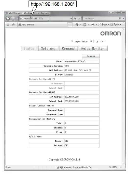
- Start the Web browser.
Enter the IP address of the Amplifier Units in the address field of the Web browser to display the Browser Operation Window.
Enter http://192.168.1.200 if you are using the default IP address.
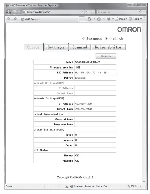
- Displays the Network Setting View.
Click the Settings Button at the upper of the Web Browser Operation Window. The Network settings View will be displayed.
 - Set the IP address of the Amplifier Units.
On the Network Settings View, enter the IP address, subnet mask, and then click the Save Button.
- Set the pins 1 to 5 on the DIP switch for Amplifier Unit are all turned OFF.
 The values are enabled when the Amplifier Unit is restarted.
 The Network settings View will be displayed.
![]() Setting the Communications Conditions of the Amplifier Units for Command from the Host Device
Setting the Communications Conditions of the Amplifier Units for Command from the Host Device
You can set the following items with a SET NETWORK command.
- IP address
- Subnet mask
Refer to SET NETWORK in SECTION 4 Reading from/Writing to ID Tags for the setting method for command from the host device.![]() When changing the Communications Conditions, restart the amplifier unit.
When changing the Communications Conditions, restart the amplifier unit.
The values are enabled when the Amplifier Unit is restarted.
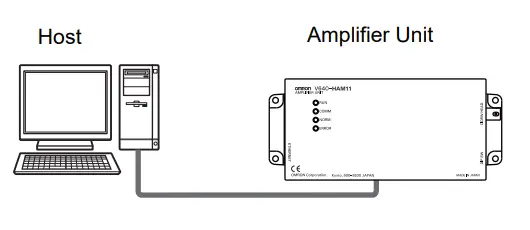
Communications Test![]() Communications Test with the Host Device
Communications Test with the Host Device
A communications test is performed to confirm that the host device and Amplifier Unit are connected correctly.![]() Refer to Host Communications Specifications.
Refer to Host Communications Specifications.
A test is preformed for the Amplifier Unit using the data 12345678.
Command
| Command code | Test data | CR | ||||||||
| Data 1 | Data 2 | Data 3 | Data 4 | |||||||
| 1 | 0 | 1 | 2 | 3 | 4 | 5 | 6 | 7 | 8 | 0Dh |
Response
| Response code | Test data | CR | ||||||||
| Data 1 | Data 2 | Data 3 | Data 4 | |||||||
| 0 | 0 | 1 | 2 | 3 | 4 | 5 | 6 | 7 | 8 | 0Dh |
![]() Communications Test between ID Tags and CIDRW System
Communications Test between ID Tags and CIDRW System
Send a command from the host device and check that normal communications with the ID Tag is possible. Place an ID Tag in the communications area of the CIDRW Head connected to the Amplifier Unit for which communications is to be tested.
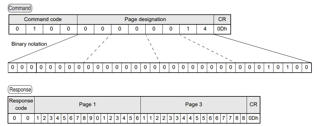
- READ
The data is read from pages 1 and 3 of the Amplifier Unit.
ID Tag contents
| Page 1 | 12h | 34h | 56h | 78h | 90h | 12h | 34h | 56h |
| Page 2 | ||||||||
| Page 3 | 11h | 22h | 33h | 44h | 55h | 66h | 77h | 88h |
| Page 4 |
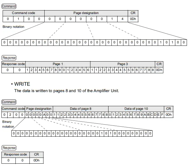
If the command ends normally, the contents of the ID Tag will be as follows:
| Page 8 | 11h | 22h | 33h | 44h | 55h | 66h | 77h | 88h |
| Page 9 | ||||||||
| Page 10 | 01h | 23h | 45h | 67h | 89h | ABh | CDh | EFh |
Command/Response Format
Command
| Command code | Parameter | CR | ||||||||
| 1 | … | n | ||||||||
| 0Dh | ||||||||||
Response
| Response code | Parameter | CR | ||||||
| 1 | ⋅ ⋅ ⋅ | n | ||||||
| 0Dh | ||||||||
![]() Command
Command
Command Code List
| Name | Value | Function | See |
| READ | 0100 | When this command is received, the system communicates with the ID Tag, and reads the specified page(s) of data. Any pages up to a maximum of 16 can be selected. | p.43 |
| WRITE | 0200 | When this command is received, the system communicates with the ID Tag, and writes the specified page(s) of data. Any pages up to a maximum of 16 can be selected. | p.44 |
| SAME WRITE | 0300 | When this command is received, the system communicates with the ID Tag, and writes the same data in page units to the specified pages. Up to 17 pages, which is the maximum number of pages for an ID Tag, can be specified. | p.46 |
| BYTE WRITE | 0400 | When this command is received the system communicates with the ID Tag, and writes data to the area specified by a first address and number of bytes. A maximum of 128 bytes can be specified. | p.47 |
| TEST | 10 | Sends received data to the host device. | p.48 |
| NAK | 12 | Sends the response made immediately before again. | p.49 |
| GET PARAMETER | 14 | Gets the model number, MAC address, or another parameter. | p.49 |
| GET LAST COM- MAND | 15 | Gets the command code of the last command that was executed. | p.54 |
| GET COMMUNICA- TIONS HISTORY | 16 | Gets the history of communications from when the power was turned ON (total num- ber of communications, total successful communications, and total number of failed communications). | p.54 |
| CLEAR COMMUNI- CATIONS HISTORY | 17 | Clears the communications history. | p.55 |
| NOISE MEASURE- MENT | 40 | Measures the noise in the vicinity of the CIDRW Head. | p.55 |
| RESET | 7F | Resets the Amplifier Unit. | p.56 |
| SET WEB PASS- WORD | A2 | Sets the Web password. | p.56 |
| SET NETWORK | A3 | Sets the network. | p.57 |
Response Code List
| Type | Response code | Name | Description |
| Normal end | 00 | Normal end | Command execution is completed normally. |
| Host commu- nications error | 14 | Format error | There is a mistake in the command format. (For example, the command code is undefined, or the page or address specification is inappropriate.) |
| Communica- tions error | 70 | Communications error | Noise or another hindrance occurs during communications with an ID Tag, and communications cannot be completed normally. |
| 71 | Verification error | Correct data cannot be written to an ID Tag. | |
| 72 | No Tag error | Either there is no ID Tag in front of the CIDRW Head, or the CIDRW Head is unable to detect the ID Tag due to environmental factors (e.g., noise). | |
| 7B | Outside write area error | A write operation was not completed normally because the ID Tag was in an area in which the ID Tag could be read but not written. | |
| 7E | ID system error (1) | The ID Tag is in a status where it cannot execute command processing. | |
| 7F | ID system error (2) | An inapplicable ID Tag has been used. | |
| CPU hardware error | 9A | Hardware error in CPU | An error occurred when writing to EEPROM. |
- READ
Reads any pages of data from the ID Tag. The maximum number of pages that can be read at one time is 16.

* Always specify 0. If you specify 1 an error (Response code: 14) will occur.
Parameter Description
| Parameter | Description |
| Page designation | Pages are specified by setting the bits corresponding to pages that are to be read to 1 and setting the other bits to 0, then converting the result to a hexadecimal character string. |
ID Tag Memory Maps
The response code (when normal: 00) and the data in the specified pages are returned in ascending order of page numbers.
Response
| Response code | Read data | CR | ||||||||||||||
| Page n | ⋅ ⋅ ⋅ | Page m (n<m) | ||||||||||||||
| Data 1 | ⋅ ⋅ ⋅ | Data 8 | Data 1 | ⋅ ⋅ ⋅ | Data 8 | |||||||||||
| 0 | 0 | 0Dh | ||||||||||||||
Example: Reading Data from Pages 1 and 3 of the Amplifier Unit.
Data Content of the ID Tag
| Page 1 | 12h | 34h | 56h | 78h | 90h | 12h | 34h | 56h |
| Page 2 | ||||||||
| Page 3 | 11h | 22h | 33h | 44h | 55h | 66h | 77h | 88h |
| Page 4 |
![]() If you send a “Read“ command that specified 1 to 2 page to a 1-page only ID Tag, the Amplifier Unit will response 2nd page data as all zero.
If you send a “Read“ command that specified 1 to 2 page to a 1-page only ID Tag, the Amplifier Unit will response 2nd page data as all zero.
- WRITE
Data is written in page units to the ID Tag. Any page(s) can be specified. It is possible to write to a maximum of 16 pages at one time.
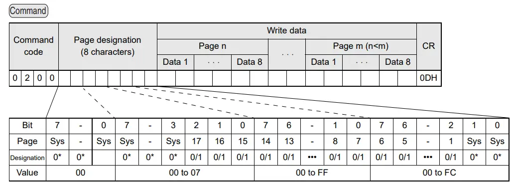
* Always specify 0. If you specify 1 an error (Response code: 14) will occur.
Parameter Description
| Parameter | Description |
| Page designation | Pages are specified by setting the bits corresponding to pages that are to be read to 1 and setting the other bits to 0, then converting the result to a hexadecimal character string. |
| Write data | The data to be written to the specified pages is specified in ascending order of page numbers. |
ID Tag Memory Maps
Response
The response code (when normal: 00) is returned.
| Response code | CR | |
| 0 | 0 | 0Dh |
Example: Writing Data to Pages 8 and 10 of the Amplifier Unit
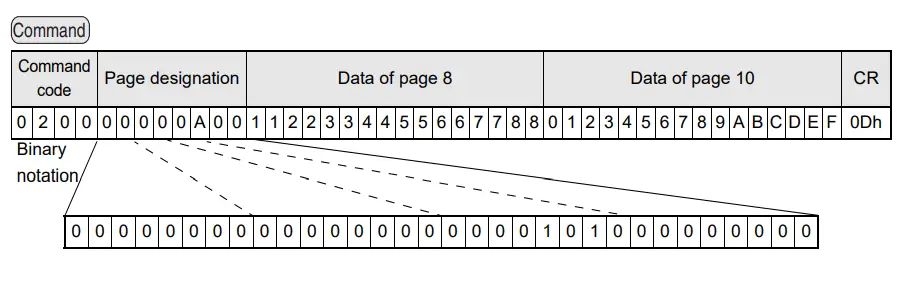
Response
| Response code | CR | |
| 0 | 0 | 0Dh |
The ID Tag status on normal completion is as shown below.
| Page 8 | 11h | 22h | 33h | 44h | 55h | 66h | 77h | 88h |
| Page 9 | ||||||||
| Page 10 | 01h | 23h | 45h | 67h | 89h | ABh | CDh | EFh |
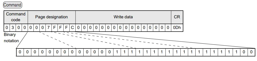
- SAME WRITE
This command writes the same data to multiple pages of an ID Tag. Any page(s) can be specified.
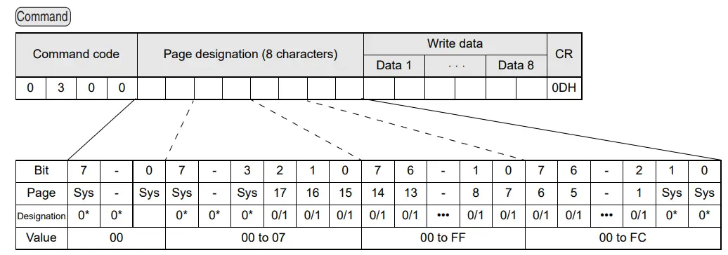
* Always specify 0. If you specify 1 an error (Response code: 14) will occur.
Parameter Description
| Parameter | Description |
| Page designation | Pages are specified by setting the bits corresponding to pages that are to be read to 1 and setting the other bits to 0, then converting the result to a hexadecimal character string. |
| Write data | Specify the write data. |
ID Tag Memory Maps
Response
The response code (when normal: 00) is returned.
| Response code | CR | |
| 0 | 0 | 0Dh |
Example: Clearing All Data on Pages 1 and 17 of the Amplifier Unit to 0
Response
| Response code | CR | |
| 0 | 0 | 0Dh |
- BYTE WRITE
This command writes data to any specified number of bytes starting from the address specified in the ID Tag. The maximum number of bytes that can be written at one time is 128.
Command
| Command code | First address | Write data | CR | |||||||||
| Data 1 | ••• | Data n | ||||||||||
| 0 | 4 | 0 | 0 | 0Dh | ||||||||
* Data number n = number of bytes written to (2-character units)
Parameter Description
| Parameter | Description |
| First address | Addresses can be specified in the range 00h to 87h. |
| Write data | Up to 128 bytes of write data, starting from the specified address, can be specified. |
ID Tag Memory Maps
Response
The response code (when normal: 00) is returned.
| Response code | CR | |
| 0 | 0 | 0Dh |
Example: Writing Two Bytes of Data to Address 05h of the Amplifier Unit
Command
| Command code | First address | Write data | CR | |||||||
| Data 1 | Data 2 | |||||||||
| 0 | 4 | 0 | 0 | 0 | 5 | 1 | 2 | 3 | 4 | 0Dh |
Response
| Response code | CR | |
| 0 | 0 | 0Dh |
The ID Tag status on normal completion is as shown below.
| Page 1 | 12h | 34h | ||||||
| Page 2 | ||||||||
- TEST
Performs a communications test on communications between the host device and Amplifier Unit.
When an Amplifier Unit receives a test command, it sends the response code and command test data to the host device as the response.
Command
| Command code | Test data | CR | ||||||
| Data 1 | ••• | Data n | ||||||
| 1 | 0 | 0Dh | ||||||
* Number of data n < 136 (2-character units)
Parameter Description
| Parameter | Description |
| Test data | The data to be sent in the test is specified with a hexadecimal value. (270 characters max.) However, note that odd numbers of characters cannot be used. |
Response
The response code (when normal: 00) and the received test data are returned.
| Response code | Test data | CR | ||||||
| Data 1 | ••• | Data n | ||||||
| 0 | 0 | 0Dh | ||||||
Example: Performing a Test for the Amplifier Unit Using the Data 12345678
Command
| Command code | Test data | CR | ||||||||
| Data 1 | Data 2 | Data 3 | Data 4 | |||||||
| 1 | 0 | 1 | 2 | 3 | 4 | 5 | 6 | 7 | 8 | 0Dh |
Response
| Response code | Test data | CR | ||||||||
| Data 1 | Data 2 | Data 3 | Data 4 | |||||||
| 0 | 0 | 1 | 2 | 3 | 4 | 5 | 6 | 7 | 8 | 0Dh |
- NAK
Sends the response made immediately before again.
Command
| Command code | CR | |
| 1 | 2 | 0Dh |
Response
Sends the response made immediately before again.![]() A response will not be returned if a NAK command is executed immediately after startup.
A response will not be returned if a NAK command is executed immediately after startup.
- GET PARAMETER
This command gets the model number, firmware version, or another parameter.
Command
| Command code | Parameter type | CR | ||
| 1 | 4 | 0Dh | ||
Parameter Description
| Parameter | Value | Description |
| Parameter type | 01 | Model number |
| 02 | Firmware version | |
| 03 | MAC address | |
| 10 | DIP switch enabled/disabled status | |
| 11 | IP address on DIP switch | |
| 12 | Subnet address on DIP switch | |
| 13 | IP address in ROM | |
| 14 | Subnet address in ROM | |
| 20 | Memory status | |
| 21 | Antenna connection status |
Response
The response code (00: normal) and received parameter value are returned.
| Response code | Parameter value | CR | ||||||
| 0 | 0 | 0Dh | ||||||
* The contents and length of the parameter value depend on the parameter type that is specified for the command.
Example 1: Getting the Model Number of Amplifier Unit
Command
| Command code | Parameter type | CR | ||
| 1 | 4 | 0 | 1 | 0Dh |
Response
The product model number is returned as an ASCII text string.
| Response code | Model number | CR | ||||||||||||||
| 0 | 0 | V | 6 | 4 | 0 | – | H | A | M | 1 | 1 | – | E | T | N | 0Dh |
Example 2: Getting the Firmware Version of Amplifier Unit
Command
| Command code | Parameter type | CR | ||
| 1 | 4 | 0 | 2 | 0Dh |
Response
The response code (00: normal) and firmware version are returned as a 4-digit decimal number.
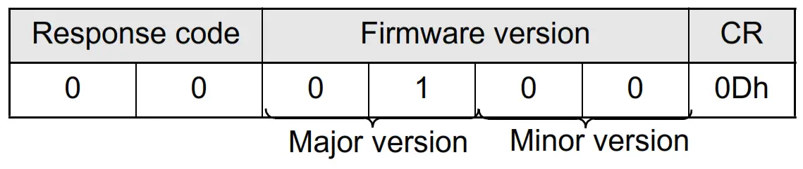
* The above response is for a firmware version of 1.00.
Example 3: Getting the MAC Address of Amplifier Unit
Command
| Command code | Parameter type | CR | ||
| 1 | 4 | 0 | 3 | 0Dh |
Response
The response code (00: normal) and MAC address are returned.
| Response code | MAC address | CR | ||||||||||||
| 0 | 0 | 0 | 0 | 1 | F | 1 | 6 | 1 | A | B | 9 | 8 | E | 0Dh |
* The above response is for a MAC address of 00:1F:16:1A:B9:8E.
Example 4: Checking If Network Settings on DIP Switch on Amplifier Unit Are Enabled or Disabled
Command
| Command code | Parameter type | CR | ||
| 1 | 4 | 1 | 0 | 0Dh |
Response
The response code (00: normal) and enabled/disabled status of the DIP switch network settings are returned.
| Response code | DIP switch enabled/disabled | CR | ||
| 0 | 0 | 0 | 1 | 0Dh |
* The above response is for when the DIP switch settings are enabled. The response will show 00 for disabled status.
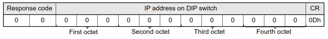
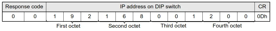
Example 5: Checking IP Address on DIP Switch on Amplifier Unit
Command
| Command code | Parameter type | CR | ||
| 1 | 4 | 1 | 1 | 0Dh |
Response
The response code (00: normal) and IP address on the DIP switch (decimal, four octets of 3 digits each) are returned.
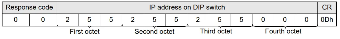
* The above response is for when the IP address on the DIP switch is 192.168.1.20.
* The following response will be returned if the DIP switch network settings are disabled.
Example 6: Checking the Subnet Mask on the DIP Switch of Amplifier Unit
Command
| Command code | Parameter type | CR | ||
| 1 | 4 | 1 | 2 | 0Dh |
Response
The response code (00: normal) and subnet mask (decimal, four octets of 3 digits each) are returned.
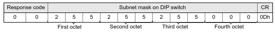
* The subnet mask is always 255.255.255.0 regardless of whether the DIP switch network settings are enabled or disabled.
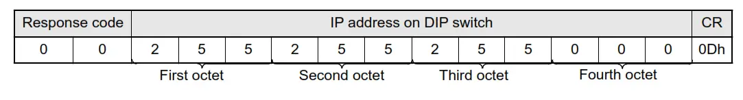
Example 7: Checking IP Address in ROM
Command
| Command code | Parameter type | CR | ||
| 1 | 4 | 1 | 3 | 0Dh |
Response
The response code (00: normal) and IP address in ROM (decimal, four octets of 3 digits each) are returned.
* The above response is for when the IP address in ROM is 192.168.1.200.
Example 8: Checking the Subnet Mask in ROM
Command
| Command code | Parameter type | CR | ||
| 1 | 4 | 1 | 4 | 0Dh |
Response
The response code (00: normal) and subnet mask (decimal, four octets of 3 digits each) are returned.
* The above response is for when the subnet mask in ROM is 255.255.255.0.
Example 9: Getting the Memory Status of Amplifier Unit
Command
| Command code | Parameter type | CR | ||
| 1 | 4 | 2 | 0 | 0Dh |
Response
The response code (00: normal) and memory check results for internal EEPROM are returned.
| Response code | Memory status | CR | ||
| 0 | 0 | 0 | 1 | 0Dh |
* “Memory status” will be if the memory is normal:”01”, and is error:”00”.
Example 10: Getting the Antenna Connection Status of Amplifier Unit
Command
| Command code | Parameter type | CR | ||
| 1 | 4 | 2 | 1 | 0Dh |
Response
The response code (00: normal) and Antenna connection status are returned.
| Response code | Antenna connec- tion status | CR | ||
| 0 | 0 | 0Dh | ||
* “Antenna connectionstatus” will be if the antenna is connected correctly:”01”, and is not correctly:”00”.
- GET LAST COMMAND
Gets the command code of the last command that was executed.
Command
| Command code | CR | |
| 1 | 5 | 0Dh |
Response
This command returns the command code of the last command that was executed.
When There Is a Previously Executed Command
| Response code | Command code | CR | ||||
| 0 | 0 | 0Dh | ||||
* The command code is given as two or four characters.
When There Is No Previously Executed Command
| Response code | Command code | CR | ||
| 0 | 0 | 0 | 0 | 0Dh |
- GET COMMUNICATIONS HISTORY
This command gets the history of communications from when the power was turned ON (total number of communications, total successful communications, and total number of failed communications).
Command
| Command code | CR | |
| 1 | 6 | 0Dh |
Response
This command returns the history of communications from when the power was turned ON. Four hexadecimal digits each are returned for the total number of communications, total number of successful communications, and total number of failed communications. If the total number of communications exceeds 65,535, all data in the communications history will be reset to 0.
| Response code | Total number of com- munications | Total number of suc- cessful communica- tions | Total number of failed communications | CR | ||||||||||
| 0 | 0 | 0Dh | ||||||||||||
Example 1: Getting the Communications History of Amplifier Unit
Command
| Command code | CR | |
| 1 | 6 | 0Dh |
Response
The following response is returned if there are 32,000 total communications, 30,000 successful communications, and 2,000 failed communications.
| Response code | Total number of com- munications | Total number of suc- cessful communica- tions | Total number of failed communications | CR | ||||||||||
| 0 | 0 | 7 | D | 0 | 0 | 7 | 5 | 3 | 0 | 0 | 7 | D | 0 | 0Dh |
- CLEAR COMMUNICATIONS HISTORY
This command clears the communications history.
Command
| Command code | CR | |
| 1 | 7 | 0Dh |
Response
| Response code | CR | |
| 0 | 0 | 0Dh |
- NOISE MEASUREMENT
The levels of noise in the vicinity of the CIDRW Head are measured and the noise level is expressed numerically in the range “00” to “99.”
Command
| Command code | CR | |
| 4 | 0 | 0Dh |
Response
The response code (when normal: 00) and the noise level “00” to “99” are returned.
| Response code | Noise level | CR | ||
| 0 | 0 | 0Dh | ||
Influence of background noise on communications distance
- RESET
All Amplifier Unit processing is stopped, and the initial status is re-established.
Command
| Command code | CR | |
| 7 | F | 0Dh |
Response
There is no response to this command.
- SET WEB PASSWORD
This command sets the Web password.
If you set a password, a Password entry window will be displayed when you start the browser window.
Command
When the Password Is Not Set
| Command code | Password (1 to 16 characters) | CR | ||||||||||||||||
| A | 2 | 0Dh | ||||||||||||||||
* Only the following characters can be used in passwords: 0 to 9, a to z, and A to Z. If any other characters are used, error 14 will occur.
* If the password is not between 1 and 16 characters long, error 14 will occur.
When the Password Is Not Set
| Command code | CR | |
| A | 2 | 0Dh |
Response
| Response code | CR | |
| 0 | 0 | 0Dh |
![]() Never turn OFF the power supply to the Amplifier Unit before a response is received from the Amplifier Unit for this command. Doing so may damage the Amplifier Unit.
Never turn OFF the power supply to the Amplifier Unit before a response is received from the Amplifier Unit for this command. Doing so may damage the Amplifier Unit.![]() The values are enabled when the Amplifier Unit is restarted.
The values are enabled when the Amplifier Unit is restarted.
- SET NETWORK
This command sets the IP address and subnet mask in ROM.
Command
| Command code | First octet | Second octet | Third octet | Fourth octet | CR | |||||||||
| A | 3 | 0Dh | ||||||||||||
Parameter Description
| Parameter | Description |
| Type | IP address setting: 00 Subnet mask setting: 01 |
| First to fourth octets | The address is set in decimal in four octets of three characters each. |
Response
| Response code | CR | |
| 0 | 0 | 0Dh |
* If an error occurs when writing to EEPROM, error 9A will be returned.
![]() Never turn OFF the power supply to the Amplifier Unit before a response is received from the Amplifier Unit for this command. Doing so may damage the Amplifier Unit.
Never turn OFF the power supply to the Amplifier Unit before a response is received from the Amplifier Unit for this command. Doing so may damage the Amplifier Unit.![]() The values are enabled when the Amplifier Unit is restarted.
The values are enabled when the Amplifier Unit is restarted.
SECTION 5 Browser Interface
Browser Operation Windows
To operate an Amplifier Unit from a browser, connect the Ethernet cables, start a browser on the computer, and specify the IP address of the Amplifier Unit as the URL. The Browser Window will be displayed. The Status Window will be displayed first. (If a Web password is set, the Status Window will be displayed after the Password Entry Window.) Menu buttons to move to the other windows are provided at the top of the window. Click a menu button to move to another window.![]() You can use the Windows application “V640 Utility Tool” which has the same functions as the browser interface. Download the “V640 Utility Tool” on your regional OMRON website. If you use “V640 Utility Tool”, you don’t need Java Plug-in.
You can use the Windows application “V640 Utility Tool” which has the same functions as the browser interface. Download the “V640 Utility Tool” on your regional OMRON website. If you use “V640 Utility Tool”, you don’t need Java Plug-in.
Precautions
- The system requirements to use the Web browser are as follows:
- Windows 7, Windows 8.1, or Windows 10 with Internet Explorer 8 or higher
- The combination of the firmware version and the JRE version
| JRE version Amplifier Units firmware version | Java 5 | Java 6 | Java 7 | Java 8 | ||
| Up to Update64 | Update65 to Update201 | Update211 or later *1 | ||||
| Ver1.00 | Available | Available | Available | Available | Not available*2 | Not available*2 |
| Ver1.01 | Not available | Available | Available | Available | Available | Available |
*1. Commercial license is required fore Java 8 Update 211 (April 16, 2019)
*2. Java8 Update65 (October 5, 2015) or later can not be connected.![]() There is case where WEB browser can not be used in a combination of the firmware version of Amplifier Unit and the JRE version.
There is case where WEB browser can not be used in a combination of the firmware version of Amplifier Unit and the JRE version.
Refer to the table above, please use the JRE version that was appropriate for your Amplifier Unit.
Java software can be downloaded from the following URL: https://www.oracle.com/java/technologies/downloads/archive/
(*URL is as of October 2022 and may change in the future.)
(Java and other trademarks that contain “Java” are the registered trademarks of Oracle Corporation or its related companies.)
- Before starting the Browser Window, make sure that the Amplifier Unit is not executing a command from terminal software or another source. The Amplifier Unit must be in idling status. If the Browser Window is started while the Amplifier Unit is executing a command, responses will not be returned for the commands sent from the terminal software or Browser Window.
- Access is possible from only one browser at a time. If the Amplifier Unit is accessed from another browser (B) while it is connected to a browser (A), the control right will move to browser B.
![]() Before you begin the Browser Interface
Before you begin the Browser Interface
- Connect the PC to the Amplifier Unit through the LAN cable.
- Turn on of the Amplifier Unit.
- Start the browser (ex.Internet Explorer).
- Input the IP Address of the Amplifier Unit in the URL column.
- The Amplifier Unit browser screen will be displayed.
Window Configuration
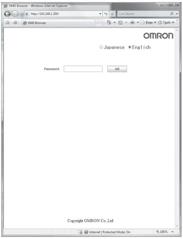
![]() Password Entry Window
Password Entry Window
If a Web password is set in the Amplifier Unit, the Password Entry Window will be displayed before the Browser Window is displayed. Enter the password and click the OK Button in this window. If the password is correct, the Status Window will be displayed.
The following characters can be used for the password: 0 to 9, a to z, and A to Z.
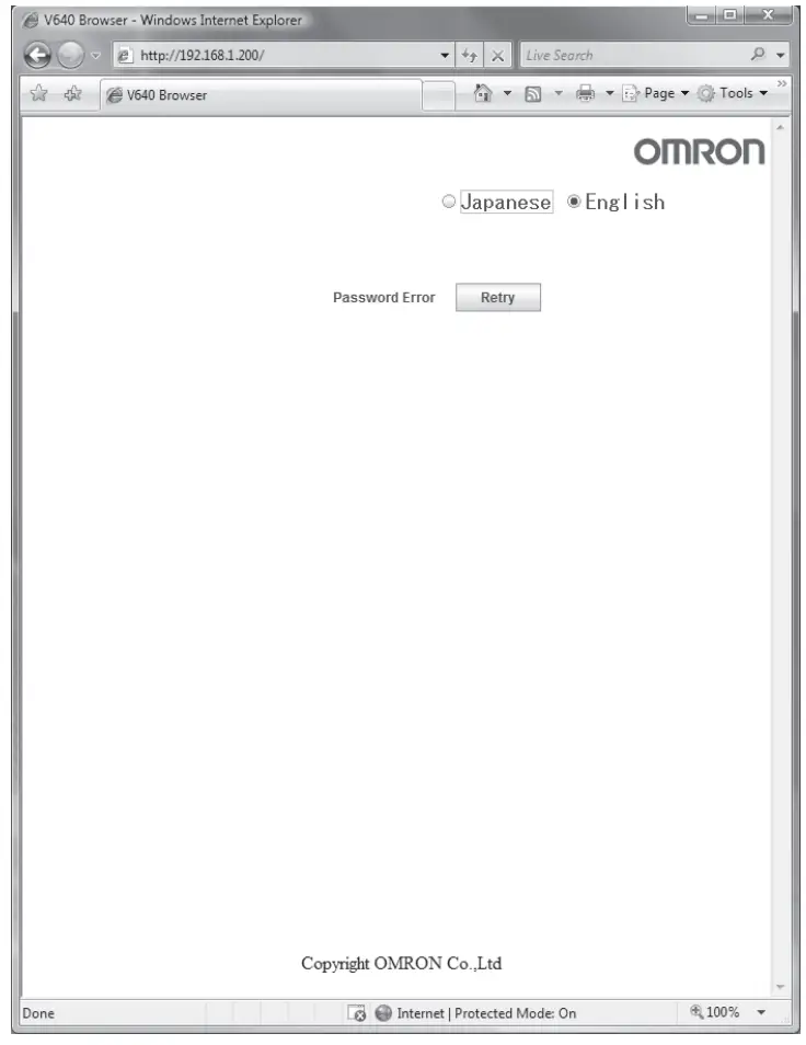
If the password is not correct, the following window will be displayed.
Click the Retry Button. The Password Entry Window will be displayed again.
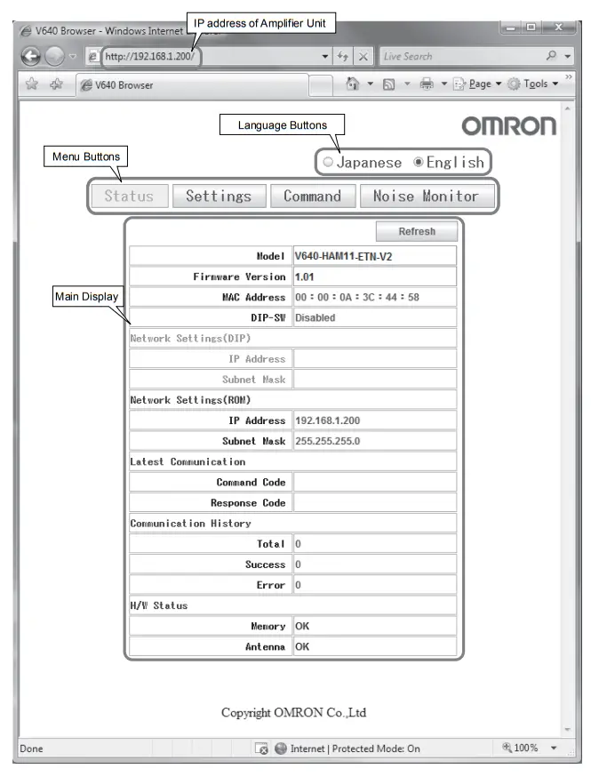
![]() Status Window
Status Window
The Status Window displays the model number, firmware version, MAC address, and other information on the Amplifier Unit so that you can check it. Click the Refresh Button at the top of the window to update the displayed information (latest communication, communication history, and H/W status).
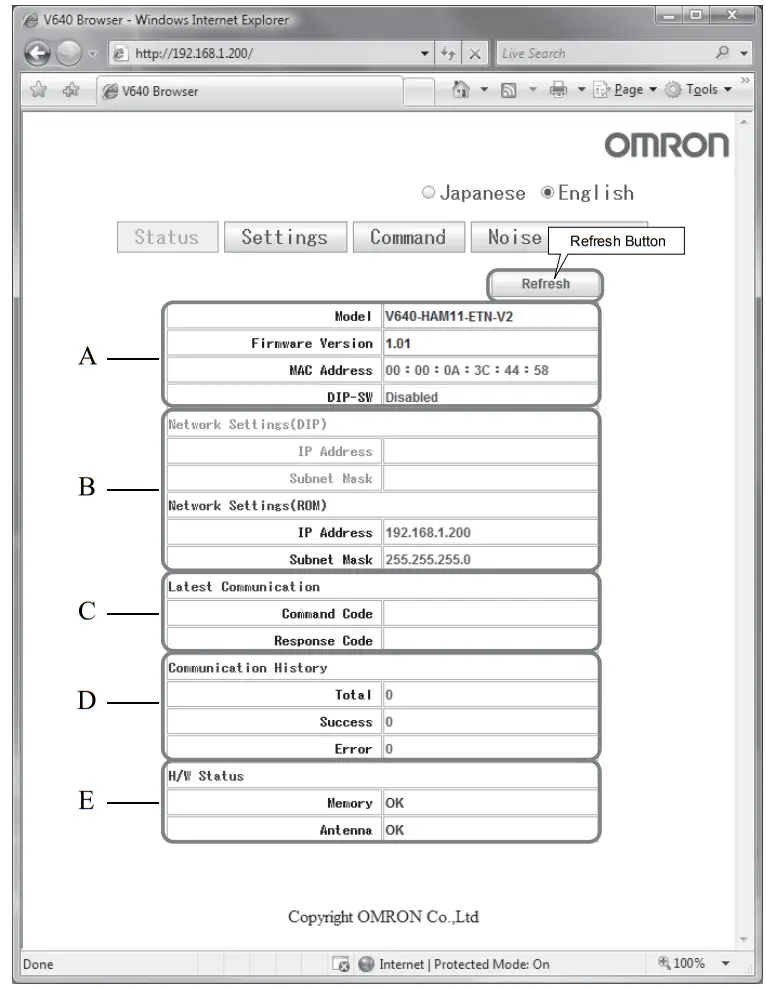
A Amplifier Unit Information
| Item | Description | Comments |
| Model | The product model number is displayed. | |
| Firmware Version | The firmware version is displayed. | |
| MAC Address | The MAC address is displayed. | |
| DIP-SW | “Enabled” is displayed if the Amplifier Unit is set to use the IP address that is set on the DIP switch. “Disabled” is displayed if the Amplifier Unit is set to use the IP address that is set in ROM. |
B Network Setting Information
| Item | Description | Comments |
| Network Settings(DIP) IP Address Subnet Mask | If the Amplifier Unit is set to use the IP address that is set on the DIP switch, this item is displayed in blue, and the IP address and subnet mask of the Amplifier Unit are displayed. | If the Amplifier Unit is set to use the IP address that is set on the DIP switch, this item is grayed out. |
| Network Settings(ROM) IP Address Subnet Mask | If the Amplifier Unit is set to use the IP address that is set in ROM, this item is displayed in blue, and the IP address and subnet mask of the Amplifier Unit are displayed. | If the Amplifier Unit is set to use the IP address that is set in ROM, this item is grayed out. |
C Last Command Information
| Item | Description | Comments |
| Latest Communication Command Code | The last command code that was executed and the last response code that was returned by the Amplifier Unit are displayed. | Nothing is displayed if a command has not been executed since the Amplifier Unit was started. |
D Communications History Information
| Item | Description | Comments |
| Communication History | History information on communications with the ID Tags is displayed. |
|
| Total | Total number of communications | |
| Success | Total number of successful communications | |
| Error | Total number of failed communications |
E Hardware Information
| Item | Description | Comments |
| H/W Status Memory Antenna | Hardware information is displayed. “Error” is displayed if a memory error was detected during the memory check at startup. “Error” is displayed if an error is detected in the CID Head that is con- nected to the Amplifier Unit (or if a CID Head is not connected). | “OK” is displayed for nor- mal status. |
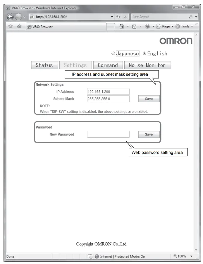
![]() Setting Window
Setting Window
The network settings (IP address and subnet mask) of the Amplifier Unit and the Web password can be set in the Setting Window. The values that are set are enabled when the Amplifier Unit is restarted.
If the Save Button is clicked when the password box is empty, the Web password will be cleared. In this state, the browser interface can be used without entering the Web password.
The following characters can be used for the Web password: 0 to 9, a to z, and A to Z.
![]() Never turn OFF the power supply to the Amplifier Unit before a response is received after clicking the Save Button.
Never turn OFF the power supply to the Amplifier Unit before a response is received after clicking the Save Button.
Doing so may damage the Amplifier Unit.![]() Command Window
Command Window
The Command Window can be used to communicate with ID Tags. The Command Window has two tab pages: “CID R/W” and “V640 Command.”
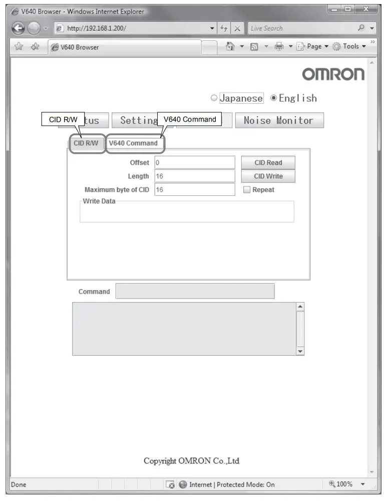
![]() CID R/W Tab Page
CID R/W Tab Page
The CID R/W Tab Page allows you to read or write ID Tag data by specifying the offset, length, and maximum bytes of CID. If writing is executed, you must also specify the write data.
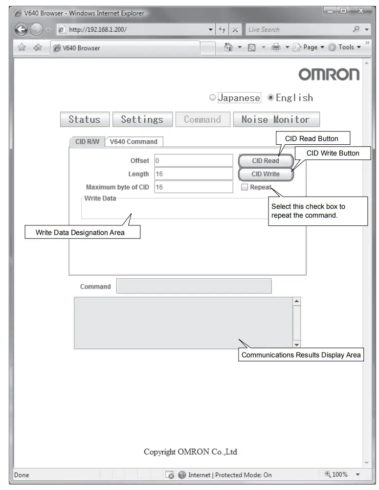
| Item | Description | Comments |
| Offset | Specify the CID offset between 0 and 15 bytes. | |
| Length | Specify the CID length between 1 and 16 bytes. | |
| Maximum byte of CID | Specify the maximum CID length between 1 and 16 bytes. | |
| Write Data | For the write data, specify only the number of bytes for the specified length. | Specify only visible ASCII characters. |
For example, the results display would be as shown below if a CID read was executed with an offset of 0, a length of 16, and a maximum bytes of CID of 16.
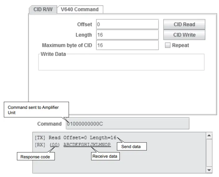
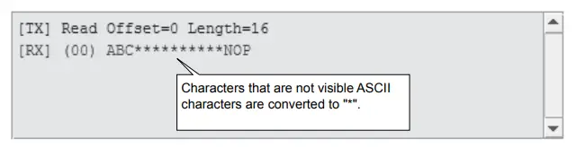
Only visible ASCII characters can be used to read and write data on the CID R/W Tab Page. If characters that are not visible ASCII characters are detected for a CID read,
they will be converted to aster- isks (*).
![]() V640 Command Tab Page
V640 Command Tab Page
The V640 Command Tab Page allows you to read and write data according to the command format of the Amplifier Unit
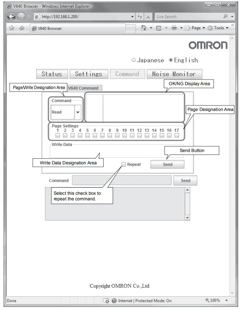
- Page/Write Designation Area
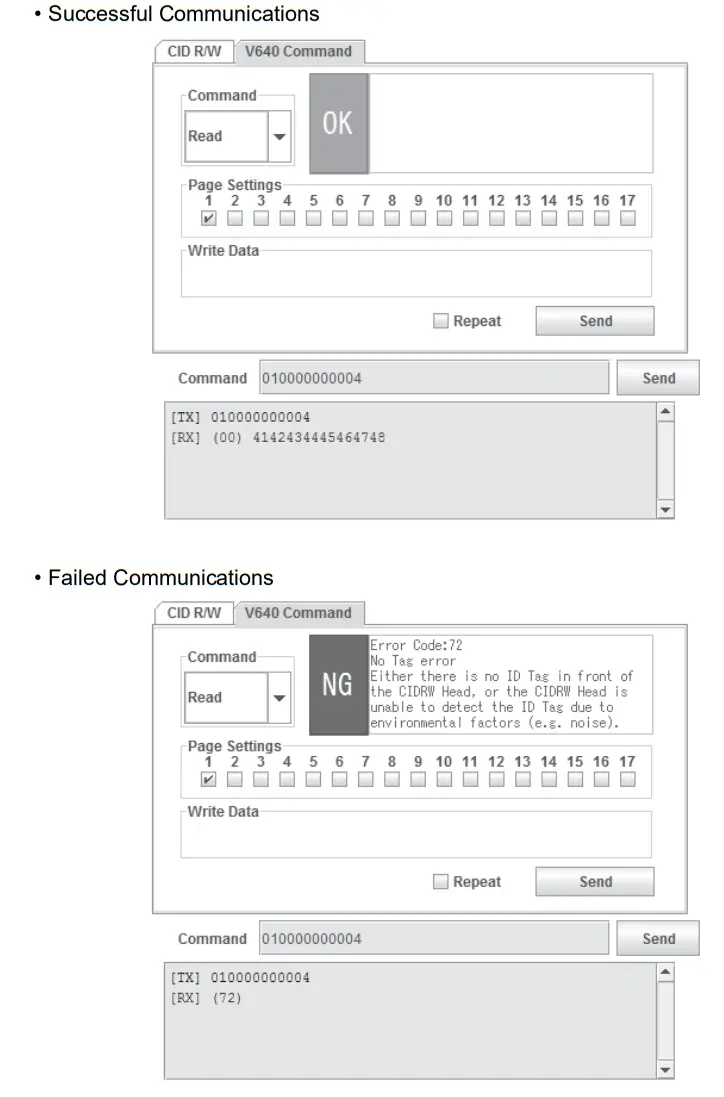
Select Read or Write in the Page/Write Designation Area. - OK/NG Display Area
The command execution results will be displayed as “OK” or “NG” in the OK/NG Display Area. If “NG” is displayed, information on the error will be displayed.
- Page Designation Area
Select the check boxes to specify the pages to be read or written. - Write Data Designation Area
When writing data, specify the data to write to the ID Tag as a hexadecimal string. Specify 16 characters for each page that you specify in the Page Designation Area.
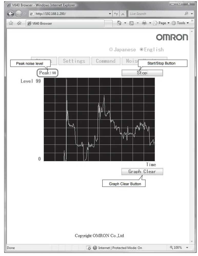
![]() Noise Measurement Window
Noise Measurement Window
The Noise Measurement Window allows you to continuously send the NOISE MEASUREMENT command to the Amplifier Unit and display the results in realtime. The horizontal axis gives the time and the vertical axis gives the noise level (0 to 99).
SECTION 6 Troubleshooting
Troubleshooting
Errors are indicated by the presence or absence of a response to an Amplifier Unit command, and by the indicators.
![]() List of Error Messages
List of Error Messages
| Type | Response code | Name | Description |
| Host communi- cations error | 14 | Format error | There is a mistake in the command format. (For example, the com- mand portion is undefined, or the page or address specification is inappropriate.) |
| Communications error between the CIDRW Head and ID Tag | 70 | Communications error | Noise or another hindrance has occurred during communications with an ID Tag, and communications cannot be completed normally. |
| 71 | Verification error | Correct data cannot be written to an ID Tag. | |
| 72 | No Tag error | Either there is no ID Tag in front of the CIDRW Head, or the CIDRW Head is unable to detect the ID Tag due to environmental factors (e.g., noise). | |
| 7B | Outside write area error | The ID Tag is at a position where reading is possible but writing is not, so writing does not complete normally. | |
| 7E | ID system error (1) | The ID Tag is in a status where it cannot execute the command pro- cessing. | |
| 7F | ID system error (2) | An inapplicable ID Tag has been used. | |
| CPU hardware error | 9A | Hardware error in CPU | An error occurred when writing to EEPROM. |
![]() Amplifier Unit Indicators
Amplifier Unit Indicators
| Name | Indications |
| RUN (green) | Turns ON when the Amplifier Unit is in normal operation. |
| COMM (orange) | Turns ON during communications with the host device or during communications with an ID Tag. |
| NORM (green) | Turns ON when the communications finish with no error. |
| ERROR (red) | Turns ON when an error occurs during communications with the host device, or during communications with an ID Tag. |
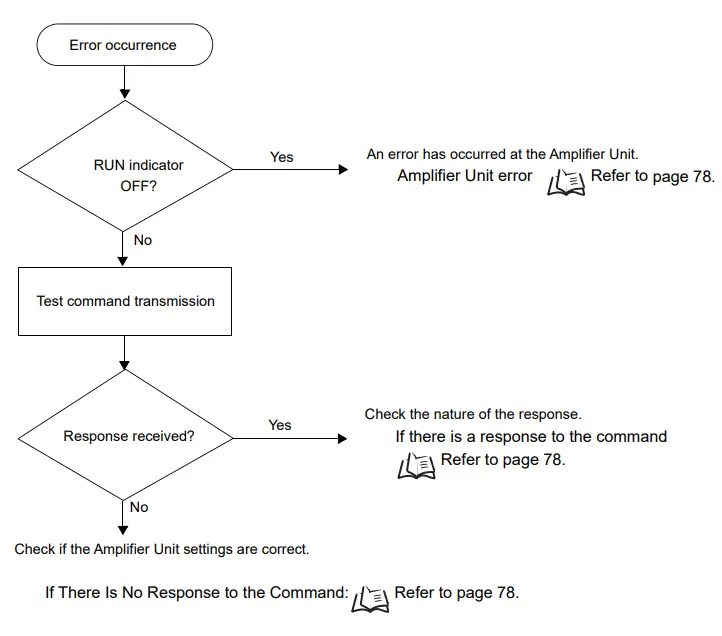
![]() Operation Check Flowchart
Operation Check Flowchart
- From Installation to Trial Operation
Errors are indicated by whether or not a response to the test command is received and by the status of the Amplifier Unit indicators.
- If the Test Command Was Received Normally:
Indicators
| RUN | COMM | NORM | ERROR |
| (Lights once) |
|
|
Response Code for the Response
| Type | Response code | Function |
| Normal | 00 | The command was received normally. |
- Amplifier Unit Error
Check the status of the indicators after transmission of the test command.
After taking appropriate corrective action, restart the Amplifier Unit, send the test command again and check again.
| RUN | COMM | NORM | ERROR | Main check points |
| — | The Amplifier Unit may be damaged. | |||
| — | • Influence of background noise (change installation position) • Amplifier Unit power supply If the error cannot be resolved after checking, the Amplifier Unit may be damaged. | |||
- If There Is No Response to the Command:
Check the status of the indicators after transmission of the test command.
After taking appropriate corrective action, restart the Amplifier Unit, send the test command again and check again.
| RUN | COMM | NORM | ERROR | Main check points |
| • Pleas establish the connection between the PC and the Ampli- fier Unit again, because the TCP/IP connection may be dis- connected. • Connection and wiring of the cable between the host device and Amplifier Unit • Routing of each cable (influence of background noise) If the error cannot be resolved after checking, the Amplifier Unit may be damaged. | ||||
| (Lights once) | • Connection and wiring of the cable between the host device and Amplifier Unit • Routing of the cables (influence of background noise) • There is a mistake in the command format (number of charac- ters, character code, etc.) |
- If There Is a Response to the Command:
Check the status of the indicators after transmission of the test command.
After taking appropriate corrective action, restart the Amplifier Unit, send the test command again and check again.
| RUN | COMM | NORM | ERROR | Main check points |
| (Lights once) | There is a mistake in the command format (number of charac- ters, character code, etc.). | |||
| By an interruption of the power supply, the memory may be dam- aged. |
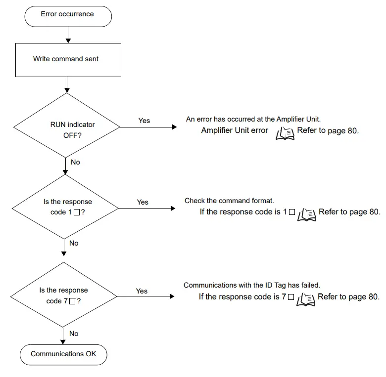
- From Trial Operation to Communications
Errors are indicated by the status of the indicators after transmission of the write command, and by the response code of the response.
- If the ID Tag Was Processed Normally:
Indicators
| RUN | COMM | NORM | ERROR |
| (Lights once) | (Lights once) |
|
Response Code for the Response
| Type | Response code | Function |
| Normal | 00 | The ID Tag was processed normally. |
![]() If there is no response to the write command, refer to the From Installation to Trial Operation, Operation Check Flowchart.
If there is no response to the write command, refer to the From Installation to Trial Operation, Operation Check Flowchart.
- Amplifier Unit Error
Check the status of the indicators after transmission of the command. After taking appropriate corrective action, send the write command again and check again.
| RUN | COMM | NORM | ERROR | Main check points |
| — (If RUN is OFF, the status of the other indica- tors can be ignored.) | • Influence of background noise (Change installation position) • Amplifier Unit power supply If the error cannot be resolved by checking the two points above, the Amplifier Unit may be damaged. | |||
- If the Response Code is 1
 :
:
There is a host device communications error.
Check the status of the indicators and the response code of the response after transmission of the
command. After taking appropriate corrective action, send the write command again and check again.
| RUN | COMM | NORM | ERROR |
(Lights once) |
| Response code | Main check points |
| 14 | Command format (Command code, page designation, address designation, processed data volume, etc.) |
- If the Response Code is 7 :
There is a communications error in communications between the CIDRW Head and ID Tag.
Check the status of the indicators and the response code of the response after transmission of the command. After taking appropriate corrective action, send the write command again and check again.
| RUN | COMM | NORM | ERROR |
| (Lights once) | (Lights once) |
| Response code | Main check points |
| 70 | • Background noise levels of the CIDRW Head (Check the surroundings with the environmental noise level measurement function) • Distance to another CIDRW Head • Influence of background noise (Change installation position) • Please check the Antenna Connection Status by using “GET PARAMETER“ command. If the error cannot be resolved after checking, the Amplifier Unit may be damaged. |
| 71 | • ID Tag overwrite life (Replace the ID Tag) • Environment of use of the ID Tags (ID Tag breakage due to use in unanticipated ways) |
| 72 | • Connection to the CIDRW Head • Distance between the ID Tag and CIDRW Head • CIDRW Head background noise levels (Check the surroundings with the environmental noise level measurement function) • Distance to another CIDRW Head • Please check the Antenna Connection Status by using “GET PARAMETER“ command. |
| 7B | • Distance between the ID Tag and CIDRW Head • Background noise levels of the CIDRW Head (Check the surroundings with the environmental noise level measurement function) • Distance to another CIDRW Head • Influence of background noise (Change installation position) |
| 7E | • Type/specifications of the ID Tags used • Settings of the ID Tags used (The ID Tag lock function is used.*) • Environment of use of the ID Tags (ID Tag breakage due to use in unanticipated ways) |
| 7F |
* The ID Tag has a lock function, but the Amplifier Unit has no function for locking an ID Tag.
- Other Troubleshooting
- Operating in Test Mode
Always connect the CIDRW Head before operating the Amplifier Unit in Test Mode. If Test Mode is used with abnormal CIDRW Head cable or without connecting a CIDRW Head, the ERROR indicator will light and Amplifier Unit operation will stop.
| RUN | COMM | NORM | ERROR | Main check points |
| • Please check that the CIDRW Head is connected correctly. If the error cannot be resolved after checking, the Amplifier Unit or the CIDRW Head may be damaged. |
- When a browser screen is not displayed
Please confirm the following items. - Please confirm whether the network settings is correct.
- Please confirm JRE (version 5.0 or newer) is installed in the host.
- Please confirm whether setting of Proxy does not have an error.
Cannot Display the Web Browser Operation Window
This section describes countermeasures when you cannot access the Amplifier Unit Web browser interface (i.e., when you cannot display the operation window).
Only countermeasures that have been confirmed by OMRON are provided. They may not solve all possible problems. Contact your OMRON representative if you have problems that cannot be solved.
![]() Problem
Problem
When the Web browser Amplifier Unit interface is used to display the Web operation window, the OMRON logo is displayed and an error message is displayed instead of the operation menu.
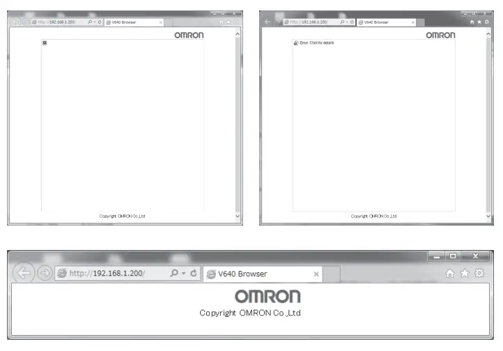
![]() Solution
Solution
Check the message that appears when you try to start the Web browser interface, and then perform the corresponding procedure.
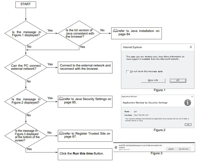
![]() Java installation
Java installation
Install Java bit version (64-bit or 32-bit) decided by the following flow.
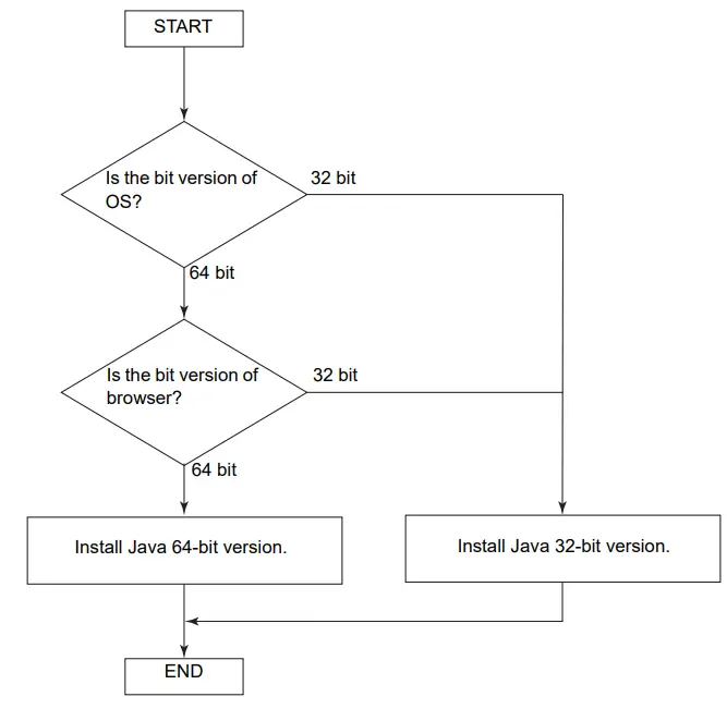
How to check the bit version of Windows 7 /Windows 10.
- Click Start menu and select Computer.
- Click Properties from the displayed item.
- In the System window, system type display the bits version of OS.
32-bit operating system or 64-bit operating system.
![]() Java Security Settings
Java Security Settings
(1) Open the Control Panel and click the Java Icon.
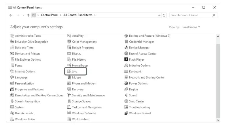
(2) Click the Security Tab and change the security level from High to Medium.
* If the security settings are not displayed, refer to Java Security Settings Are Not Displayed.
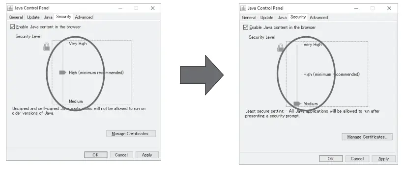
![]() This procedure will reduce the security verification performed for execution of Java applications and therefore it may affect the execution of other Java applications.
This procedure will reduce the security verification performed for execution of Java applications and therefore it may affect the execution of other Java applications.
(3) Restart the web browser and access the IP address of the Amplifier Unit again.
* The following warning message displayed at the first time. Click the Run Button.
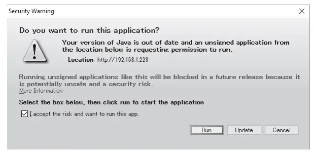
![]() Java Security Settings Are Not Displayed
Java Security Settings Are Not Displayed
This section describes the countermeasure when the exception site list is not displayed and operation is not possible.
If the tab page to change Java security settings does not appear and you cannot change the settings when you select the Security Tab in step 2 of the procedure in Countermeasure for Security Settings, use the following procedure.
(1) Open the Control Panel and uninstall all Java programs.
(2) After you uninstall all of the programs, go to the following website and install Java.
https://www.oracle.com/technetwork/java/archive-139210.html
(*URL is as of April 2019 and may change in the future.)
Refer to Browser Operation Windows in SECTION 5 Browser Interface for Java versions that can be used.![]() Java security features have been improved for the most recent version of Java, so the same problem may occur.
Java security features have been improved for the most recent version of Java, so the same problem may occur.
![]() Register Trusted Site
Register Trusted Site
- Open the Web browser, click the Tools menu and select Internet Options.
- Click the Security Tab, select Trusted sites and click Sites button.
 Java security features have been improved for the most recent version of Java, so the same problem may occur.
 - In the Add this Web site to the zone box, enter the IP address of the target Amplifier Unit, and then click Add button.
http://”IP address of target device”ex) http://192.168.1.200/
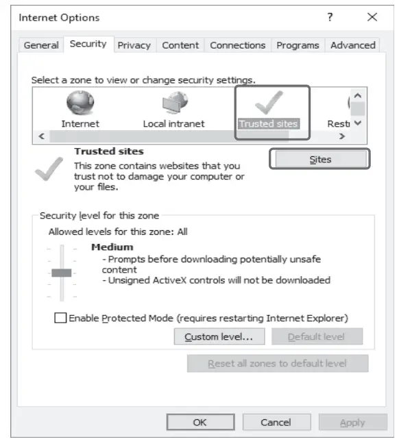
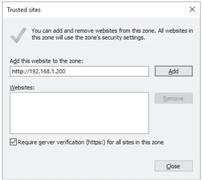
![]() Countermeasures for Other Problems
Countermeasures for Other Problems
- Open the Control Panel and click the Java Icon.

- Click the Settings Button in the Temporary Internet Files Area on the General Tab Page.

- Select the Keep temporary files on my computer Check Box and click the Delete Files Button.

- Click the OK Button.

- When the files have been deleted, click the OK Button and close all windows. Then, restart the Web browser and connect to the Amplifier Unit again.
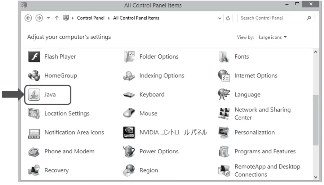
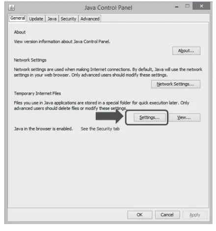
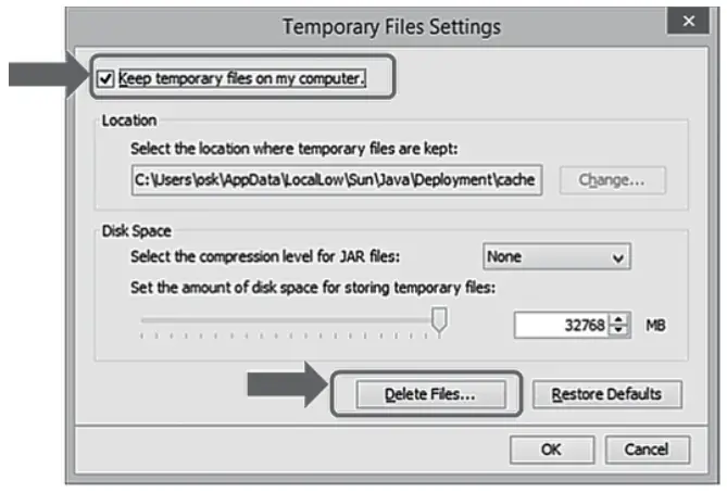
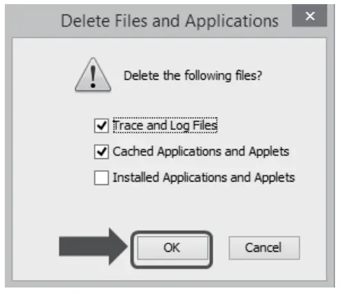
SECTION 7 Appendix
Specifications and Dimensions
Amplifier Units
V640-HAM11-ETN-V2 and V640-HAM11-L-ETN-V2
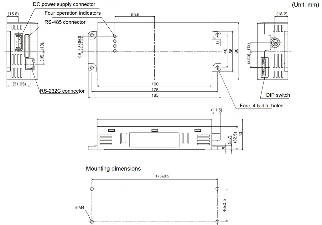
| Item | Specifications | |
| V640-HAM11-ETN-V2 | V640-HAM11-L-ETN-V2 | |
| Power supply voltage | 24 VDC +10% -15% | |
| Current consumption | 150 mA max. | 400 mA max. |
| Degree of protection | IP20 (IEC60529: 2001) | |
| Ambient temperature | Operating: 0 to +40°C Storage: -15 to +65°C (with no icing) | |
| Ambient humidity | Operating/Storage: 35% to 85% (with no condensation) | |
| Insulation resistance | 20 ML min.(with 100 VDC megohmmeter) between power supply terminals and the frame ground terminal | |
| Dielectric strength | 1,000 VAC (50/60 Hz for 1 min.) leak current consumption 5 mA max. between both power supply terminals and the frame ground terminal | |
| Vibration resistance | 10 to 150 Hz, double amplitude: 0.20 mm, Max. Acceleration: 15 m/s2 with 10 sweeps for 8 min. each in 3 directions | |
| Shock resistance | 150 m/s2, 3 times each in 6directions | |
| Ground | Ground to 100 L or less. | |
| Case material | PC/ABS resin | |
| Dimensions | 80´185´43 mm (W´D´H, excluding protruding parts) | |
| Mass | Approx. 250 g | |
| Frequency | 134.2 kHz | |
| Rediated magnetic field strength | maximum 35 dBmA/m at 10 meters (fixed) | |
| Environmental pollution degree | Degree 2 | |
| Over voltage category | Category I | |
| Mounting method | Secured with four M4 screws. (tightening torque: 1.2N·M) | |
| CIDRW Head | V640-HS61 | V640-HS62 |
- Host Communications Specifications
| Item | Description |
| Compliant standards | 10Base-T and 100Base-TX |
| Protocol | TCP/IP |
| IP Address | • If the IP address is set on the DIP switch, it will be in the form 192.168.1.□□□. The subnet mask is always 255.255.255.0 • The IP address of the Amplifier Unit can be either set on this DIP switch or the desired IP address can be set in ROM. If pins 1 to 5 on the DIP switch are all turned OFF, the IP address that is set in ROM will be used. Default network settings IP Address: 192.168.1.200, Subnet mask: 255.255.255.0 (Pins 1 to 5 on the DIP switch are all turned OFF) |
| Applicable port | TCP/IP: port 7090 |
| MTU | 1,500 bytes |
![]() Access to an Amplifier Unit is possible from only one host device at a time. If a host device (A) is connected to an Ampli-fier Unit and another host device (B) connects to the Amplifier Unit, the connection between host device A and the Amplifier Unit will be automatically broken and host device B will have the control right.
Access to an Amplifier Unit is possible from only one host device at a time. If a host device (A) is connected to an Ampli-fier Unit and another host device (B) connects to the Amplifier Unit, the connection between host device A and the Amplifier Unit will be automatically broken and host device B will have the control right.![]() When the connection between a PC and a Amplifier Units have been disconnected, an Amplifier Unit can reopen communication from a PC again by establishing a connection.
When the connection between a PC and a Amplifier Units have been disconnected, an Amplifier Unit can reopen communication from a PC again by establishing a connection.![]() Communications with the ID Tag will be aborted if the Ethernet cable is disconnected or the connection is broken while the Amplifier Unit is communicating with an ID Tag.
Communications with the ID Tag will be aborted if the Ethernet cable is disconnected or the connection is broken while the Amplifier Unit is communicating with an ID Tag.
CIDRW Heads V640-HS61
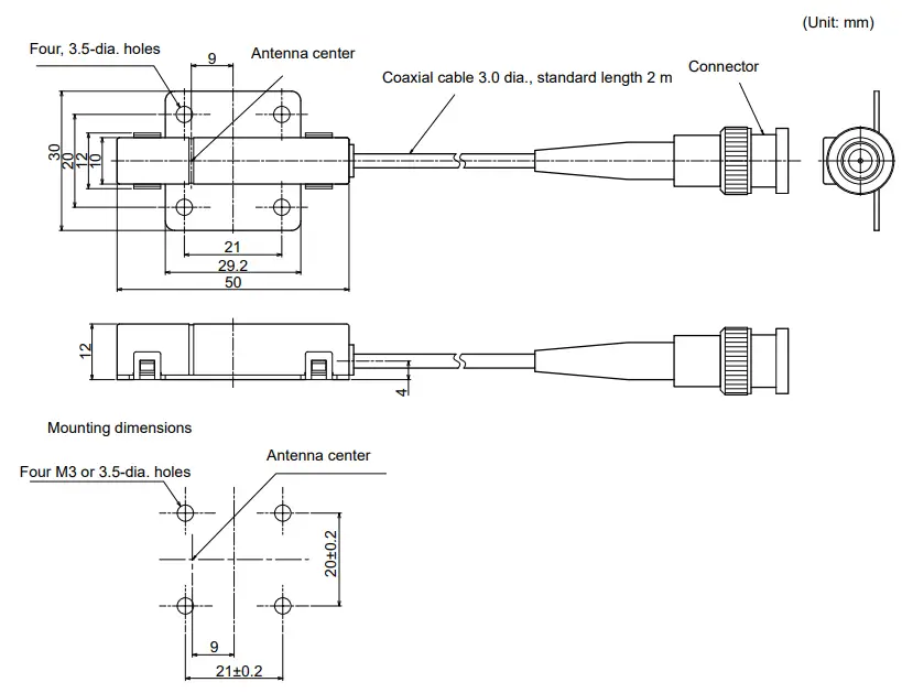
| Item | Specifications |
| Transmission frequency | 134 kHz |
| Ambient temperature | Operating: 0 to +40°C Storage: -15 to +65°C (with no icing) |
| Ambient humidity | Operating/Storage: 35% to 85% (with no condensation) |
| Degree of protection | IP60 (IEC60529) |
| Insulation resistance | 20 ML min. between all terminals and the case (100 VDC M) |
| Dielectric strength | Leak current not to exceed 5 mA on application of 1000 VAC (50/60 Hz for 1 minute) between all terminals and the case |
| Vibration resistance | Frequency: 10 to 150 Hz; double amplitude: 0.20 mm; acceleration: 15 m/s2 for 8 minutes, 10 times each in X, Y, and Z directions |
| Shock resistance | Shock of 150 m/s2 in X, Y, and Z directions, 3 times each for 18 repetitions |
| Casing material | ABS/epoxy resin Stainless steel mount |
| Weight | Approx. 70 g |
| Cable length | 2 m |
| Cable specification | 3-mm-dia. coaxial cable |
V640-HS62
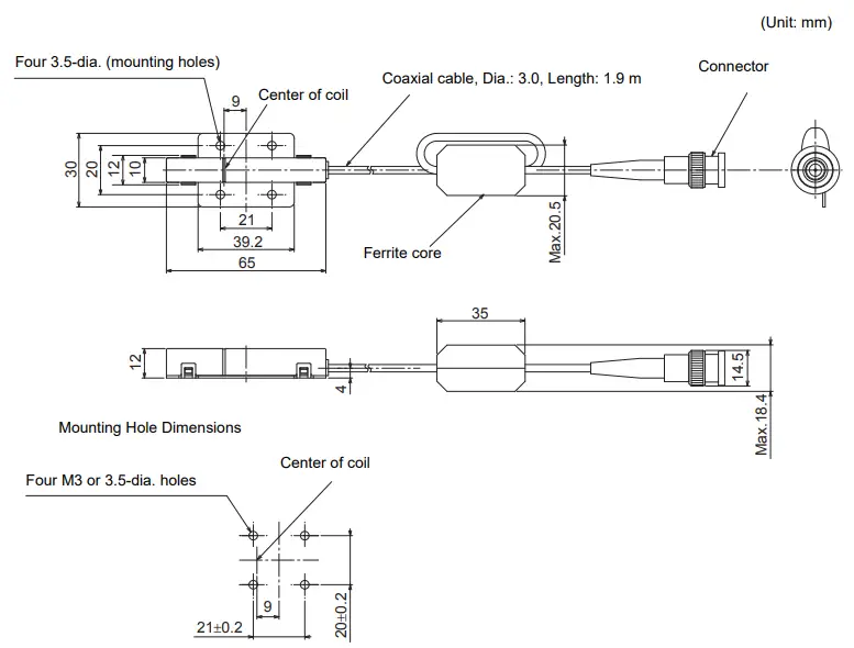
| Item | Specifications |
| Transmission frequency | 134 kHz |
| Ambient temperature | Operating: 0 to +40°C Storage: -15 to +65°C (with no icing) |
| Ambient humidity | Operating/Storage: 35% to 85% (with no condensation) |
| Degree of protection | IP60 (IEC60529) |
| Insulation resistance | 20 ML min. between all terminals and the case (100 VDC M) |
| Dielectric strength | Leak current not to exceed 5 mA on application of 1000 VAC (50/60 Hz for 1 minute) between all terminals and the case |
| Vibration resistance | Frequency: 10 to 150 Hz; double amplitude: 0.20 mm; acceleration: 15 m/s2 for 8 minutes, 10 times each in X, Y, and Z directions |
| Shock resistance | Shock of 150 m/s2 in X, Y, and Z directions, 3 times each for 18 repetitions |
| Casing material | ABS/epoxy resin Stainless steel mount |
| Weight | Approx. 100 g |
| Cable length | 1.9 m |
| Cable specification | 3-mm-dia. coaxial cable |
Connection Examples
![]() V640-HAM11-ETN-V2
V640-HAM11-ETN-V2
Connect the host device and Amplifier Unit using a LAN cable.
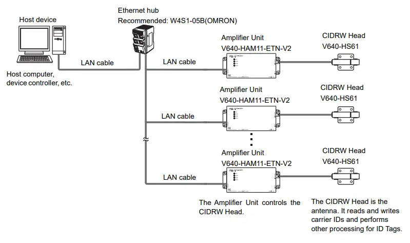
![]() V640-HAM11-L-ETN-V2
V640-HAM11-L-ETN-V2
Connect the host device and Amplifier Unit using a LAN cable.
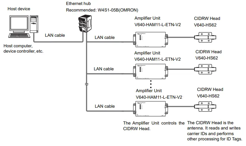
![]() Characteristic Data According to Conditions of Use
Characteristic Data According to Conditions of Use
Maps of Communications Areas (Reference Only)
The figures given below for communications areas (communications distances) are reference values only. The maps of communications areas will vary according to the ID Tags that you use, the background metals, the ambient noise, the effects of temperature and so on, and should be thoroughly confirmed on installation. The direction of the ID Tags will affect communications performance. Check the direction of the coils in the ID Tags before using the ID Tags.
- V640-HAM11-ETN-V2
- Coaxial Mounting (RI-TRP-DR2B-30)
- READ
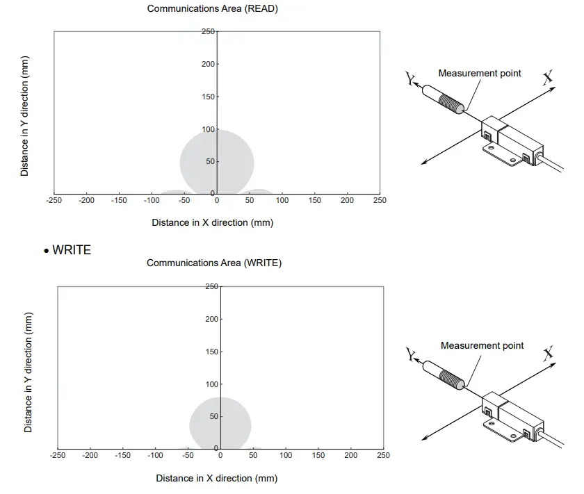
- Coaxial Mounting (RI-TRP-DR2B-30)
- READ
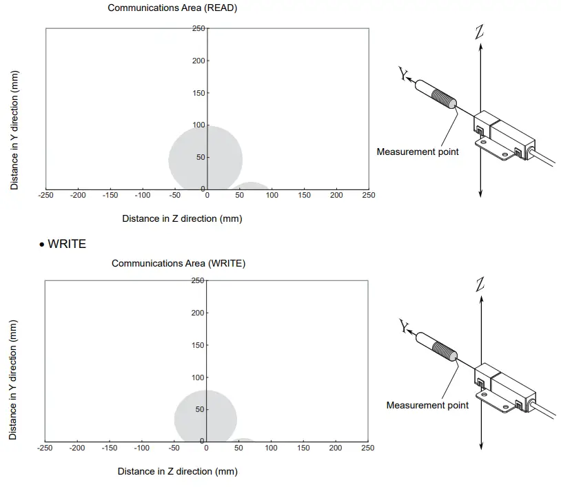
- Parallel Mounting (RI-TRP-DR2B-30)
- READ
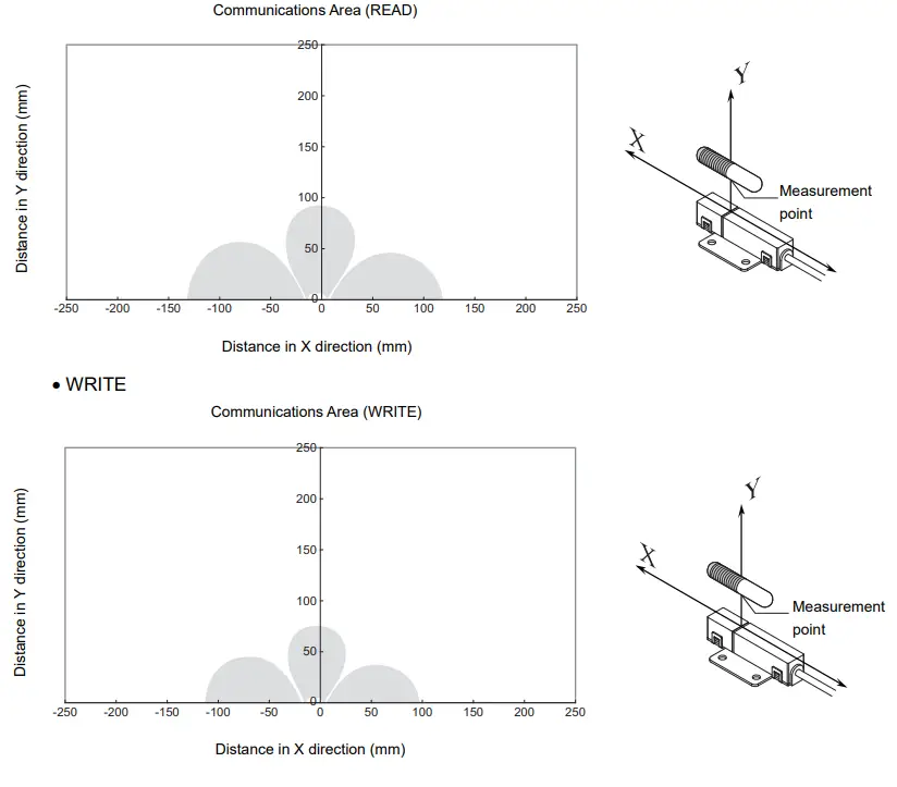
- Parallel Mounting (RI-TRP-DR2B-30)
- READ
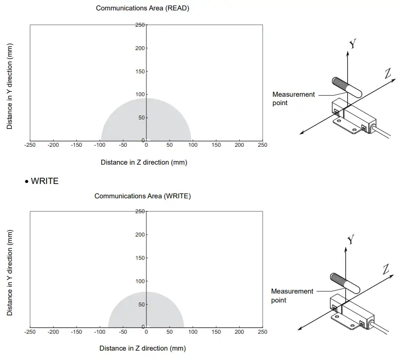
- Vertical Mounting (RI-TRP-DR2B-30)
- READ
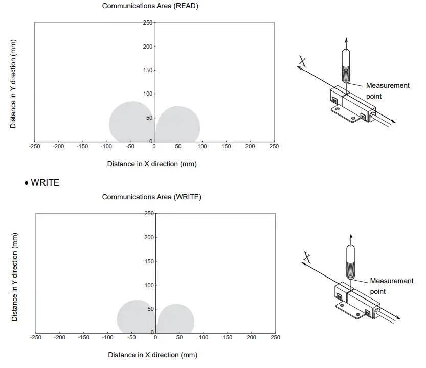
- Vertical Mounting (RI-TRP-DR2B-30)
- READ
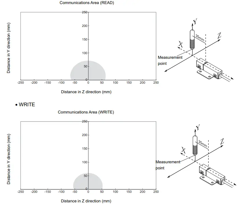
- Coaxial Mounting (RI-TRP-WR2B)
- READ
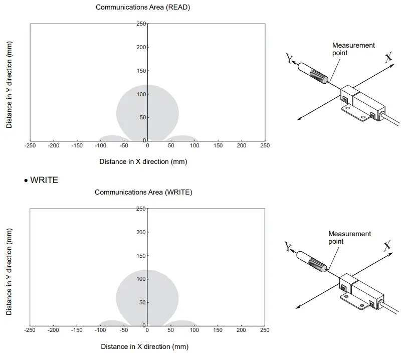
- Coaxial Mounting (RI-TRP-WR2B)
- READ
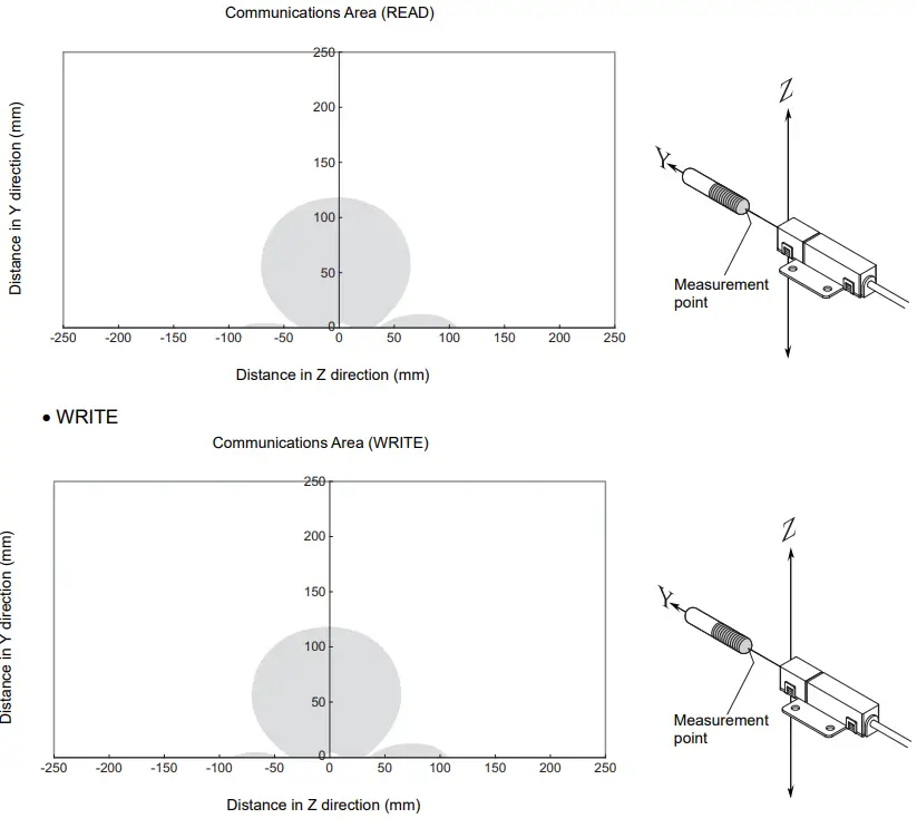
- Parallel Mounting (RI-TRP-WR2B)
- READ
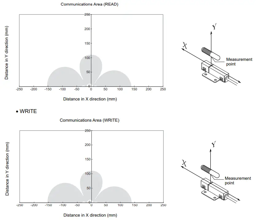
- Parallel Mounting (RI-TRP-WR2B)
- READ
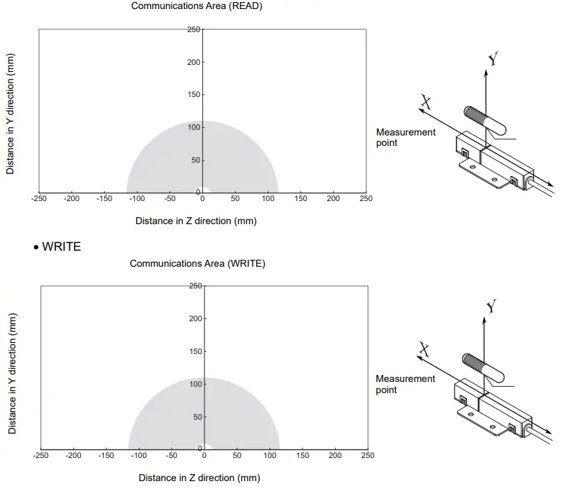
- Vertical Mounting (RI-TRP-WR2B)
- READ
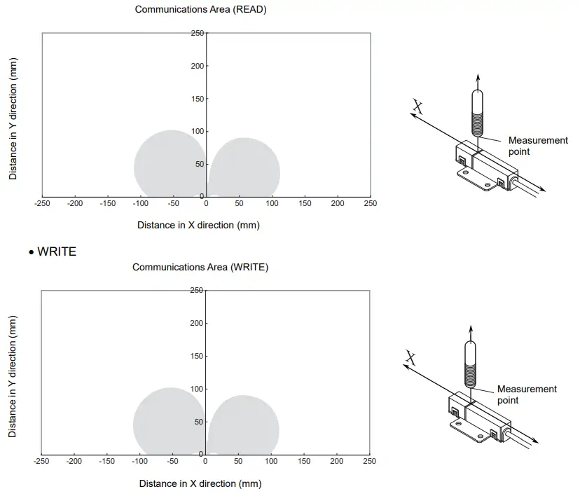
- Vertical Mounting (RI-TRP-WR2B)
- READ
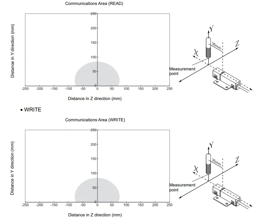
- V640-HAM11-L-ETN-V2
- Coaxial Mounting (RI-TRP-DR2B-30)
- READ
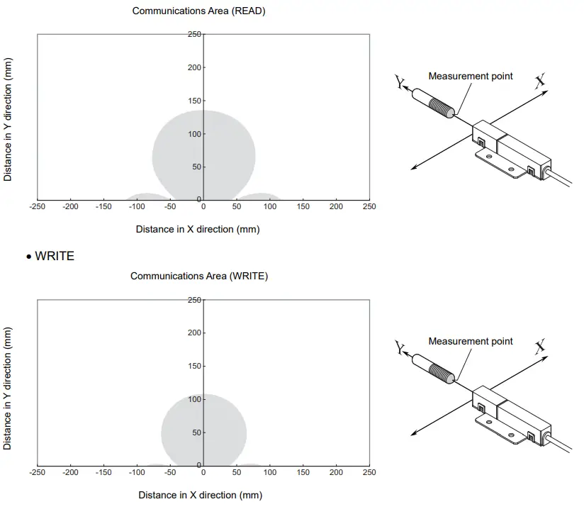
- Coaxial Mounting (RI-TRP-DR2B-30)
- READ
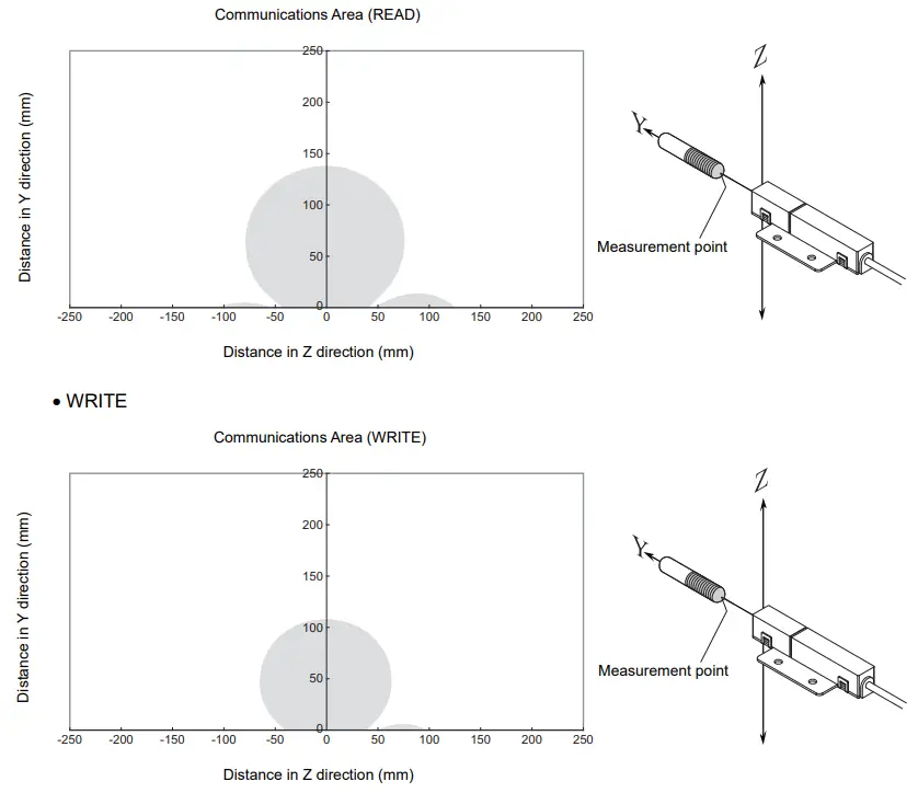
- Parallel Mounting (RI-TRP-DR2B-30)
- READ
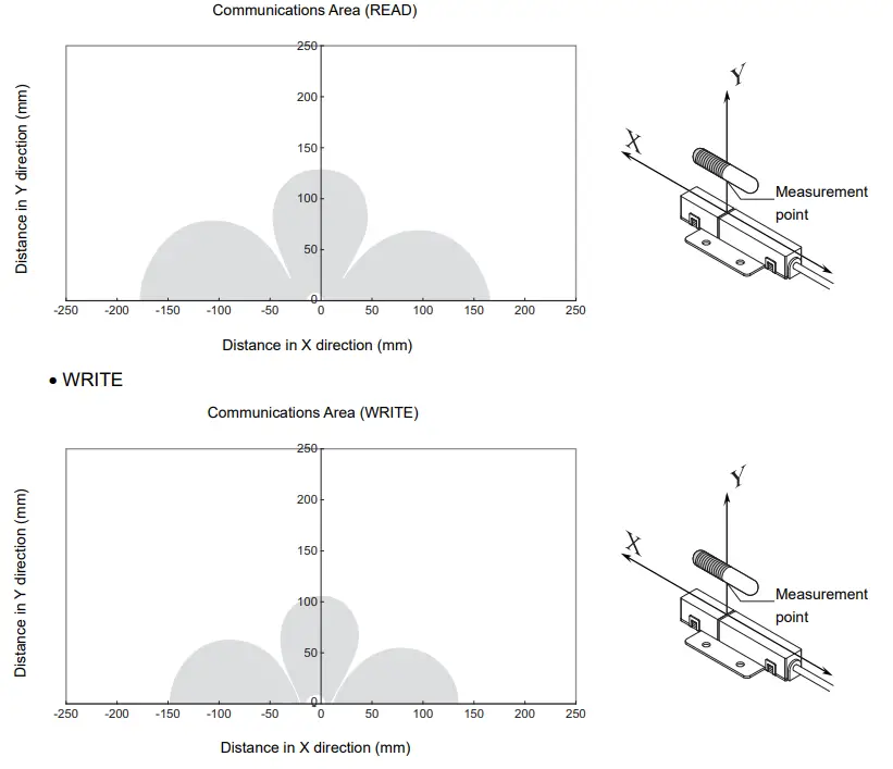
- Parallel Mounting (RI-TRP-DR2B-30)
- READ
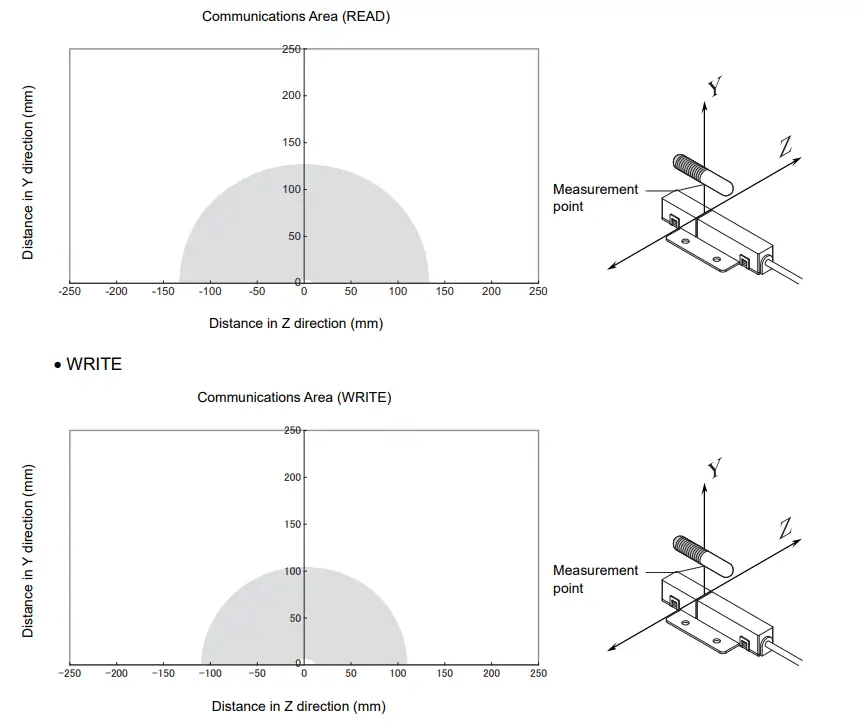
- Vertical Mounting (RI-TRP-DR2B-30)
- READ
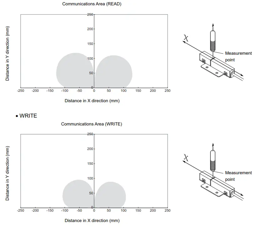
- Vertical Mounting (RI-TRP-DR2B-30)
- READ
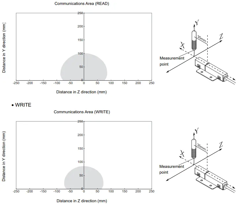
- Coaxial Mounting (RI-TRP-WR2B)
- READ
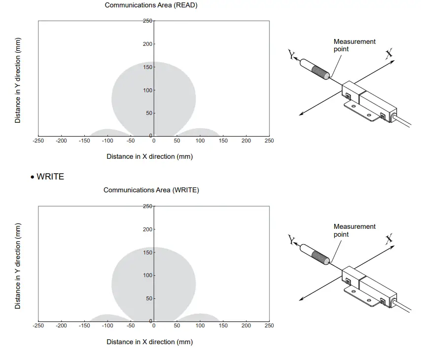
- Coaxial Mounting (RI-TRP-WR2B)
- READ
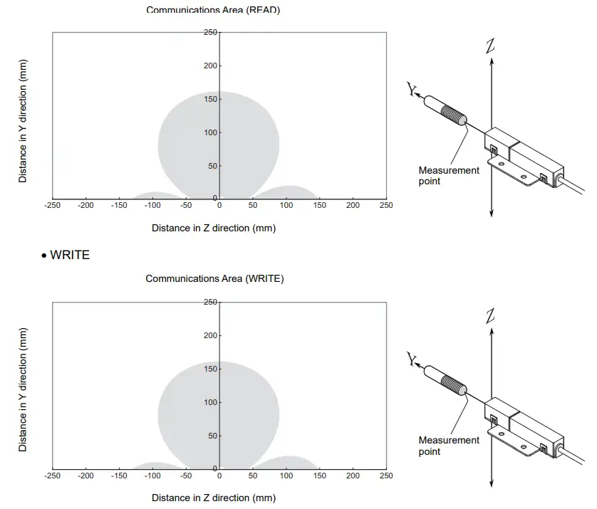
- Parallel Mounting (RI-TRP-WR2B)
- READ
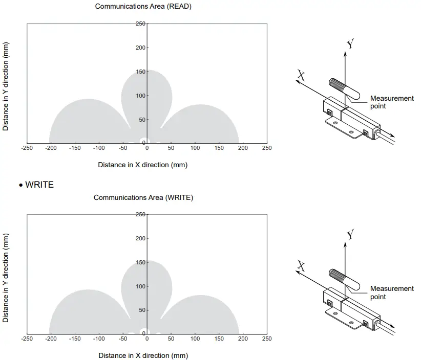
- Parallel Mounting (RI-TRP-WR2B)
- READ
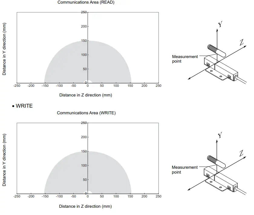
- Vertical Mounting (RI-TRP-WR2B)
- READ
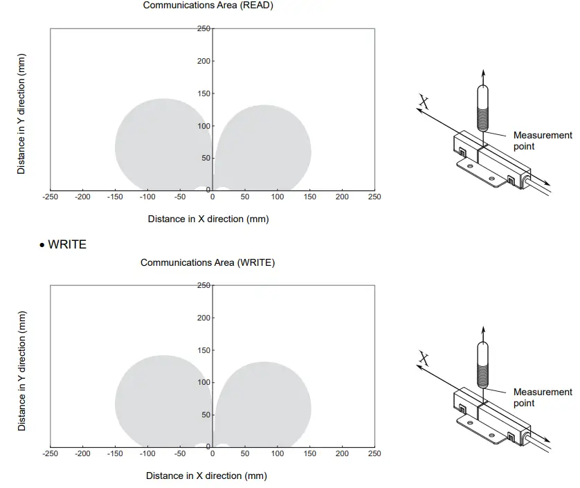
- Vertical Mounting (RI-TRP-WR2B)
- READ
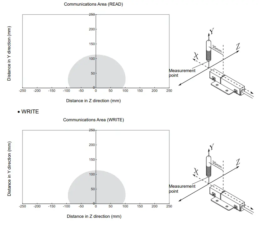
![]() Mutual Interference Distances (Reference Only)
Mutual Interference Distances (Reference Only)
- When amplifier units are connected using multidrop connections and multiple CIDRW Heads are used
The CIDRW Heads will not process commands simultaneously. In this case, install the CIDRW Heads at least 0.1 m apart from each other. - When the CIDRW Systems are installed close to each other
Distance between Antennas and Changes in Communications Distances (Reference Only) - V640-HS61
| Distance between Antennas | Change in communications distance |
| 1,000 mm | 100% |
| 900 mm | 100% |
| 800 mm | 100% |
| 700 mm | 99% |
| 600 mm | 90% |
| 500 mm | 74% |
| 400 mm | 55% |
| 300 mm | 40% |
| 200 mm | 15% |
- V640-HS62
| Distance between Antennas | Change in communications distance |
| 2,000 mm | 99% |
| 1,600 mm | 99% |
| 1,400 mm | 95% |
| 1,200 mm | 84% |
| 1,000 mm | 68% |
| 800 mm | 53% |
| 600 mm | 34% |
| 400 mm | 15% |
| 200 mm | 0% |
If CIDRW Heads in separate CIDRW systems process commands simultaneously, mutual interference between the Heads can result in malfunctions. If this is a problem, install the CIDRW Heads separated at least by the distances shown in the following illustrations.
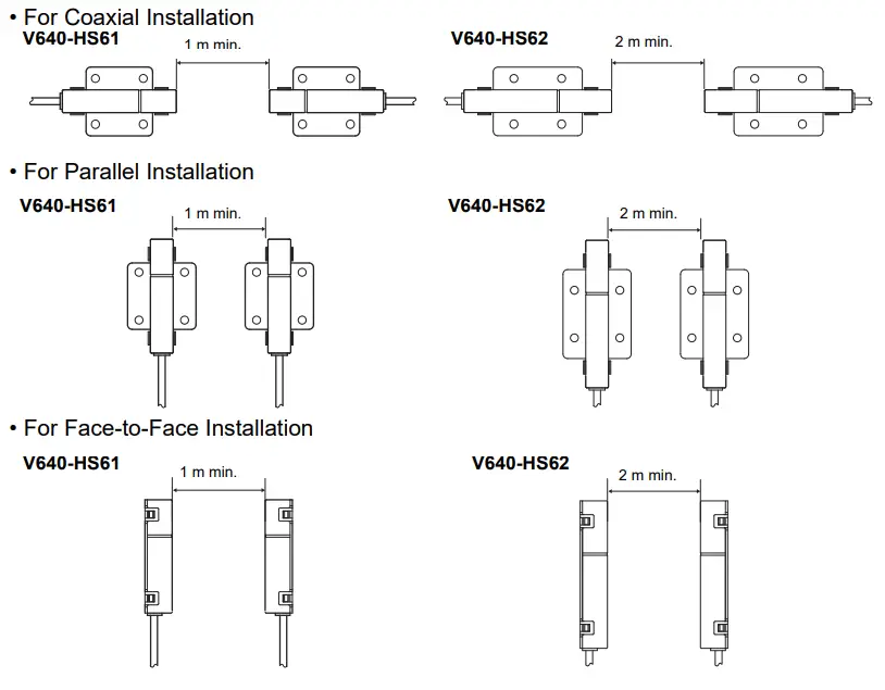
![]() Influence of Background Metals (Reference Only)
Influence of Background Metals (Reference Only)
The CIDRW Head can also communicate from an opening in a ceiling panel (metal body).
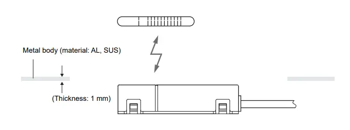
However, ensure the distances indicated below between the CIDRW Head and the metal body. If you do not ensure these distances the communications distance will be substantially shortened.
- V640-HS61
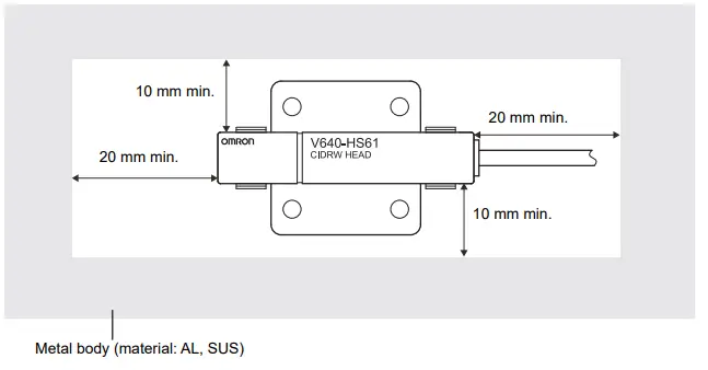
- V640-HS62
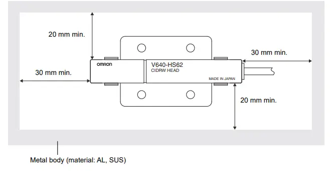
![]() Communications Time
Communications Time
Regardless of whether SECS is used or not, take the time required for processing between the host device and Amplifier Units into account when designing the system.
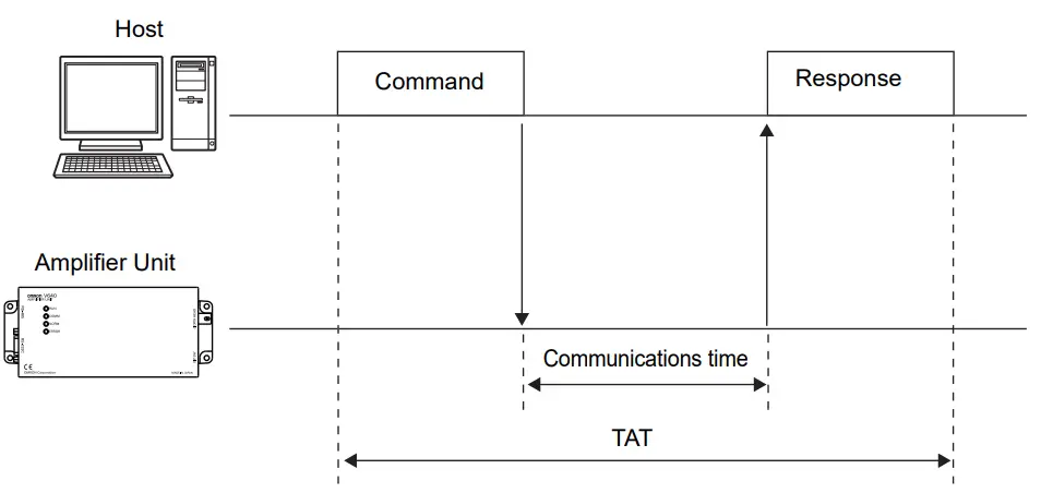
| Time | Description |
| Communications time | This is the time required for communications between an ID Tag and the CIDRW Head. |
| TAT | This is the time required for processing at the Amplifier Unit, seen from the host device. |
Communications time calculation formula (unit: ms)

TAT calculation formula (units: ms)
TAT = command and response transmission time + communications time
*The command and response transmission time differs depending on the network environment.
For example: Command and response transemission time is about from 10 to 40msec, when connect between PC and the Amplifier Unit directly by the lan cable(100M).
The graph for communications time for communications between the ID Tag and CIDRW Head, and
TAT (when the baud rate is 9600 bps), is shown below.
The communications time and TAT, however, may increase substantially according to the conditions of use.
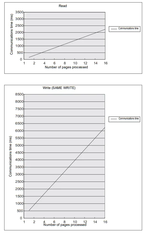
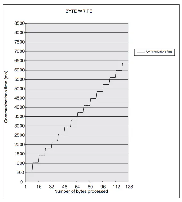
![]() Please confirm beforehand, there is a difference in comparision with V640-HAM11-ETN and V640HAM11-L-ETN in communication time.
Please confirm beforehand, there is a difference in comparision with V640-HAM11-ETN and V640HAM11-L-ETN in communication time.
![]() Communications Distance Characteristics vs. Ambient Noise
Communications Distance Characteristics vs. Ambient Noise
The graph below compares the results of measurement using the noise measurement function with communications distances.
At installation implement measures in regard to metal in the vicinity of the CIDRW Head, power supply noise, and atmospheric noise, to ensure that the noise level does not exceed 10.
NOISE MEASUREMENT command (applies only when SECS is not used)
- V640-HAM11-ETN-V2
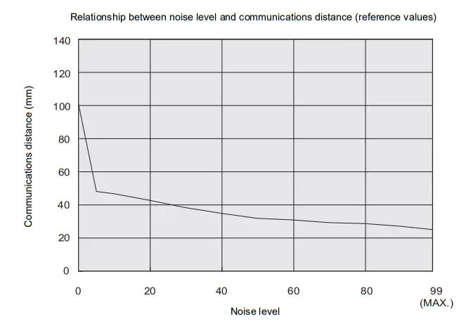
- V640-HAM11-L-ETN-V2
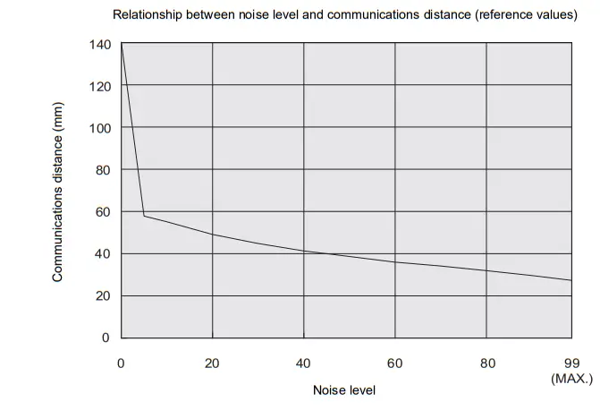
ID Tag Memory Maps
The memory maps of the RI-TRP-DR2B(-30) and RI-TRP-WR2B(-30) ID Tags are given below
- RI-TRP-DR2B(-30)
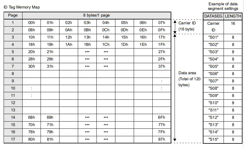
- The carrier ID memory area starts from page 1 (fixed).
- 00h to 87h in the table are addresses.
- The RI-TRP-WR2B(-30) has a memory capacity of 136 bytes.
- RI-TRP-WR2B(-30)
ID Tag Memory Map
| Page | 8 bytes/1 page | |||||||
| 1 | 00h | 01h | 02h | 03h | 04h | 05h | 06h | 07h |
Carrier ID (8 byte)
Example of data segment settings
- The RI-TRP-WR2B(-30) has a memory capacity of 8 bytes.
Regular Inspection
In order to maintain optimum performance of the functions of the CIDRW system, daily and periodic inspections are necessary.
| Inspection item | Detail | Criteria | Tools required | |
| Supply voltage fluctuation | Check that the supply voltage fluctuation at the power supply terminal block is within the permissible range. | To be within supply voltage rating. | Multimeter | |
| Check that there are no frequent instan- taneous power failures or radical voltage drops. | To be within permissible voltage fluctua- tion range. | Power supply analyzer | ||
| Environment | Ambient tem- perature | Check that the ambient temperature and humidity are within specified range. | To be within the specified range. | Maximum and minimum ther- mometer Hygrometer |
| Ambient humidity | ||||
| Vibration and shock | Check that no vibration or shock is trans- mitted from any machines. | |||
| Dust | Check that the system is free of dust accumulation. | To be none. | ||
| Corrosive gas | Check that no metal part of the system is discolored or corroded. | |||
| I/O power supply | Voltage fluctu- ation | Check on the I/O terminal block that the voltage fluctuation and ripple are within the permissible ranges. | To be within the specified range. | Multimeter Oscilloscope |
| Ripple | ||||
| Mounting condition | Check that each device is securely mounted. | There must be no loose screws. | — | |
| Check that each connector is securely connected. | Each connector must be locked or securely tightened with screws. | |||
| Check that no wire is broken or nearly broken. | There must be no wire that is broken or nearly broken. | |||
| Check if grounding to 100 L or less has been done. | To be grounded to 100 L or less. | |||
ASCII Code Table
| Leftmost bits
Right- most bits |
b8 to b5 |
0000 |
1001 |
0010 |
0011 |
0100 |
0101 |
0110 |
0111 |
1000 |
1101 |
1010 |
1011 |
1100 |
1101 |
1110 |
1111 |
| b4 to b1 | Row
Line | 0 | 1 | 2 | 3 | 4 | 5 | 6 | 7 | 8 | 9 | 10 | 11 | 12 | 13 | 14 | 15 |
| 0000 | 0 | NUL | TC7(DLE) | (SP) | 0 | @ | P | ` | p |
Undefined |
Undefined |
Undefined | |||||
| 0001 | 1 | TC1(SOH) | DC1 | ! | 1 | A | Q | a | q | ||||||||
| 0010 | 2 | TC2(STX) | DC2 | “ | 2 | B | R | b | r | ||||||||
| 0011 | 3 | TC3(ETX) | DC3 | # | 3 | C | S | c | s | ||||||||
| 0100 | 4 | TC4(EOT) | DC4 | $ | 4 | D | T | d | t | ||||||||
| 0101 | 5 | TC5(NEQ) | TC8(NAK) | % | 5 | E | U | e | u | ||||||||
| 0110 | 6 | TC6(ACK) | TC9(SYN) | & | 6 | F | V | f | v | ||||||||
| 0111 | 7 | BEL | TC10(ETB) | ‘ | 7 | G | W | g | w | ||||||||
| 1000 | 5 | FE0(BS) | CAN | ( | 8 | H | X | h | x | ||||||||
| 1001 | 9 | FE1(HT) | EM | ) | 9 | I | Y | i | y | ||||||||
| 1010 | 10 | FE2(LF) | SUB | * | : | J | Z | j | z | ||||||||
| 1011 | 11 | FE3(VT) | ESC | + | ; | K | [ | k | { | ||||||||
| 1100 | 12 | FE4(FF) | IS4(FS) | , | < | L | \ | l | | | ||||||||
| 1101 | 13 | FE5(CR) | IS3(GS) | – | = | M | ] | m | } | ||||||||
| 1110 | 14 | S0 | IS2(RS) | . | > | N | ^ | n | ÅP | ||||||||
| 1111 | 15 | S1 | IS1(US) | / | ? | O | _ | o | DEL | ||||||||
Protective Construction
IP- ![]() is governed by the test methods described below. Check in advance the seal characteristics under the actual environment and conditions of use.
is governed by the test methods described below. Check in advance the seal characteristics under the actual environment and conditions of use.
IP is the abbreviation of International Protection.
- IEC (International Electrotechnical Commission) Standard (IEC60529: 2001)
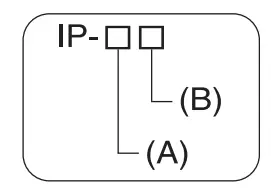
(A) First numeral in code: Class of protection against entry of solid foreign material
| Class | Degree of protection | |
| 0 | No protection | |
| 1 | 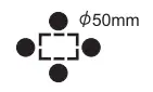 | Protected against access by solid objects with a diameter of 50 mm or greater (e.g., human hands). |
| 2 |  | Protected against access by solid objects with a diameter of 12.5 mm or greater (e.g., fingers). |
| 3 | 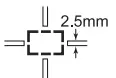 | Protected against access by wires and solid bodies with a diameter of 2.5 mm or greater. |
| 4 | 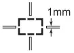 | Protected against access by wires and solid bodies with a diameter of 1 mm or greater. |
| 5 |  | Entry of volumes of dust that would cause difficulties in normal operation of devices or compromise safety is prevented. |
| 6 |  | Entry of dust is prevented. |
(B) Second numeral of code: Class of protection against the entry of water
| Class | Degree of protection | Outline of test methods (tests using water) | |
| 0 | No special protection | No protection against the entry of water. | No test |
| 1 | Protection against droplets of water
| The product suffers no ill effects from droplets of water falling vertically onto it. | Water droplets are sprayed onto the product from directly above for 10 minutes by water droplet exposure test apparatus.
|
| 2 | Protection against droplets of water | The product suffers no ill effects from droplets of water directed at it at an angle of up to 15° to vertical. | The water droplet expo- sure test apparatus is set to 15° from vertical and water droplets sprayed onto the product for 10 minutes (total of 25 min- utes in each direction).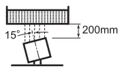 |

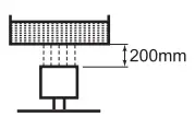
| Class | Degree of protection | Outline of test methods (tests using water) | |
| 3 | Protection against spraying water | The product suffers no ill effects from a water spray directed at it at up to 60° from vertical. | Using the test apparatus shown in the figure to the right, water is sprayed from both directions, onto both sides of the product, at angles up to 60° from vertical for 10 minutes.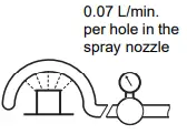 |
| 4 | Protection against splashing water  | The product suffers no ill effects from water splashed on it from all directions. | Using the test apparatus shown in the figure to the right, water is splashed onto the product from all directions for 10 minutes.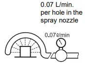 |
| 5 | Protection against water jets
| The product suffers no ill effects from a water jet aimed directly at it from all directions. | Using the test apparatus shown in the figure to the right, a water jet is directed at the product from all directions for 1 minute per square meter of outer casing, with a minimum total exposure of 3 minutes. 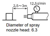 |
| 6 | Protection against powerful jets of water | Water does not enter the product when a powerful jet of water is directed at it from all directions. | Using the test apparatus shown in the figure to the right, a water jet is directed at the product from all directions for 1 minute per square meter of outer casing, with a minimum total exposure of 3 minutes.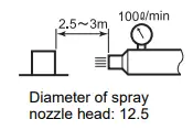 |
| 7 | Protection against immer- sion in water | No entry of water on immersion in water at the stipulated pressure for the stipulated time. | Immerse in water for 30 minutes at a depth of 1 meter (when the height of the apparatus is less than 850 mm).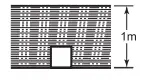 |
| 8 (See note. | Protection against immersion in water | The product can be used while continually immersed in water. | Depends on arrange- ments made between the manufacturer and the user of the product. |

Note: OMRON Test Method
Usage condition: 10 m or less under water in natural conditions
- No water ingress after 1 hour under water at 2 atmospheres of pressure.
- Sensing distance and insulation resistance specifications must be met after 100 repetitions of half hour in 5°C water and half hour in 85°C water.
About IPX9K
IPX9K is a protection standard regarding high temperature and high-pressure water which is defined by the German standard (DIN 40050 PART9).
Water is sprayed on 80 °C hot water with the water pressure of 80 to 100BAR from a nozzle to the test piece.
Amount of water is 14 to 16 liters/minute.
The distance between the test piece and a nozzle is 10 to 15 cm, and the directions of waterdrainage are 0 degrees, 30 degrees, 60 degrees, and 90 degrees horizontally. They are evaluated with the test piece is rotating on a horizontal plane by 30 seconds in each direction.
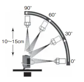
- Oil Resistance (OMRON in-house standard)
| Protection | |
| Oil-resistant | No adverse affect from oil drops or oil spray approaching from any direction. |
| Oil-proof | Protects against penetration of oil drops or oil spray approaching from any direction. |
Note. Oil resistance has been tested using a specific oil as defined in the OMRON test method. (JIS C 0920:2003, Appendix 1)
Revision History
A manual revision code appears as a suffix to the catalog number on the front cover of the manual.
The following table outlines the changes made to the manual during each revision. Page numbers refer to the previous version.
| Revision code | Date | Revised content |
| 01 | June 2015 | Original production |
| 02 | November 2015 | Changed the Maps of Communications Areas. |
| 03 | January 2017 | Changed the description of the operating environment of the WEB browser. |
| 04 | June 2019 | Changed the description of Java version. |
| 05 | December 2019 | Added the following information. ・Set the IP address on the computer ・Setting the Communications Conditions for Amplifier Units ・Cannot Display the Web Browser Operation Window |
| 06 | October 2022 | ・Added safety precautions regarding security. ・Added description about Windows application “V640 Utility Tool”. |
OMRON Corporation Industrial Automation Company
Kyoto, JAPAN
Contact : www.ia.omron.com
Regional Headquarters
OMRON EUROPE B.V.
Wegalaan 67-69, 2132 JD Hoofddorp
The Netherlands
Tel: (31) 2356-81-300 Fax: (31) 2356-81-388
OMRON ASIA PACIFIC PTE. LTD.
438B Alexandra Road, #08-01/02 Alexandra
Technopark, Singapore 119968
Tel: (65) 6835-3011 Fax: (65) 6835-2711
OMRON ELECTRONICS LLC
2895 Greenspoint Parkway, Suite 200
Hoffman Estates, IL 60169 U.S.A.
Tel: (1) 847-843-7900 Fax: (1) 847-843-7787
OMRON (CHINA) CO., LTD.
Room 2211, Bank of China Tower,
200 Yin Cheng Zhong Road,
PuDong New Area, Shanghai, 200120, China
Tel: (86) 21-5037-2222 Fax: (86) 21-5037-2200
Authorized Distributor:
©OMRON Corporation 2015-2022 All Rights Reserved.
In the interest of product improvement,
specifications are subject to change without notice.
Cat. No. Z361-E1-06 1022


