Hopeland HL7206C12 24 RFID Reader
1. Technical Specification
Feature
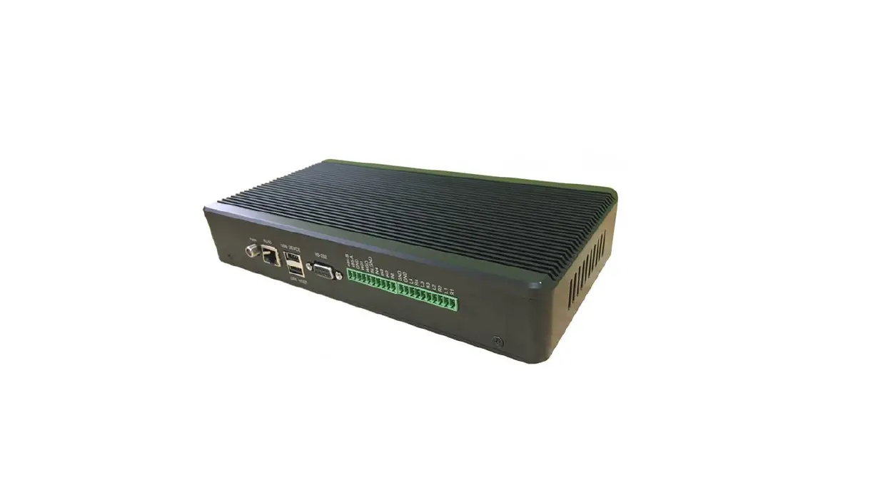
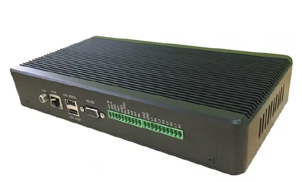
HL7206C12/24 is a high performance 12/24 antenna port fixed UHF RFID reader; support ISO18000-6C/6B protocols. The work frequency includes China standard dual frequency 920MHz ~ 925MHz and 840MHz~845MHz, FCC 902MHz ~ 928MHz and ETSI 865MHz ~ 868MHz.
Output power from 0 ~ 33dBm optional, with long identification distance, fast reading speed, high accurate rate, strong anti-interference ability, good protection performance and easy installation.
Technical
Main function
- Air interface protocol: support ISO18000-6C/6B standard
- Built-in LINUX operating system
- Multiple communication port (Ethernet, RS232, RS485, USB), Wi-Fi extensible
- Support tag data filtering
- Support RSSI: the intensity of the perceived signal
- Adjustable RF output power
- Optional working mode: constant frequency / frequency hopping
- Support antenna detection function
- Support online and remote upgrade
- I/O interface: 4 port optocoupler input, 4 port relay output and Wiegand output
Technical parameter
- Working frequency: GB 920MHz~925MHz, GB 840MHz~845MHz, FCC 902MHz~928MHz, ETSI 865MHz~868MHz
- Output power (port): 33dBm ± 1dB (MAX)
- Power adjustment: 1 dB step-by-step
- Reading distance: 0 ~8meters (depending on tags, antennas and environment)
- Channel bandwidth: <200 KHz
- RS232 serial communication rate: 115200bps (default), 19200 bps, 9600bps
- RS485 interface communication rate: 115200bps (default), 19200 bps, 9600bps
- Support: Wiegand 26, 34, 66
- Power supply: 10V ~ 30V(power capacity is not less than 60W)
- Power adapter: AC input 100V ~ 240V, 50Hz ~ 60HzDC output: 24V/2.5A
1.2.3 Operational environment
- Working environment: -20℃~+70℃
- Relative Humidity: 5%RH~90%RH(+25℃)
FCC warning:
This device complies with Part 15 of the FCC Rules. Operation is subject to the following three conditions:
This device may not cause harmful interference, and
This device must accept any interference received, including interference that may cause undesired operation.
The distance between user and products should be no less than 20cm
NOTE: This equipment has been tested and found to comply with the limits for a Class B digital device, pursuant to Part 15 of the FCC Rules. These limits are designed to provide reasonable protection against harmful interference in a residential installation. This equipment generates, uses and can radiate radio frequency energy and, if not installed and used in accordance with the instructions, may cause harmful interference to radio communications. However, there is no guarantee that interference will not occur in a particular installation. If this equipment does cause harmful interference to radio or television reception, which can be determined by turning the equipment off and on, the user is encouraged to try to correct the interference by one or more of the following measures:
- Reorient or relocate the receiving antenna.
- Increase the separation between the equipment and receiver.
- Connect the equipment into an outlet on a circuit different from that to which the receiver is connected.
- Consult the dealer or an experienced radio/TV technician for help.
Note: The manufacturer is not responsible for any radio or TV interference caused by unauthorized modifications to this equipment. such modifications could void the user ’s authority to operate this equipment
Changes or modifications not expressly approved by the party responsible for compliance could void the user’s authority to operate the equipment.
Sketch map
Physical construction 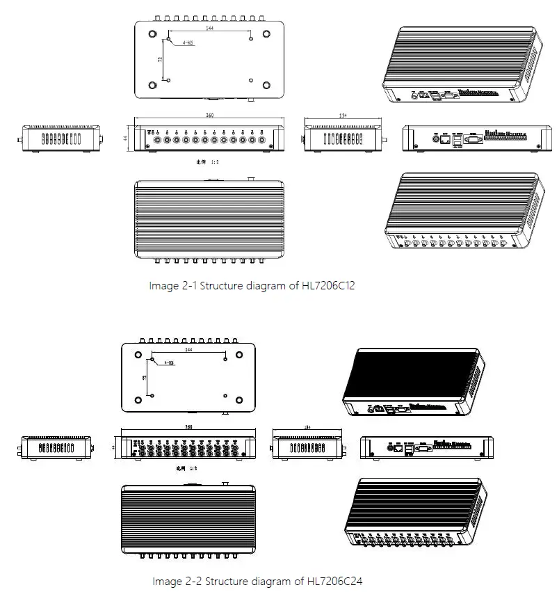
Weight
1.41kg
Illustration of LED display
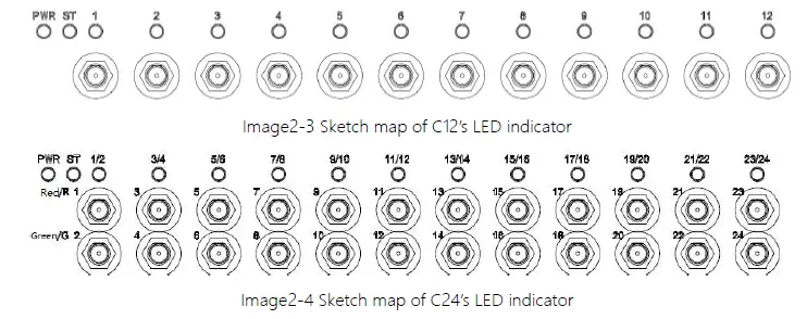
HL7206C12 LED indicator panel describe as below Form 2-1:
Form 2-1 HL7206C12 LED indicator description
| LED Mark NO. | Mark NO. | Status description |
| POWER | Power indicator | Keep bright indicates power supply working normally |
| ST | Status indicator | Keep bright indicates tag be read |
| ANT1 | Antenna 1 indicator | Indicates antenna 1 is working |
| ANT2 | Antenna 2 indicator | Indicates antenna 2 is working |
| ANT3 | Antenna 3 indicator | Indicates antenna 3 is working |
| ANT4 | Antenna 4 indicator | Indicates antenna 4 is working |
| ANT5 | Antenna 5 indicator | Indicates antenna 5 is working |
| ANT6 | Antenna 6 indicator | Indicates antenna 6 is working |
| ANT7 | Antenna 7 indicator | Indicates antenna 7 is working |
| ANT8 | Antenna 8 indicator | Indicates antenna 8 is working |
| ANT9 | Antenna 9 indicator | Indicates antenna 9 is working |
| ANT10 | Antenna 10 indicator | Indicates antenna 10 is working |
| ANT11 | Antenna 11 indicator | Indicates antenna 11 is working |
| ANT12 | Antenna 12 indicator | Indicates antenna 12 is working |
| LED Mark NO. | Mark NO. | Status description |
| POWER | Power indicator | Keep bright indicates power supply working normally |
| ST | Status indicator | Keep bright indicates tag be read |
| ANT1/2 | Antenna 1/2 indicator | bi-colour light, red Indicates antenna 1 is working, green indicates antenna 2 is working |
| ANT3/4 | Antenna 3/4 indicator | bi-colour light, red Indicates antenna 3 is working, green indicates antenna4 is working |
| ANT5/6 | Antenna 5/6 indicator | bi-colour light, red Indicates antenna 5 is working, green indicates antenna 6 is working |
| ANT7/8 | Antenna 7/8 indicator | bi-colour light, red Indicates antenna 7 is working, green indicates antenna 8 is working |
| ANT9/10 | Antenna 9/10 indicator | bi-colour light, red Indicates antenna 9 is working, green indicates antenna 10 is working |
| ANT11/12 | Antenna 11/12 indicator | bi-colour light, red Indicates antenna 11 is working, green indicates antenna 12 is working |
| ANT13/14 | Antenna 13/14 indicator | bi-colour light, red Indicates antenna 13 is working, green indicates antenna 14 is working |
| ANT15/16 | Antenna 15/16 indicator | bi-colour light, red Indicates antenna 15 is working, green indicates antenna 16 is working |
| ANT17/18 | Antenna 17/18 indicator | bi-colour light, red Indicates antenna 17 is working, green indicates antenna 18 is working |
| ANT19/20 | Antenna 19/20 indicator | bi-colour light, red Indicates antenna 19 is working, green indicates antenna 20 is working |
| ANT21/22 | Antenna 21/22 indicator | bi-colour light, red Indicates antenna 21 is working, green indicates antenna 22 is working |
| ANT23/24 | Antenna 23/24 indicator | bi-colour light, red Indicates antenna 23 is working, green indicates antenna 24 is working |
Interfaces
Power supply, communication and I/O interface
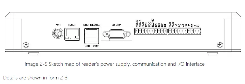
Form 2-3 Reader’s power supply, communication and I/O interface
| Interface ID | Interface Name | Detail description |
| POWER | Power supply | DC, 10~30V, power capacity no less than 60W. |
| RJ45 | Ethernet interface | 10/100M Ethernet interface, the reader communication interface. |
| USB DEVICE | USB device port | Connecting PC or other upper computer, communication interface. |
| USB HOST | USB host port | For external U disk, wireless LAN card and other expansion devices. |
| RS-232 | RS-232 serial port | Serial port, the reader control and communication interface. |
| Other | I/O interface | See detailed definition 2.4.2. |
I/O Interface definition
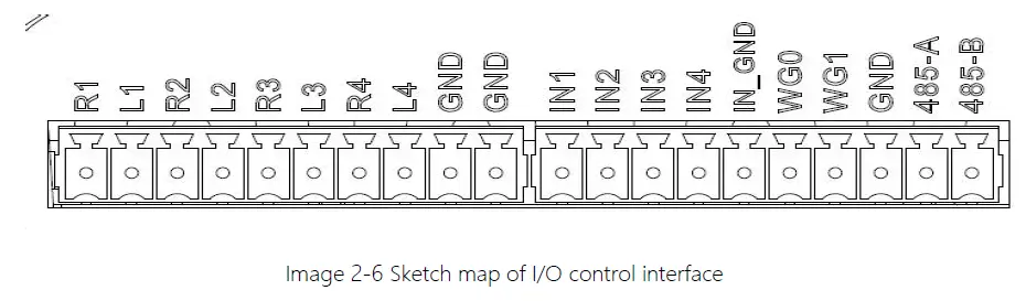
| Pin ID | Pin Description |
| R1 | Relay 1# output; DC_MAX: 30V, 2A; AC_MAX: 125V, 0.3A; logic ‘0’ indicates open circuit, logic ‘1’ indicates closed, default is open circuit. |
| L1 | Relay 1# output; DC_MAX: 30V, 2A; AC_MAX: 125V, 0.3A; logic ‘0’ indicates open circuit, logic ‘1’ indicates closed, default is open circuit. |
| R2 | Relay 2# output; DC_MAX: 30V, 2A; AC_MAX: 125V, 0.3A; logic ‘0’ indicates open circuit, logic ‘1’ indicates closed, default is open circuit. |
| L2 | Relay 2# output; DC_MAX: 30V, 2A; AC_MAX: 125V, 0.3A; logic ‘0’ indicates open circuit, logic ‘1’ indicates closed, default is open circuit. |
| R3 | Relay 3# output; DC_MAX: 30V, 2A; AC_MAX: 125V, 0.3A; logic ‘0’ indicates open circuit, logic ‘1’ indicates closed, default is open circuit. |
| L3 | Relay 3# output; DC_MAX: 30V, 2A; AC_MAX: 125V, 0.3A; logic ‘0’ indicates open circuit, logic ‘1’ indicates closed, default is open circuit. |
| R4 | Relay 4# output; DC_MAX: 30V, 2A; AC_MAX: 125V, 0.3A; logic ‘0’ indicates open circuit, logic ‘1’ indicates closed, default is open circuit. |
| L4 | Relay 4# output; DC_MAX: 30V, 2A; AC_MAX: 125V, 0.3A; logic ‘0’ indicates open circuit, logic ‘1’ indicates closed, default is open circuit. |
| GND | Ground |
| GND | Ground |
| IN1 | Optocoupler 1# input, DC 0~24V, higher than 1V is high level, lower than 1V is low level |
| IN2 | Optocoupler 2# input, DC 0~24V, higher than 1V is high level, lower than 1V is low level |
| IN3 | Optocoupler 3# input, DC 0~24V, higher than 1V is high level, lower than 1V is low level |
| IN4 | Optocoupler 4# input, DC 0~24V, higher than 1V is high level, lower than 1V is low level |
| IN_GND | Optocoupler input ground, reader optocoupler external input signal ground |
| WG0 | Wiegand data 0 signal, the default state is high level |
| WG1 | Wiegand data 1 signal, the default state is high level |
| GND | Ground |
| 485-A | RS485 A signal |
| 485-B | RS485 B signal |
Coaxial RF Feeder Cable (optional)
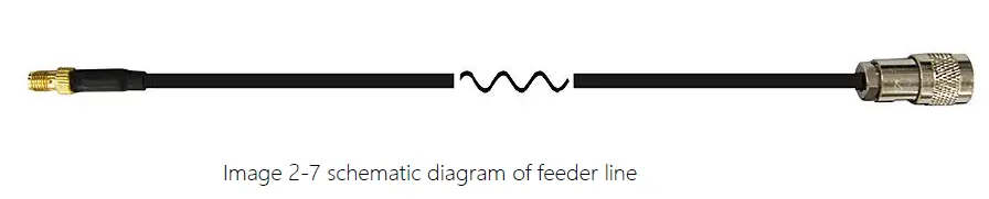 RF cable TNC(Reverse polarity, internal thread, inner pin) connector connects with reader antenna TNC connector, RF cable SMA connector connect with external circular polarization antenna’s SMA connector, cable maximum length is 5m, impedance 50Ω, insertion loss is less than 2dB, high-performance cable can also be selected, and the length can be increased appropriately, insertion loss is less than 2dB.
Note: Poor contact of cable connector or an ultra-long RF cable can cause excessive attenuation of the transmitted signal and received echo signal, resulting in deterioration of read/write performance.
Network connection diagram
Network interface used for long-distance high-speed connection (less than 80 m), can be connected with the switcher or router through the network cable, or directly connected with the PC network interface, as shown in figure 2-7: 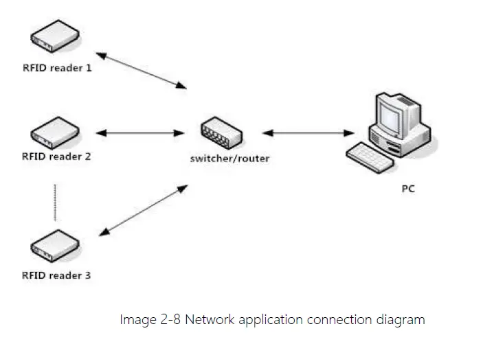
Installation
Notes
To ensure the normal and stable operation of the device and your personal property and safety, please carefully read the following notes before install HL7206C reader and writer:
1. Firstly, check whether the power socket is connected to the ground, and to see whether the local power supply voltage is in accordance with the applicable voltage range of the reader;
2. Check the device and the external connection if is closely connected;
3. Pay attention to the type selection and the length limit of the network cable and the serial cable:
Network cable connects directly, no longer than 80 meters
Serial cable connects directly, no longer than 10 meters
4. When installing several readers, the antenna position and the antenna spacing should be appropriate to avoid interference with each other.
Installation conditions
Before installing the reader, please check carefully whether the product is in good condition and the accessories are complete. If there is any part missing or damage, please contact the supplier in time.
Device connection
Power on
Insert the power cord into the AC power supply socket and plug another end into the power connector of the device and tighten. Turn on and wait about 20 seconds, the system initialization process is completed and is standby state.
Antenna connection
The device built with four TNC coaxial cable connector for connecting an external antenna, select low consumption RF cable, connectors should be tightened (Ensure to be waterproof when install outdoors);
Adjust the reader antenna angle or tilt to the best position through the actual test according to the specific application
PC connection
The device provides special adapter cable, including interface of network, serial and power,
RS232 interface is for short distance communication (less than 10m), through the DB9 connector and the PC serial port connection to realize the communication of PC and the device,
RJ45 network port used for long distance communication (less than 80m), connect PC with extend network cable.
Device installation
The reading and writing range of the reader depends on the on-site application, the tilt angle of the antenna is adjusted to achieve the best reading and writing performance.
Acceptance
Mainly from two aspects of acceptance criteria: structure and performance.
Acceptance of structure
Check below details:
- Whether reader is fixed firmly, without loose
- Whether the cable connected firmly
- Whether the screws are tighten
Performance acceptance
- Whether the reader is working properly
- Whether the read and write range is reasonable
Common failures
Daily maintenance
The routine maintenance of HL7206C12/24 usage:
- To check whether the tightening of RF connector
- To check if the screw fixed reader and antenna is loose
- To check whether the RF cable connector is disconnected from the shielding layer
- To check if the reader power cable connection is reliable
Common failure analysis and solution
- Power supply system failures:
- Check whether the power adapter is normal, and the AC supply voltage is between 100V ~ 240V. The panel indicator light failed when power on:
- Check whether the communication is normal; please contact customer service if it’s not normal. The serial port unable to connect:
- Check if the serial cable is not connected or connected unstable.
- Check if the serial port connect baud rate of the reader is correct
- Check if the selected COM port is right.
- The network port cannot connect:
- The default IP address and port of HL7206C12/24 is 192.168.1.116:9090 ensure the IP address of the PC and reader in the same network segment, such as “192.168.1.XXX” then you can connect to the reader, if you forget the IP address of the device, you can reset the reader’s IP address through the serial port.
The reader can’t read the tag
- Check if the setting of antenna number is correct
- Check if the label is damaged
- Check if the label is placed in the reader’s valid reading and writing range.
- Check if the electromagnetic interference between the reader and the other device. For the problem users cannot solve, please contact customer service.
Package
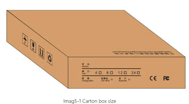 Carton box size: 315X292X82mm
Accessories
In order to facilitate the storage and transportation in near future, the packing box and the packing material should be kept properly after unpack.
Besides of the device in the box, accessories equipped with the reader are also included in, please check the product packing list to confirm whether the product and accessories are complete, if any discrepancies or damage, please contact with the after-sale service in time.
The specific list of accessories as shown in table 5-1
Table 5-1 Package list
| NO. | Name | Material Code | Qty | Unit | Remark |
| 1 | HL7206C12/24 12/24-port fixed reader | —————— | 1 | set | Included |
| 2 | Power adapter 24V/2.5A | 20109000000324 | 1 | pcs | Included |
| 3 | AC power cord | 20350000000195 | 1 | unit | Included |
| 4 | Network cable | 20350000000188 | 1 | unit | Included |
| 5 | RS232 black cable | 20351000000478 | 1 | pcs | Included |
| 6 | USB cable | 20351000000036 | 1 | pcs | Included |
| 7 | Warranty card | 20420000001651 | 1 | pcs | Included |
| 8 | Certificate of approval | 20420000001650 | 1 | pcs | Included |
5.3 Storage environment
HL7206C12/24 fixed reader should be stored in below conditions:
- Environment temperature:-40℃~+85℃
- Relative humidity:5% RH~90%RH
After-sale service
Letter to Customers
Since our aim is to continuously improve our products for better user experience, we may modify the product characteristics, composition and design of circuits without given notifications. Thus the real product may be not in accordance with this manual. Generally, we will provide timely amendments to this manual. If it’s not provided timely, please consult our service department. Shenzhen Hopeland Technologies Co., Ltd.
Email: [email protected]
Tell: +86 755 33218493
Website: http://www.hopelandrfid.com
Address: F5# Bldg, TCL International E-city, No.1001, Zhongshan Park Road, Nanshan
district,Shenzhen,P.R.China
Guarantee card of Shenzhen Hopeland Technology Co.,Ltd
| Product Name | Model No. | |||
| Product Code | Level | |||
| Description of troubles | ||||
| User’s name | Postcode | |||
| Contact person | Contact no. | |||
Address of factory: Block 3 of CLOU Electronics Industrial Park, Baolong Industrial City, Longgang District ,Shenzhen, Guangdong, China
Customer service center: +86 755 33218493
Warranty Description: In order to offer users better service, our company provide warranty card with each device, please keep it to enjoy the service.
- Products from the date of purchase, under normal operation use without repair, one year warranty service.
- free maintenance won’t be given under the following circumstance:
- The damage of the reader caused by high voltage of the power grid.
- The damage caused by misuse or operated improperly.
- The damage caused by excessive vibration when user delivering.
- the software of this product can be upgraded freely, users can be training in our company for free.
- Will be charge appropriately if the user don’t have a warranty card.
- Users will need to fill out the warranty card for repair service, and sent back to Hopeland.


