![]() GV-PBL8800 GV-IP Panoramic Cameras
GV-PBL8800 GV-IP Panoramic Cameras
User Guide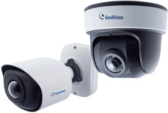
GV-PBL8800 GV-IP Panoramic Cameras
- GV-PBL8800
- GV-PDR8800
Before attempting to connect or operate this product, please read these instructions carefully and save this manual for future use.
MPA-QG-A
© 2022 GeoVision, Inc. All rights reserved.
Under the copyright laws, this manual may not be copied, in whole or in part, without the written consent of GeoVision.
Every effort has been made to ensure that the information in this manual is accurate. GeoVision, Inc. makes no expressed or implied warranty of any kind and assumes no responsibility for errors or omissions. No liability is assumed for incidental or consequential damages arising from the use of the information or products contained herein. Features and specifications are subject to change without notice.
GeoVision, Inc.
9F, No. 246, Sec. 1, Neihu Rd.,
Neihu District, Taipei, Taiwan
Tel: +886-2-8797-8377
Fax: +886-2-8797-8335
http://www.geovision.com.tw
Trademarks used in this manual: GeoVision, the GeoVision logo and GV series products are trademarks of GeoVision, Inc. Windows is the registered trademark of Microsoft Corporation.
June 2022
Scan the following QR codes for product warranty and technical support policy:
 |  |
| https://www.geovision.com.tw/warranty.php | https://www.geovision.com.tw/_upload/doc/Technical_Support_Policy.pdf |
Hardware Overview
1.1 Fixed Rugged IP Dome Camera
1.1.1 GV-PDR8800 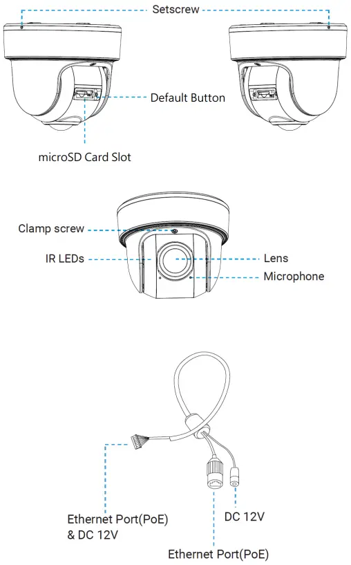 1.2 Fixed Bullet IP Camera
1.2.1 GV-PBL8800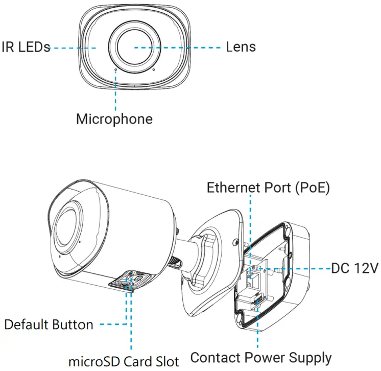
Quick Installation Steps
2.1 Fixed Rugged IP Dome Camera Installation
Loosen the setscrew and take the bracket off. 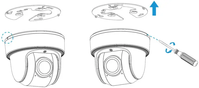 Note: There are two setscrews on the camera that fasten the bracket. Loose either one or both setscrews until the bracket can be taken off. Only one of the setscrews needs to be screwed while fixing.
Fix the bracket on the position where the camera is intended to be installed. 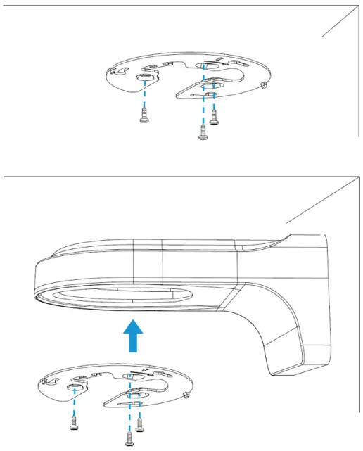 Step 1: Buckle the lanyard on the camera body tightly to the reserved hook on the bracket.
After connecting the cables to the respective connectors, twine the cables around tidily in the room on the bottom. 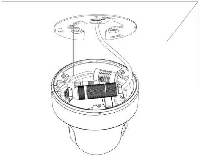 Step 2: Rotate the camera to bracket and tighten the setscrew.
 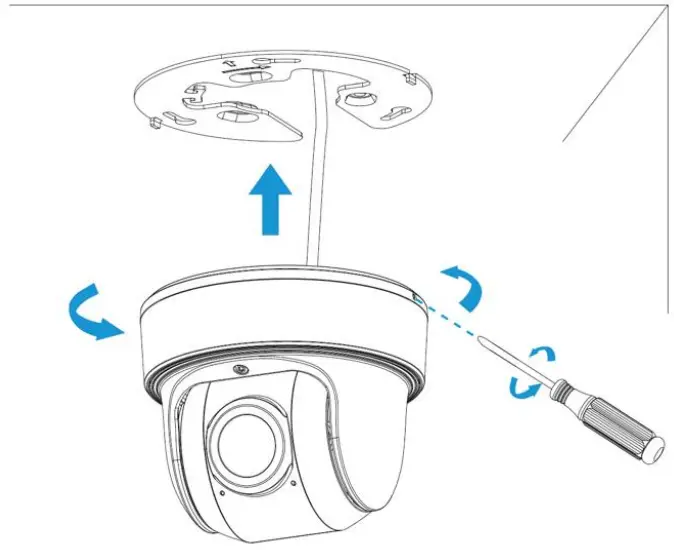 Step 3: Loosen clamp screw and adjust shooting direction, tighten clamp screw.
 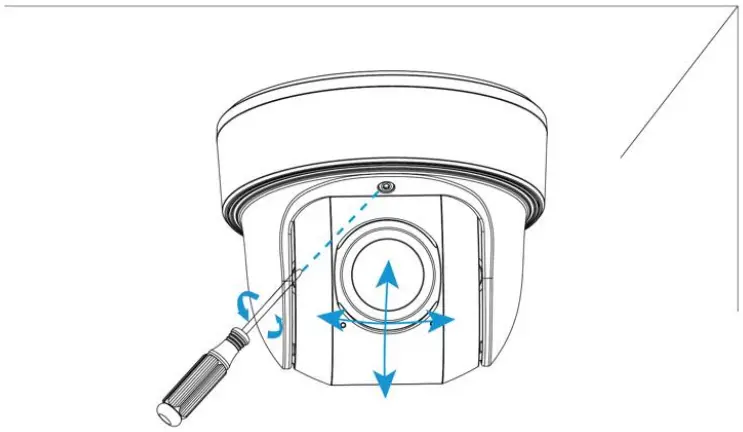 2.2 Fixed Bullet IP Camera Installation
Step 1: Connect the cables to the corresponding interface on the rear cover of the Junction Box. Then fix the rear cover on the position where it is intended to be installed. The rear cover can be fixed directly as follows: 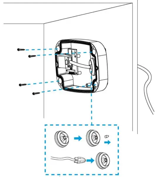 Step 2: When the front cover is correctly fixed to the rear cover, the camera will be powered on by contact power supply. Adjust shooting direction and rotate locking ring.
 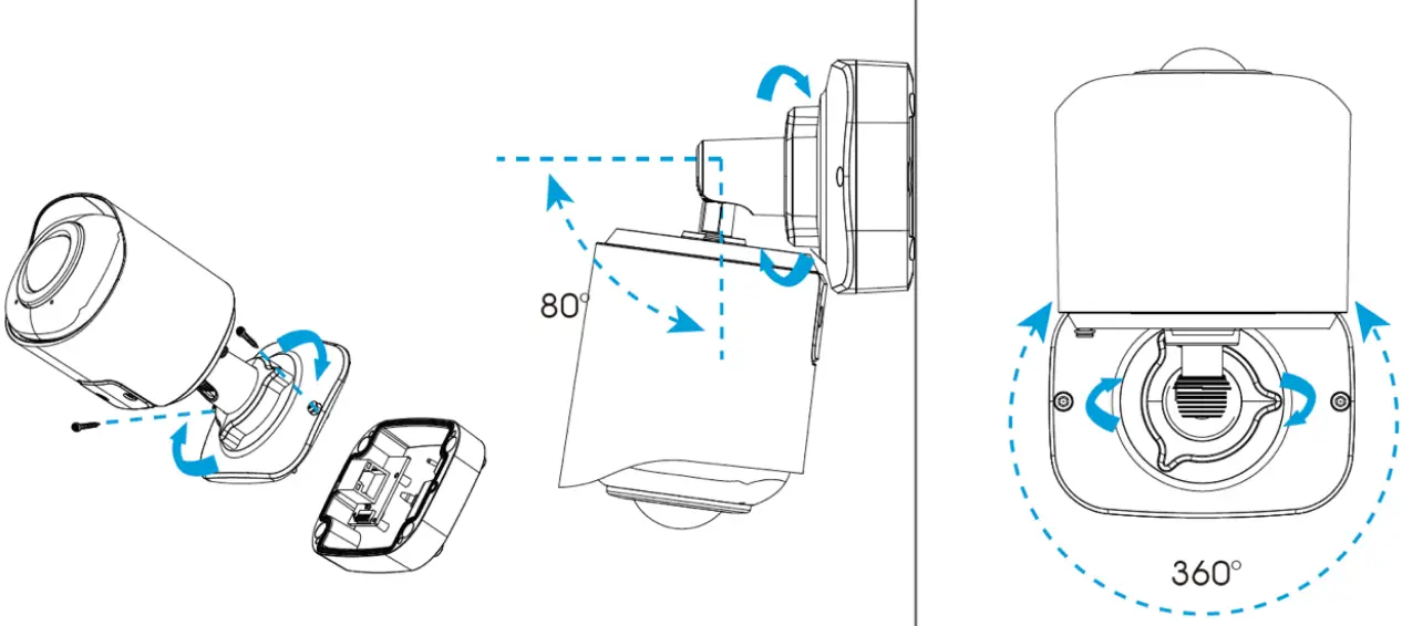 Note: Loosen the screws of SD card structure to get access to the SD card slot if you need.
Fix the screws again after inserting the SD card to complete the operation.
Waterproofing the Connector
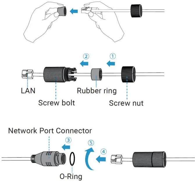 Step 1: Get the network cable through the screw nut, rubber ring and the screw bolt.
Step 2: Insert the rubber ring into the screw bolt.
Step 3: Connect the screw nut to the screw bolt.
Step 4: Place the O-Ring on the network port connector, tighten the screw bolt and the connector.
Note: Make sure to tightly wrap all cable-out interfaces with adhesive tape to protect them from water.
Accessing the Network Camera
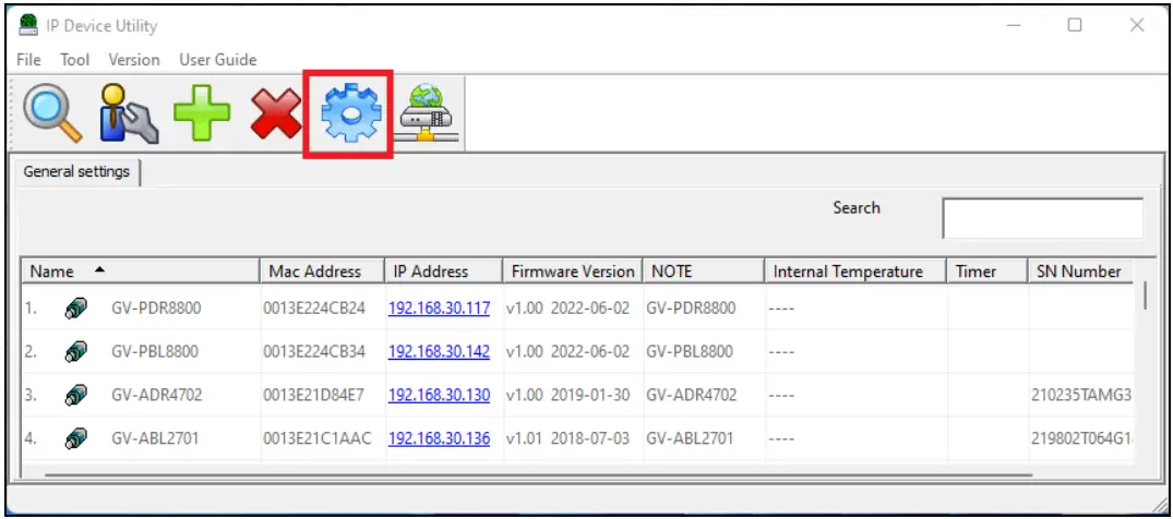
4.1 Looking Up the Dynamic IP Address
By default, when the camera is connected to LAN with DHCP server, it is automatically assigned with a dynamic IP address. Follow the steps below to look up its IP address. Note this function is only applicable on GV-IP Device Utility V8.9.7.0 or later.
- Download and install the GV-IP Device Utility program from the company website.
- On the GV-IP Utility window, click the
 button to search for the IP devices connected in the same LAN. Click the Name or Mac Address column to sort.
 - For the first-time users, select Configure to set up a password.

- Type a new password and click OK.
- Type the default username (admin) and your password on the login page and click Login.
Note:
- The computer you use to configure the IP address must be under the same LAN as your camera.
- By default, the Administrator’s username is admin and cannot be modified.
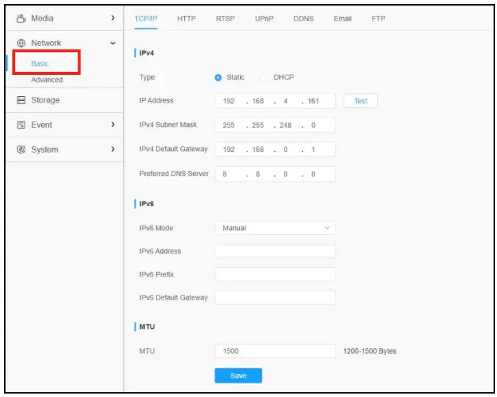
4.2 Configuring the IP Address
If the camera is connected to a LAN without DHCP server, the default IP address will be 192.168.0.10. Follow the steps below to modify the IP address to avoid IP conflict with other GV-IP devices on the same LAN.
- Open your Web browser, and type the default IP address 192.168.0.10.
- Type the default username (admin) and your password. Click Login.
- Select Static IP next to Type.

- Enter the IP address, subnet mask, and default gateway address. Make sure that the IP address of the camera is unique in the network.
- Click Save.
The Web Interface
After logging in the camera’s Web interface, the user is allowed to view live videos as follows. 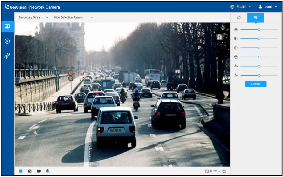
| No. | Parameter | Description |
| 1 | Click to access the live view page. | |
| 2 | Click to access the playback page. | |
| 3 | Click to access the configuration page. Note: See Chapter 8 of GV-IP Panoramic Cameras User Manual for details. | |
| 4 | Click to select system language. | |
| 5 | Display the user name and click to logout. | |
| 6 | Choose the stream (Primary/Secondary/Tertiary) to show on the current video window. | |
| 7 | Choose the options (Hide Detection Region/Region Entrance/ Region Exiting/Advanced Motion/Line Crossing/Loitering/ People Counting/Object Left/Object Remove/Regional People Counting) to hide/display detection region on the current video window. | |
| 8 | When recording, the icon appears. | |
| 9 | When an alarm of VCA event was triggered, the icon appears. | |
| 10 | When an alarm of people counting was triggered, the icon appears. | |
| 11 | When an alarm of Motion Detection was triggered, the icon appears. | |
| 12 | Except for the three kinds of alarms above, when other alarms were triggered, the icon appears. | |
| 13 | Stop/Play live view. | |
| 14 | Click to capture the current image and save to the configured path. | |
| 15 | Click to Start Recording video and save to the configured path. Click again to Stop Recording. | |
| 16 | When enabled, you can zoom in in a specific area of video image with your mouse wheel. | |
| 17 | Click to display images at a window size. | |
| 18 | Click to display images at full-screen. | |
| 19 | Click to access installation. The AI algorithm will change according to the installation (Wall algorithm/Ceiling algorithm). | |
| 20 | Brightness: Adjust the Brightness of the scene. Contrast: Adjust the color and light contrast. Saturation: Adjust the saturation of the image. Higher saturation makes colors appear “purer” while lower one appears more “washed-out”. Sharpness: Adjust the sharpness of image. Higher sharpness sharpens the pixel boundary and makes the image look “clearer”. 2D DNR/3D DNR: Adjust the noise reduction level. Default: Restore brightness, contrast and saturation to default settings. Note: See 8.1.2 Image of GV-IP Panoramic Cameras User Manual for details. |
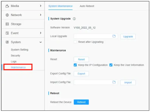
Upgrading System Firmware
GeoVision periodically releases updated firmware on the company website. To load the new firmware into the camera, follow the instructions below.
- At the top, select System > Maintenance > System Maintenance. This page appears.

- Click the
 button under System Upgrade to locate the firmware file saved at your local computer.
 - Click Upgrade to process the upgrade.
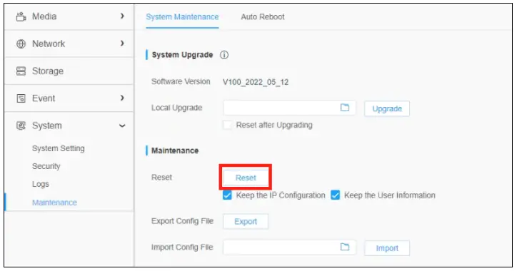
Restoring to Factory Default
If for any reason the camera is not responding correctly, you can restore the camera back to its factory default settings using the Web interface or the Default Button.
- On the Web interface, click Settings.
- In the left menu, select System and select Maintenance.
- At the top, select System Maintenance.
- Under the Maintenance section, click Reset.
![]()


