Jandy H0754600 TruDose Chemical Controller User Guide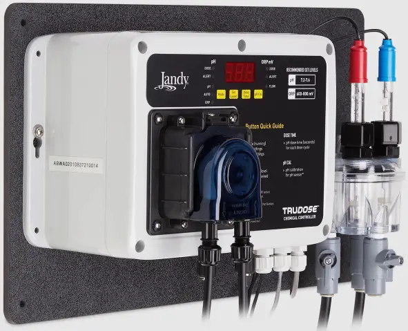
WARNING
This device is for use with single-body swimming pool applications only. Not for use with dual-body pool and spa applications, or stand-alone spas. Use of this product with dual-body pool and spa applications or stand-alone spas may cause severe injury, property damage, and void the warranty.
To prevent risk of electrical shock which can result in severe injury or death, ENSURE that the controller is OFF and power to the controller is disconnected before proceeding with installation. To reduce the risk of electric shock, fire or injury, service should only be attempted by a qualified pool service professional.
FOR YOUR SAFETY This product must be installed and serviced by a contractor who is licensed and qualified in pool equipment by the jurisdiction in which the product will be installed where such state or local requirements exist, the maintainer must be a professional with sufficient experience in pool equipment installation and maintenance so that all of the instructions in this manual can be followed exactly. Before installing this product, read and follow all warning notices and instructions that accompany this product. Failure to follow warning notices and instructions may result in property damage, personal injury, or death. Improper installation and/ or operation may void the warranty. Improper installation and/or operation can create unwanted electrical hazard which can cause serious injury, property damage, or death. DO NOT MODIFY THIS EQUIPMENT.
This device complies with part 15 of the FCC Rules. Operation is subject to the following two conditions: (1) This device may not cause harmful interference, and (2) this device must accept any interference received, including interference that may cause undesired operation. CAN ICES-003(B) / NMB-003 (B).
MAINTENANCE
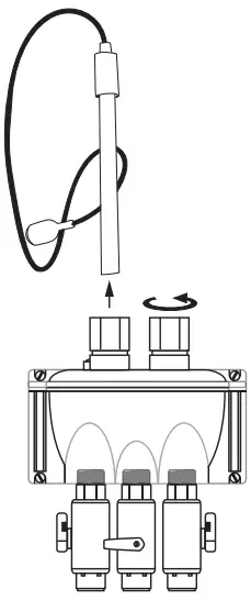
Sensor Cleaning
- Close flow cell valves in order to isolate it.
- Loosen nut and remove sensor from flow cell.

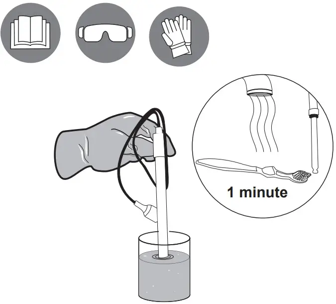
- Brush sensor tip for 1 minute.
- 50 ml (2 oz) tap water + 1 mL (10 drops) muriatic acid, then soak for 2 minutes.
- Rinse with clean water for 1 minute. Shake off excess water.

- Reinsert sensor and hand- tighten the nut. Then connect sensor to controller, matching the sensors and labels colors (Blue = pH and red = ORP).

Check pH and ORP Sensors every 6 months
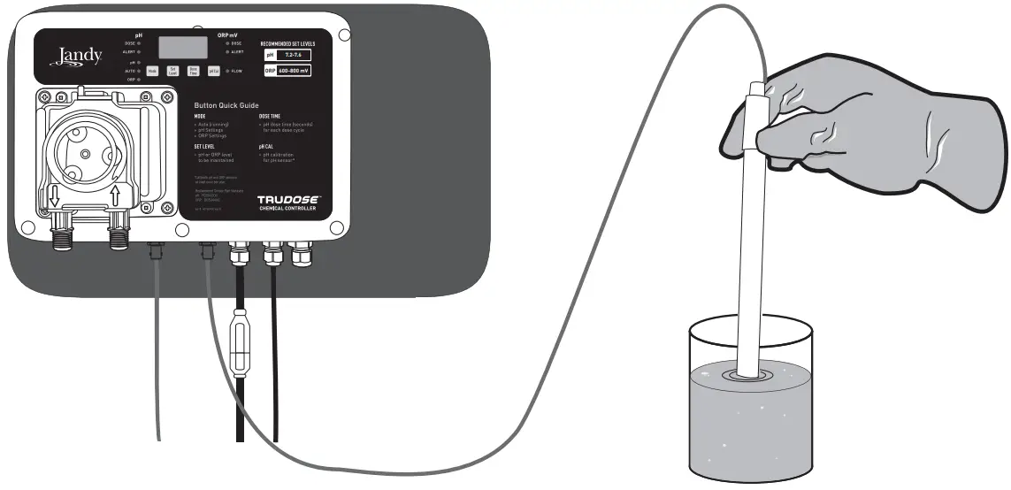
pH:
Add muriatic acid or vinegar and check for low reading.
- Place sensor in solution 7.5 pH or higher to verify reading is increasing.
ORP:
Place clean sensor tip into tap water = 200 – 400 mV reading. Add Dichlor or Trichlor = 750 – 800 mV.
NOTE: High pH sanitizer instead of Dichlor/Trichlor = 650 – 750 mV reading.
Tubing Replacement
Remove power to unit by unplugging power supply and flush line before servicing. AVOID CONTACT WITH EXPELLED LIQUID
![]() WARNING
WARNING
Personal Protective Equipment required.
Unlock Cover Latch
Slide Cover Up and Off
Remove and Replace Tubing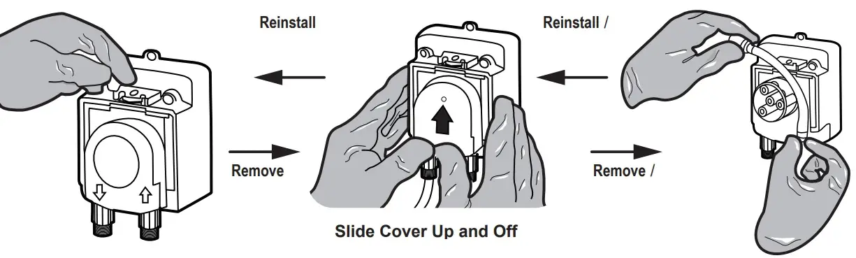
*Reverse step to install new tubing and secure cover.
SETTINGS GUIDE
AUTO
Normal – full operation and monitoring of pH and ORP, no pushbuttons available.
| pH | ||||
| Set Level | Default | 7.4 pH | Selectable Range | 7.0 – 8.0, 0.1 increments |
| Dose Timer | Default | 30 seconds feeding ON, 5 min. feed delay | Selectable Range | OFF; Timed: 10 – 900 ON, 5 min. OFF |
| Overfeed Timer (Er1) | Default | 60 timed cycles | Reset: Turn OFF then ON, or Press MODE repetitively to cycle from AUTO to next AUTO in sequence | |
| High Alert | Default | 8.1 pH | pH Alert LED ON | |
| Low Alert | Default | 6.9 pH | pH Alert LED ON | |
| pH Cal | Default | +/- 0.5 pH from current reading, 0.1 increments | ||
| ORP | ||||
| Set Level | Default | 700 mV | Selectable Range | 400 – 900 mV with 10 mV increments |
| Dosing Strateg | Default | 24 VDC relay ON to saltwater chlorinator until setpoint/overtime feeder reached (optional) | ||
| Overfeed Timer (Er2) | Default | ON after 36 hours w/o reaching ORP setpoint | Selectable Range | 12 – 96 hours, 12 hour increments |
| High Alert | Default | 910 mV | ORP Alert LED ON | |
| Low Alert | Default | 390 mV | ORP Alert LED ON | |
FLOW:
Flow switch pre-wired to controller. NOTE: Required to prevent dosing when no circulation fl ow. Require installation of inline Filter on intake tubing for proper operation of fl ow switch.
FACTORY DEFAULTS:
Place in Standby mode. Press and hold both SET LEVEL and pH CAL buttons, then press MODE. pH and ORP displays “Ld” and in test mode. Full operation: Press MODE to turn OFF and press MODE to turn on TruDose controller.
SHUT DOWN:
Press and hold MODE for 2 seconds until pH and ORP displays “OFF”. Green Flow LED is lit while water is flowing through fl ow cell.
BEFORE YOU START
This Quick Start Guide contains essential installation and start up instructions. Read the complete manuals and all safety warnings accompanying this system before commencing installation.
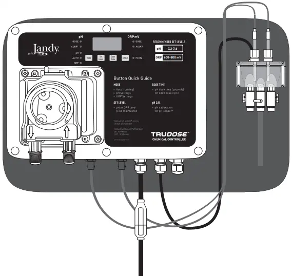
CONTROLLER ADJUSTMENTS
| pH LEDs | |
| pH Alert | Solid RED |
| pH Overfeed Alarm | Blinking RED – “Er1” display |
| pH Dose – Running | Flashing GREEN |
| pH Dose – Time Off | Solid GREEN |
| ORP LEDs | |
| ORP Alert | Solid RED |
| ORP Overfeed Alarm | Blinking RED – “Er2” display |
| ORP Dose – Timer On | Flashing GREEN |
| Mode | |
| AUTO | Red LED |
| pH Settings | Green LED |
| ORP Settings | Yellow LED |
| OFF Mode | Press and hold  for 3 seconds for 3 seconds |
| Flow |  |
| Set Level |  |
| Dose Time |
|
| pH Cal |  |
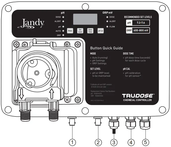
| Electrical Connections | |
| pH Sensor | 1 |
| ORP Sensor | 2 |
| AC Power | 3 |
| Flow Cell | 4 |
| Saltwater Chlorinator Control | 5 |
TOOLS NEEDED
- Safety Googles

- Acid Resistant Gloves
- Cordless Drill
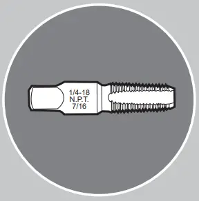
- 1/4 NPT Tap (included)
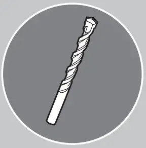
- 7/16” Drill Bit
- Masonry Drill Bit
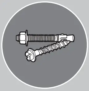
- Masonry Anchors/ Fasteners
- 13/16” Channel Lock Pliers
- Watertight Outlet Cover
- 5 Gallon Acid Resistant Tank


Read the complete manuals and all safety warnings accompanying this system before commencing installation.
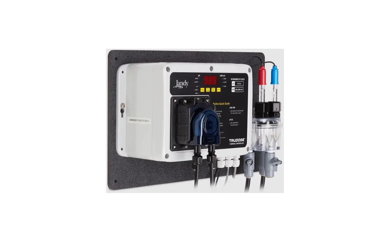
SYSTEM COMPONENTS
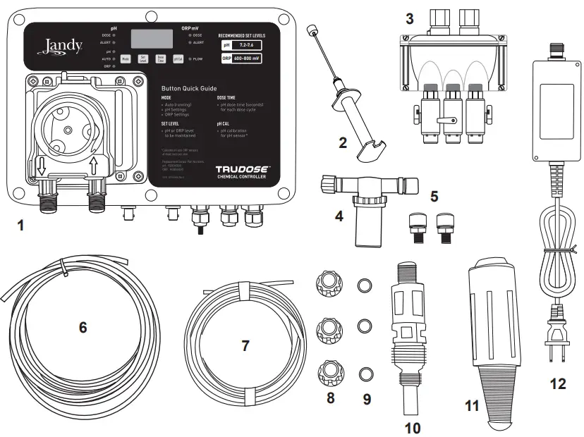
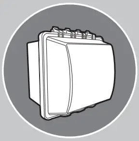
- TruDose Controller
- pH and ORP Sensors
- Flow Cell
- Inline Filter
- Compression Fittings
- 3/8” Tubing
- 1/4” Tubing
- 1/4” Connecting Nuts
- 1/4” Ferrules
- Injection Valve
- 1/4” Weighted Suction Line Strainer
- Power Supply Transformer
INSTALLATION
Mechanical
- Plug controller into an outdoor-rated GFCI-protected electrical outlet with weather cover (see Note*).
- Install mounted TruDose controller.
- Install pH and ORP sensors in the fl ow cell and connect the BNC connectors to the TruDose controller.
- Install inline Filter on tubing from return line to fl ow cell.
- Install 3/8” tubing to suction line from fl ow cell.
- Install 1/4” suction line tubing from acid tank to chemical pump (muriatic acid 4:1 dilution).
- Install injection check valve on tubing from chemical pump to return line.
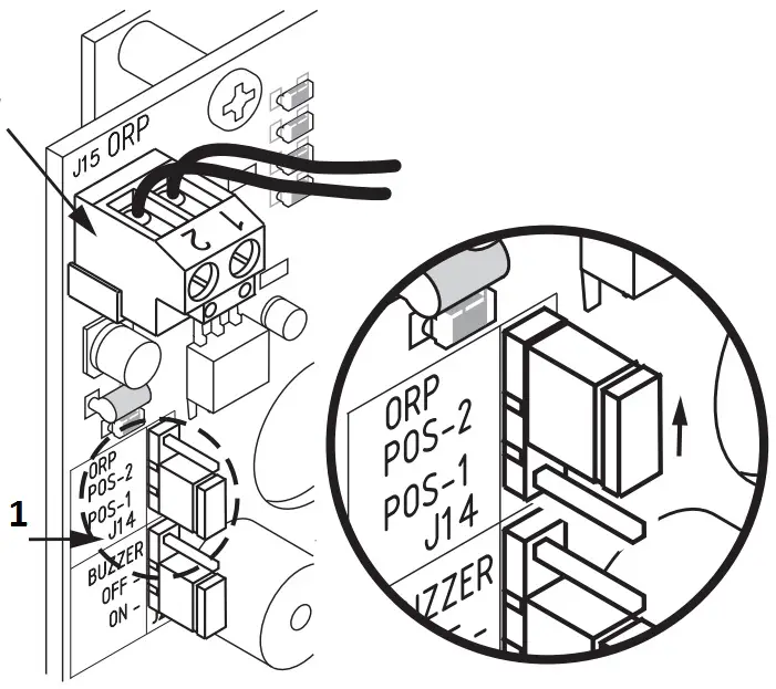
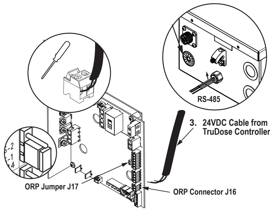
Electrical
| Jumper ORP (J14 / J17) on POS2 | When TruDose is supplying 24 VDC | When TruDose is supplying 0 VDC |
| Chlorination | ON | OFF |
| Display on APUREM and TRUCLEAR XL | 0-100% | EC “external control” |
| Jumper | Type/System PCB / Type | Action |
| J14 | ORP jumper on AquaPure | Move to Position 2 |
| J15 | ORP connector on AquaPure | Insert 24 VDC cable here |
| J16 | ORP connector on TruClear XL | Insert 24 VDC cable here |
| J17 | ORP jumper on TruClear XL | Move to Position 2 |
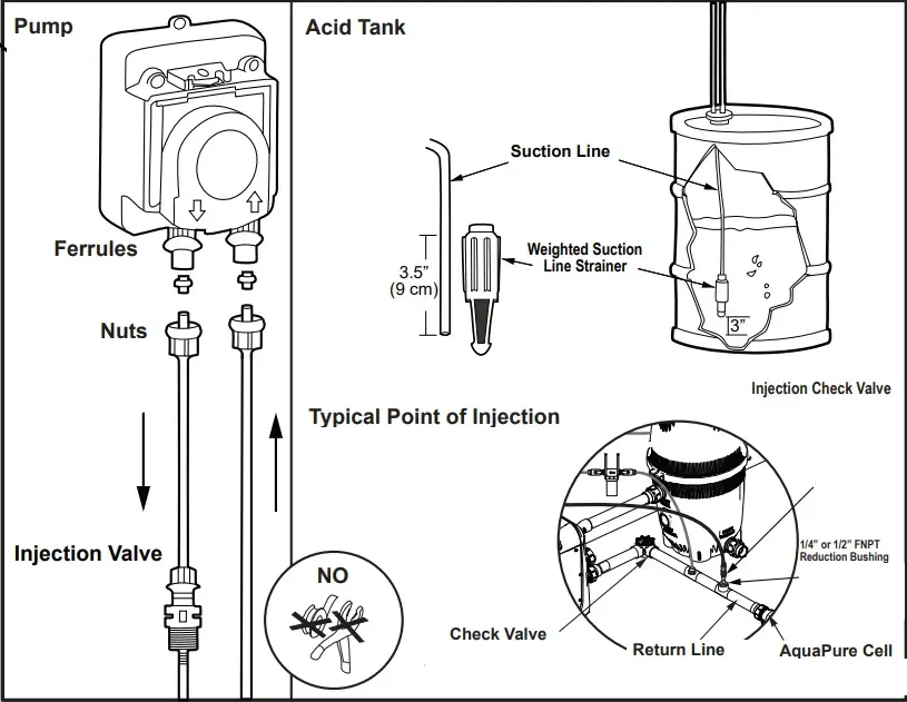
Chemical Pump Connection
1 | Suction Line to Pump Head (see Figure 3a – step F, Figure 3c) |
| 2 | Weight to Suction Line (see Figure 3a – step F, Figure 3c) |
3 | Pump Head Discharge Line to Injection Point (see Figure 3a – step G, Figure 3c) |
Only power with the provided power supply. Install power supply and controller at least 5 feet (3 meters for Canada) away from the inside edge of the pool and/or spa.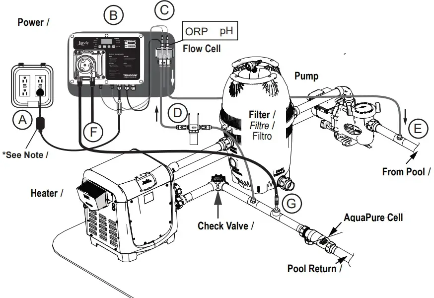
NOTE
Mount power supply transformer 1ft (30 cm) above ground surface
APUREM
ORP Connector J15 R0474300
- Remove ORP Jumper J14
- Connect ORP connector from TruDose
- Shift up (jumper)

TruClear® XL
- Push TruDose Cable through
- Remove Connector from pre-installed 24VDC Cable
- Shift down
- 24VDC Cable from TruDose Controller


Support
©2022 Zodiac Pool Systems LLC
All rights reserved. ZODIAC® is a registered trademark of Zodiac International, S.A.S.U. used under license. All other trademarks referenced herein are the property of their respective owners.
Zodiac Pool Systems LLC
2882 Whiptail Loop # 100, Carlsbad, CA 92010
1.800.822.7933 | Jandy.com
Zodiac Pool Systems Canada, Inc.
3365 Mainway, Unit 2 Burlington, ON L7M 1A6
1-888-647-4004 | Jandy.ca


