![]() DNL.WHS.23800 GEN II CANsmart Controller
DNL.WHS.23800 GEN II CANsmart Controller
Instruction Manual
Thank you for choosing DENALI
We know you would rather be riding your bike than wrenching on it, so we go the extra mile to make sure our instructions are clear and as easy to understand as possible. If you have any questions, comments, or suggestions don’t hesitate to give our experts a call at 401.360.2550 or visit WWW.DENALIELECTRONICS.COM
Please Read Before Installing
DENALI products should always be installed by a qualified motorcycle technician. If you are unsure of your ability to properly install a product, please have the product installed by your local motorcycle dealer. DENALI takes no responsibility for damages caused by improper installation. Caution: When installing electronics it is extremely important to pay close attention to how wires are routed, especially when mounting products to the front fender, front fork, or fairing of your motorcycle. Always be sure to turn the handlebars fully left, fully right, and fully compress the suspension to ensure the wires will not bind and have enough slack for your motorcycle to operate properly.
Installation Tips
We strongly recommend using a medium-strength liquid thread locker on all screws and bolts. It is also important to ensure that all hardware is tightened to the proper torque specifications as listed in your owner’s manual. For included accessory hardware please refer to the default torque specifications provided below. Inspect all hardware after the first 30 miles to ensure that proper torque specifications are maintained.
| Bolt Size | in-lbs | ft-lbs | Nm |
| M3 | 10.0 in-lbs | – | 1.0 Nm |
| M4 | 23.0 in-lbs | – | 2.5 Nm |
| M5 | 44.5 in-lbs | 3.5 ft-lbs | 5.0 Nm |
| M6 | 78.0 in-lbs | 6.5 ft-lbs | 9.0 Nm |
| M8 | – | 13.5 ft-lbs | 18.0 Nm |
| M10 | – | 30.0 ft-lbs | 41.0 Nm |
| M12 | – | 52.0 ft-lbs | 71.0 Nm |
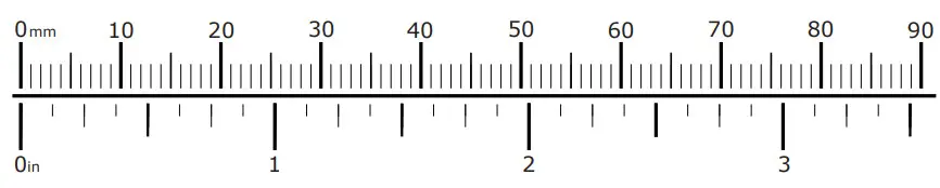
Hardware Sizing Guide
Not sure what size bolt you have? Use this ruler to measure screws, bolts, spacers, etc.
Remember, the length of a screw or bolt is measured from the start of the “mounting surface” to the end of the screw, so only include the screw head when measuring countersunk screws.
What’s In The Box?
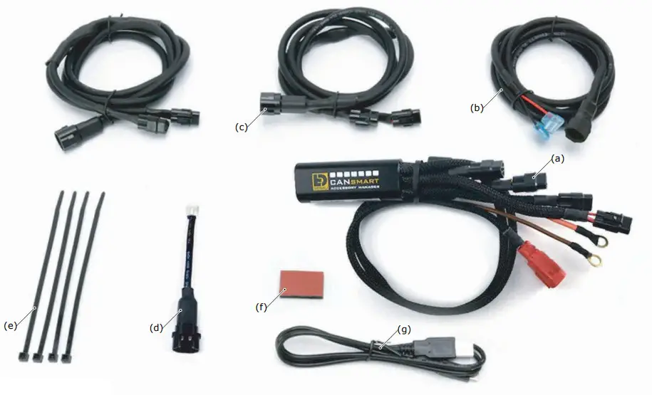
Kit Contents
(a) CANsmart™ Controller………………………………………………….Qty 1
(b) 3-Pin 5ft Horn Extension……………………………………………….Qty 1
(c) 3-Pin 5ft LED Light Extension………………………………………….Qty 2
(d) 3-Pin Brake Light Wiring Adapter……………………………………..Qty 1
(e) Zip Tie…………………………………………………………………….Qty 4
(f) Adhesive Dual Lock……………………………………………………..Qty 1
(g) USB to Micro USB Programming Cable……………………………….Qty 1
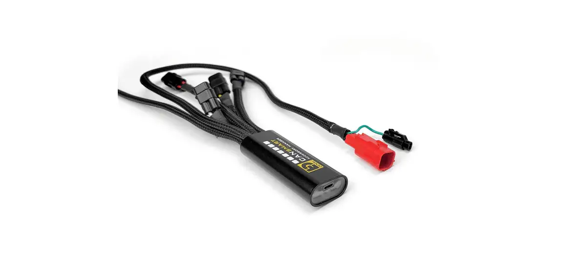
1.1 – Overview of Device
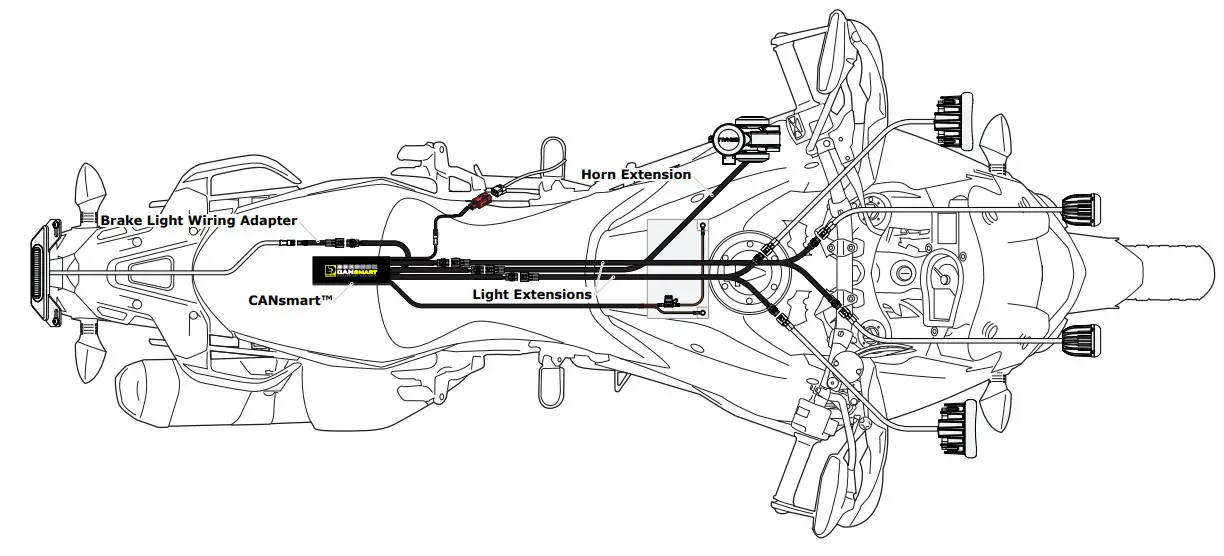
The DENALI CANsmart™ Controller provides plug-n-play installation and integrated control of up to four accessories to enable dozens of customizable settings that can be controlled right from the Vehicles Controller or the CANsmart™ Accessory Manager Software.
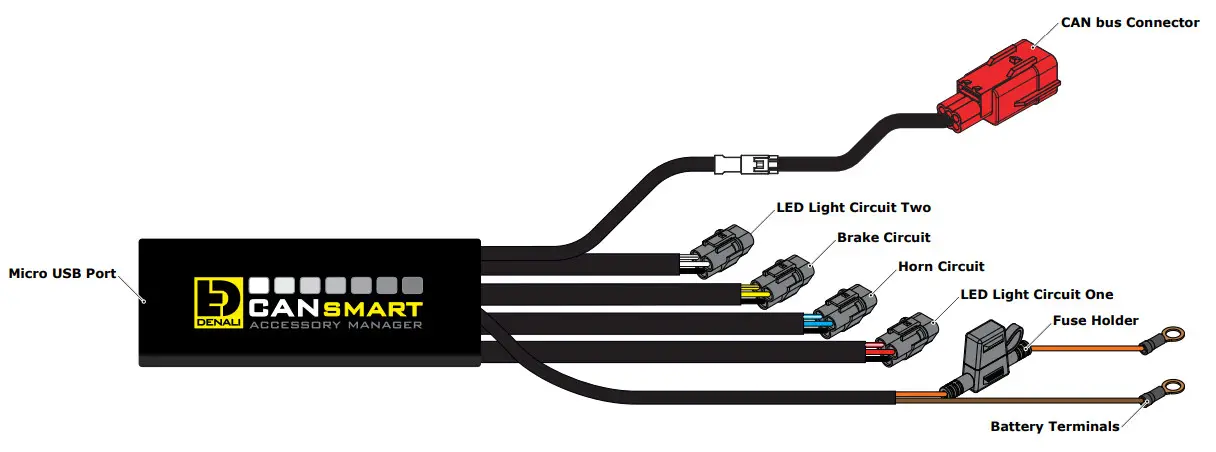
The four circuits are pre-programmed to connect and independently control two sets of DENALI 2.0 lights, a SoundBomb horn, and our B6 auxiliary brake light. However, our Circuit Function Selector in the CANsmartsoftware will let you run any accessory of your choice on any of the four circuits.
The illustration above depicts the preprogrammed default configuration, to see all available circuit functions and settings please refer to Section 6 or visit our online user guide at: DENALIelectronics.com/cansmart-user-guide
1.2 – Overview of System Features
The two auxiliary light circuits enable independent adjustment of high and low beam brightness right from the vehicle’s factory controls It also features a “flash to pass” and “strobe when horn active” setting that will strobe the auxiliary lights when you pulse your high beam switch or sound your horn.
The feature-rich brake light circuit will transform a simple 2-wire brake light into a “smart brake light” complete with running light, multiple flash patterns, and deceleration-activated braking functionality.
The horn circuit enables the addition of an auxiliary horn without having to add a relay and dedicated horn wiring harness.
For a full list of features and available settings refer to Section 6.
Connecting To CAN bus
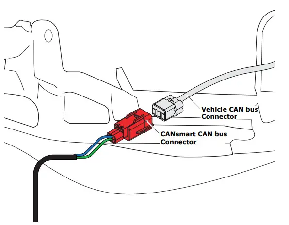
2.1 – Connecting To The CAN bus
Step One: Locate your bike’s Diagnostic Port. The port is a red 6-pin female connector. In general, the connector is located underneath the rider’s seat. For the exact location, check your bike owner’s manual.
Step Two: Remove the cap.
Step Three: Next connect the male CAN bus connector on the CANsmart™ Controller to the Diagnostic Port.
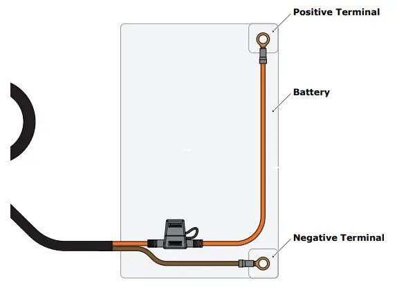
2.2 – Connecting To The Battery
Step One: Remove the fuse from the fuse holder.
Step Two: Gain access to the vehicle’s battery and disconnect the negative (-) and positive (+) terminals.
Step Three: Connect the CANsmart™ wiring harness to the battery via the ring terminals. Be sure the orange wire lead with the fuse holder goes to the positive (+) terminal of the battery.
Step Four: Re-install the fuse into the fuse holder.
Note: Place the fuse holder in an easily accessible location for convenient service in the event of a blown fuse. Light Extensions
Connecting Accessories
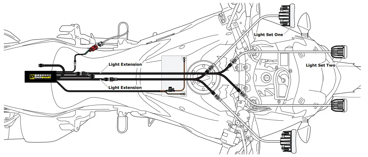
3.1 – Light Set One & Two (Red & White Circuits)
In the default configuration, the circuit for Light Set One is the longest red lead, the shortest white lead is for Light Set Two. Both circuits are designed to handle up to 15 amps each.
Step One: Plug the male 3-pin connector of the Light Extension-Splitter into one of the CANsmart™ Controller’s light circuits.
Step Two: Begin routing the harness toward the front of the bike. Secure the harness to the vehicle’s frame along the way with the included zip ties.
Be sure to avoid any moving components such as radiator fan blades or suspension.
Step Three: Plug the DENALI Light Pods into the female 3-pin connectors of the Extension-Splitter.
Repeat steps One through Three using a second Light Extension-Splitter for the second set of lights.
Two-Wire Dimming: Turn off “Three-Wire Dimming Mode” for correct dimming operation of auxiliary LED lights that have only two wires.
If enabled the 3rd yellow wire will be deactivated and PWM data will instead be transmitted through the red wire.
Wire two wire lights using the red wire for positive (+) and the black wire for negative (-).
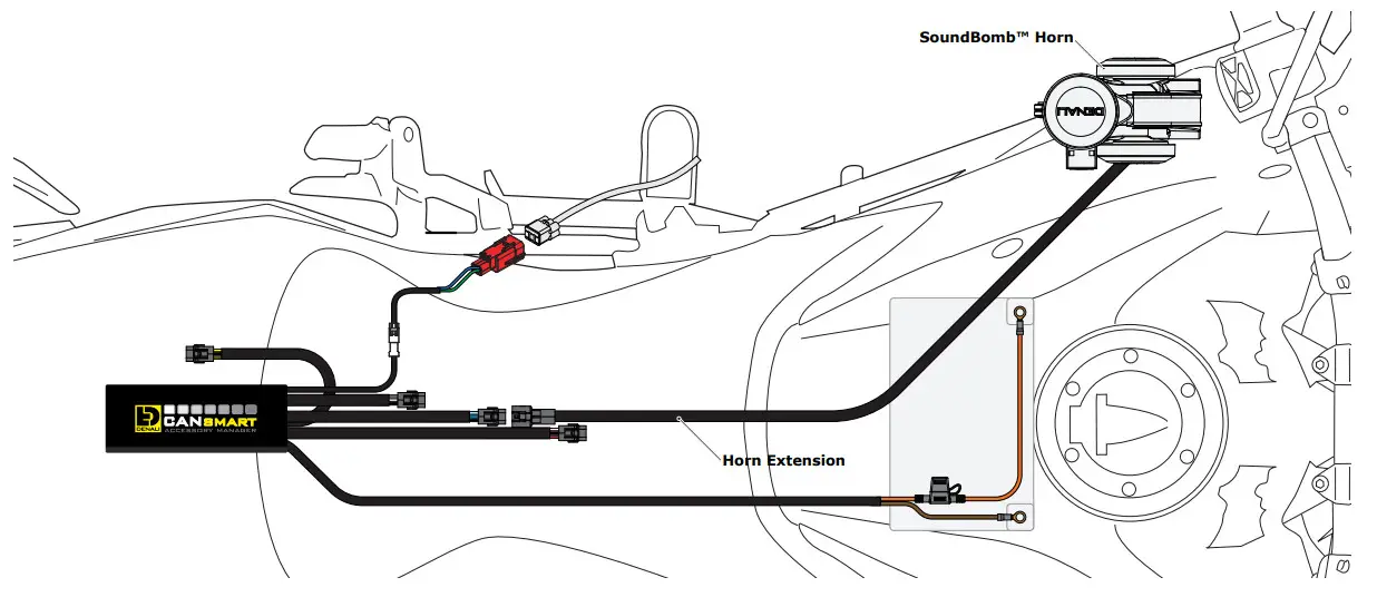
3.2 – Horn (Blue Circuit)
Step One: Plug the male 2-pin connector of the Horn Extension into the blue horn circuit on the CANsmart™ Controller.
Step Two: Begin routing the harness toward the front of the bike.
Secure the harness to the vehicle’s frame along the way with the included zip ties. Be sure to avoid any moving components such as radiator fan blades or suspension.
Step Three: Plug the spade connectors of the Horn Extension into the DENALI SoundBomb Horn. The Green wire connects to the positive (+) terminal on the horn, the Black wire goes to the negative (-) terminal.
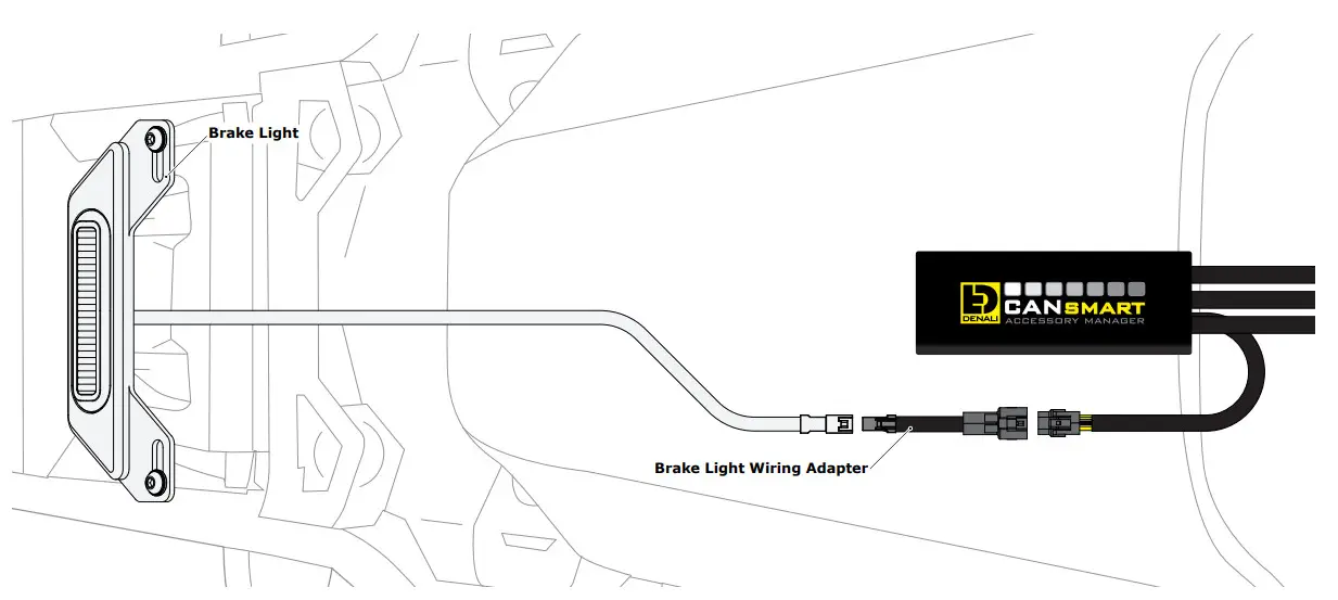
3.3 – Brake Light (Yellow Circuit)
Step One: Route the harness of the DENALI B6 Brake Light from the rear of your motorcycle toward the CANsmart™ Controller.
Step Two: Plug the Brake Light Pigtail into the connector on the DENALI B6 Brake Light.
Step Three: Plug the male 2-pin connector of the Brake Light Pigtail into the yellow brake light circuit on the CANsmart™ Controller.
Alternate Light Wiring Options
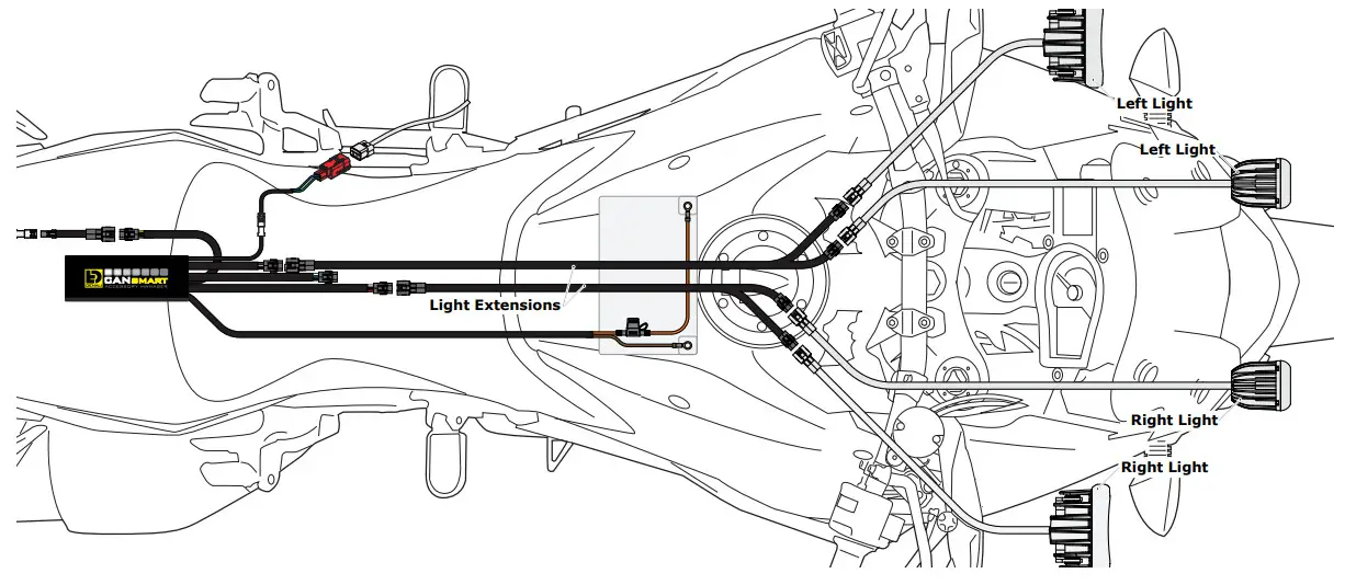
4.1 – Left/Right Split Lights
Wiring your LED Lights split left/right enables the “Off When Turn Signal Active” feature to cancel only the LED lights on the corresponding side of the bike that the signal was activated. When lights are wired assets (Figure 3.1), the LED lights on both sides of the bike will cancel regardless of which side turn signal is activated.
One: Plug the male 3-pin connector of the Light Extension-Splitter into one of the CANsmart™ Controller’s light circuits.
Step Two: Begin routing the harness toward the front of the bike. Secure the harness to the vehicle’s frame along the way with the included zip ties.
Be sure to avoid any moving components such as radiator fan blades or
Step Three: Plug the DENALI Light Pods from the right side of the motorcycle into the female 3-pin connectors of the Extension-Splitter. Repeat steps One through Three using a second Light Extension-Splitter for the lights on the left side of the motorcycle
Step Four: Connect the smart to the Device Manager Software.
Using Circuit Function Selector, reassign the circuits used to be “Left Light 1” for the circuit powering the left side LED lights, and “Right Light 1” for the circuit powering the right side LED lights.
Software Overview
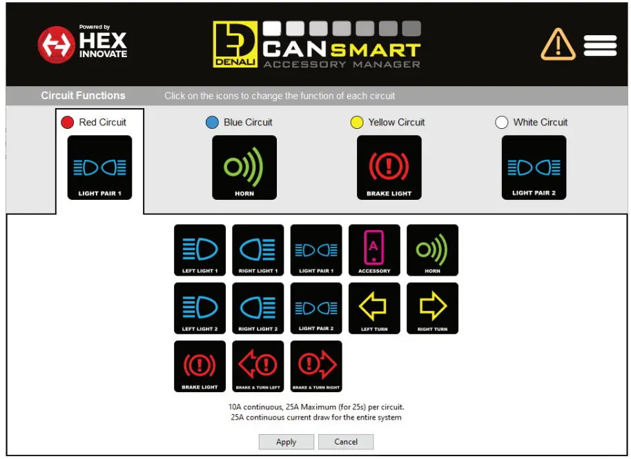
5.1 – Circuit Function Selector
The Circuit Function Selector in the CANsmart software will let you run any accessory of your choice on any of the four circuits. Click on a circuit icon to open the drop-down menu and make your selection from the list of available circuit functions. Continue reading for an overview of each circuit function and its available settings.
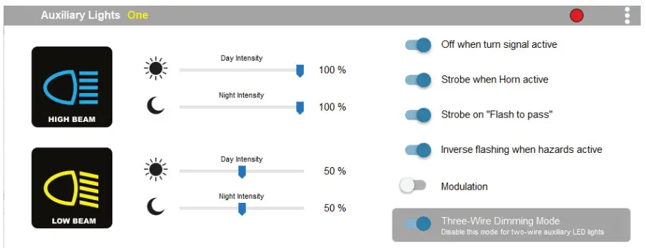
5.2 – Auxiliary Lights One (Pair or Split)
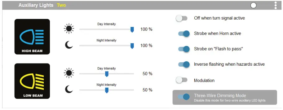
5.3 – Auxiliary Lights Two (Pair or Split)
Available settings include “Off when turn signal active”, Flash when turning signal active”, “Strobe when horn active”, “Strobe on flash to pass”, “Inverse flashing when hazards active” as well as “Modulation”. “Three-Wire dimming mode” can be turned off to properly dim LED lights which do not have a dedicated 3rd dimming wire. From the extra settings window, you can adjust the “Strobe Intensity” as well as the “Modulation variation”.
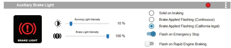
5.4 – Auxiliary Brake Light
The feature-rich Auxiliary Brake Light circuit function will transform a simple 2-wire brake light into a “smart brake light” complete with running light, multiple flash patterns, and deceleration-activated braking functionality. From the extra settings window, you can also adjust the “Brake Flashing Travel Speed” as well as the “Deceleration activated braking sensitivity”.
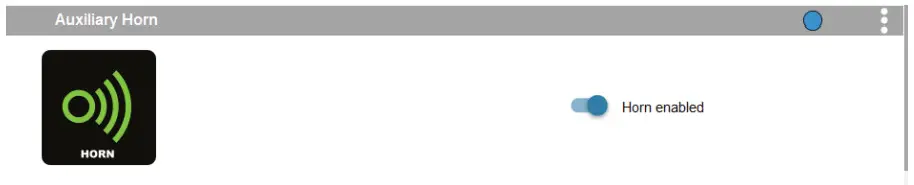
5.5 – Auxiliary Horn
The horn circuit enables the addition of an auxiliary horn without having to add a relay and dedicated horn wiring harness.
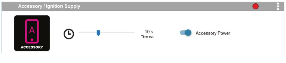
5.6 – Accessory
The Accessory circuit function will provide simple switched 12v power to an accessory of your choice when the motorcycle’s ignition is turned on. Additionally, a time-out can be set from 0-60 seconds, which determines how long the accessory circuit will remain on after the motorcycle’s ignition is turned off. The 3rd “data” wire always turns off instantly with ignition.
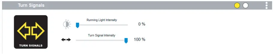
5.7 – Turn Signals
The turn signal circuit enables the addition of auxiliary turn signals without having to tap into the bike’s factory turn signal harness.
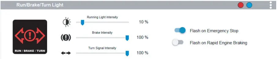
5.8 – Run/Brake/Turn
The run/brake/turn signal circuit enables the addition of auxiliary run brake turn signals complete with flash patterns, all without having to tap into the bike’s factory turn signal or brake harness.
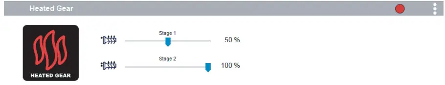
5.9 – Heated Gear
The heated gear circuit enables heated gear to work in conjunction with the motorcycle’s factory heated grip settings. The temperature of the heated gear can be adjusted from 0%-100% for each stage the motorcycle has for the factory heated grips.
5.10 – Where To Download The Software
The CANsmart™ Accessory Manager Software is available for both Windows and Mac operating systems. To download your copy please visit
WWW.DENALIELECTRONICS.COM/KTM
5.11 – Connecting The Device To The Software
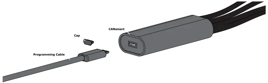
Step One: Remove the protective cap from the micro USB port on the end of the CANsmart™ Controller.
Step Two: Plug the provided programming cable into the CANsmart™ Controller, and plug the other end into your computer’s USB port.
Step Three: Open the smart Accessory Manager Software and turn the motorcycle’s ignition to the “ON” position.
Controlling Via The Motorcycle
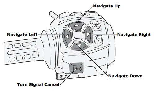
6.1 – Pan America Left Hand Controls
The Auxiliary Light will be controlled via the factory left-hand side handlebar combination switch. The Left, Right, Up, and Down Navigation buttons and the Turn Signal Cancel button will be used to control the lights. See the table below for operation details.
6.2 – Pan America CANsmart Operation
| Auxiliary Light Set One | |
| On/Off | Press and hold the “Turn Signal Cancel” button for 3 seconds |
| Enter WonderWheel Dimming Mode | Hold the “Navigate Left” button for 3 seconds |
| Adjust Intensity | Use “Navigate Up” & “Navigate Down” buttons to adjust between 0% to 100% in 10% increments |
| Exit WonderWheel Dimming Mode | Wait for 5 seconds time out |
| Auxiliary Light Set Two | |
| On/Off | Rapidly press the “Turn Signal Cancel” button 3 times |
| Enter WonderWheel Dimming Mode | Hold the “Navigate Right” button for 3 seconds |
| Adjust Intensity | Use “Navigate Up” & “Navigate Down” buttons to adjust between 0% to 100% in 10% increments |
| Exit WonderWheel Dimming Mode | Wait for 5 seconds time out |
| Auxiliary Horn | |
| Sound Auxiliary Horn | Press the vehicle’s original horn button |
| Auxiliary Brake Light | |
| Activate Auxiliary Brake Light | Apply vehicles front or rear brakes (Can be set to flash upon deceleration) |
| Auxiliary Turn Signals | |
| Activate Auxiliary Turn Signals | Activate the vehicle’s original left or right turn signals. |
| Heated Gear | |
| On/Off | Activate the vehicle’s original heated grips |
| Adjust Heat | Change the power level of the vehicle’s original heated grip |
Troubleshooting Guide
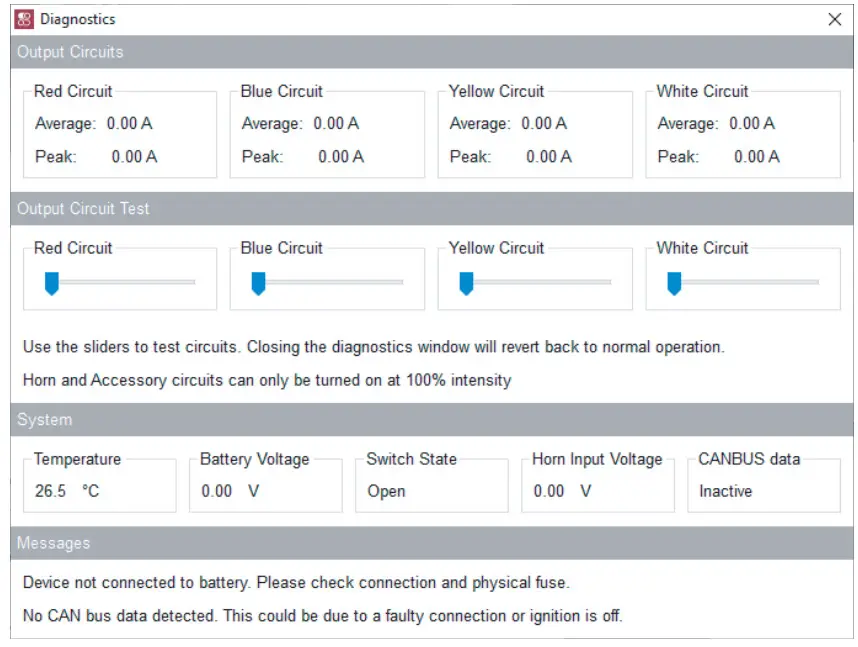
8.1 – Diagnostics Windows
The Diagnostics Window can be opened from the main menu. Use this window to get an overall view of the system’s power consumption, as well as Battery/CAN bus voltage and device temperature.
Each circuit can be tested by sliding the slider underneath the circuit name.
The unit must be connected to the battery or another source of 12V DC power in order to use the circuit test feature. The circuits will revert to normal operation when the diagnostics window is closed.
CANsmart™ Status Indicator Light Key
| LED Color | Status | Solution |
| Solid Green | Normal operation, no errors present. (Vehicle Ignition ON) | N/A |
| Slow Flashing Green | Normal operation, no errors present. (Vehicle Ignition OFF) | N/A |
| Quick Flashing Green | Bootloader Mode (Should only be seen during firmware upgrade) | Connect to software, should reset into normal operation |
| Solid Red | Recovered from an unexpected failure | Connect to software, should attempt to reset to normal operation. Please report the exact circumstances to DENALI for analysis. |
| Flashing Red | At least one channel’s electronics fuse has been tripped. | Check/Increase fuse settings, cycle ignition to reset electronic fuses |
| Solid Green & Flashing Red | Application Firmware Corrupt | Connect to software, should offer an upgrade/recovery |
| Solid Red & Solid Green | The device has been deactivated | Return to DENALI for analysis. Please send log files info©DENALIelectronic.com for analysis by DENALI. |
| Flashing Red & Flashing Green | Data/configuration fault. (missing CAN bus data) | Check that the correct CAN bus connector was used. If the problem persists please send log files to info©DENALIelectronics.com for analysis by DENALI |
8.2 – Status Indicator Light
The smart controller features a LED status indicator light, the light is located next to the micro USB programming port. The chart above defines each of the LED colors/flash patterns and provides possible solutions to any faults that are present in the system.
8.3 – Online Trouble Shooting Guide
For the most up-to-date comprehensive troubleshooting guide, please visit DENALIelectronics.com/Harley-Davidson
GEN II CANsmart™ Controller
DNL.WHS.23800
Harley-Davidson Pan America 1250
Harley-Davidson Pan America 1250 Special
References
 DENALI Electronics - LED Lights, CANsmart Controllers, Horns, & More
-
DENALI CANsmartâ„¢ - The Best CANbus Controller On The Market – DENALI Electronics
-
Harley-Davidson CANsmart Controller – DENALI Electronics
-
DENALI Electronics - LED Lights, CANsmart Controllers, Horns, & More
-
KTM CANsmart Controller – DENALI Electronics


