rocstor Y10G001-B1 TrueReach HDMI Extender Point to Point Extender User Manual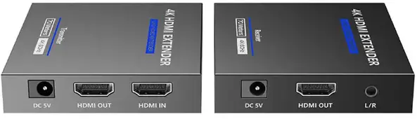
Important Safety Instructions
- To prevent electric shock, please ensure that all apparatus is properly grounded.
- Do not place this device near or over a radiator or heat register, or where it is exposed to direct sunlight.
- Place the device in a well-ventilated area, do not block any ventilation openings.
- Do not expose this device to rain or place it near water. Any liquid that goes into the device may cause a failure, re, or electric shock.
- Do not place the device on an uneven or unstable surface. The device may fall resulting in a malfunction.
- Never insert anything metallic into the open parts of this Device. This may cause a danger of electric shock.
- If a three-party power supply is used, please ensure that the power supply specications meet the product requirements.
Introduction
This is an HDMI point-to-point extender kit, it has zero-latency transmission. The 4K@60Hz HDMI signal can be extended by 230ft (70m)vccccc through CAT6/6A/7 network cable. It supports HDMI loop out, IR passthrough, 3.5mm audio output, etc. This kit is a reliable, ultra-high-denition video transmission solution, which is widely used in security monitoring, home theater, broadcasting, training and other fields.
Features
- Zero-latency transmission.
- Extend 4K@60Hz HDMI signal up to 70m/230ft over Cat6/6A/7 cable.
- The receiver supports 3.5mm stereo output.
- Support HDR10.
- Support EDID passthrough and auto downscaling.
- The transmitter supports HDMI loop out.
- Support IR passthrough.
- Lightning protection, surge protection, ESD protection
Package Contents
- Transmitter x 1

- Receiver x 1
- DC5V/ 1A x 2

- User manual x1

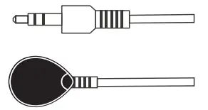
- IR receiver extension cable x 1

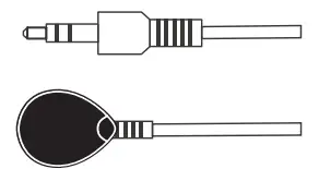
- IR b laster extension cable x 1
- Mounting ear x4

- Screw x10


Installation Requirements
| Item | Item Description | Requirement |
| Signal source | Devices w ith H DM I p ort (PC, D VD, N VR, e tc.) | HDM I c able ≤ 5m |
| Cable | CAT6/ 6A/ 7,following standard I EEE- 568B | CAT6/ 6A/ 7≤ 70m |
| Display device | TVs, p rojectors, etc. with HDM I p ort | HDM I c able ≤ 5 |
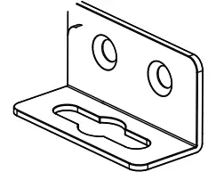
Wall Mounting
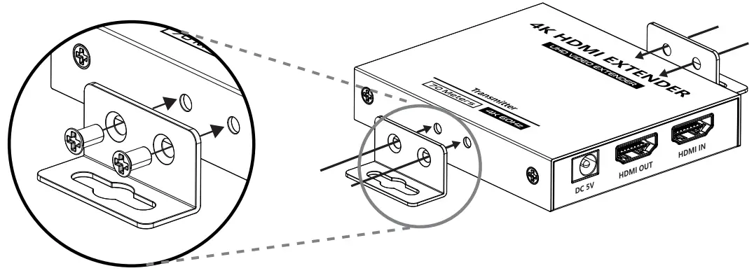
Install the mounting ears on the unit according to the diagram, and select the wall mounting position to x it.
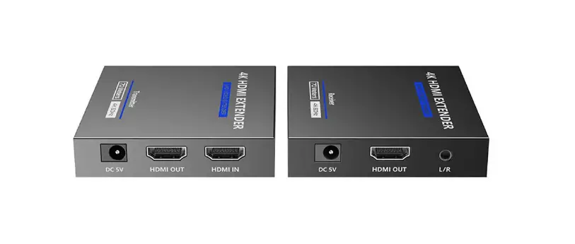
Panel Description
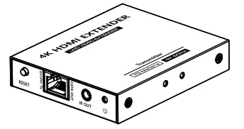
Transmitter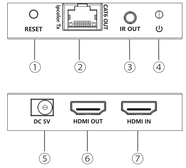
| 1 | Reset button | Pres store start the device |
| 2 | RJ45 output | ConnectwithCAT6/6A/7networkcable |
| 33 | IR out | Connectwith IR b laster extension cable |
| 4 | Power indicator | WhenthereispowerandnoH DMlsignal,theindicatorwillflash,whenthereisH DMI signal,the idicator will light solid |
| 4 | DC5V | Connect with D C5 V/lA poweradapter |
| 5 | HD11/11 output | Connect with local HDMI display device with HDMI cable |
| 6 | HDMI input | Connect with HDMI sourced evicew ithHDM lc able |
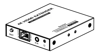
Receiver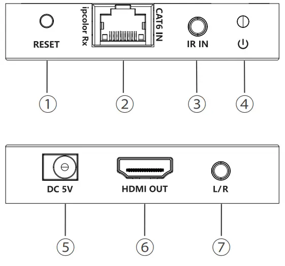
| 1 | Reset b utton | Press to restart the device |
| 2 | R J45 input | Connect w ith C AT6/ 6A/ 7 n etwork c able |
| 3 | IR i n | Connect w ith I R r eceiver e xtension c able |
| 4 | Power i ndicator | W hen t here i s p ower a nd n o H DM I s ignal, the indicator w ill flash, w hen t here i s H DM I signal, the indicator w ill light solid |
| 5 | DC5V | Connect with D C 5 V/ 1A power a dapte |
| 6 | HDM I output | Connect with H DM I display device with HDM I c able |
| 7 | 3.5mm stereo output | Connect with earphone o r speaker |
Installation Procedures
Connection Diagrams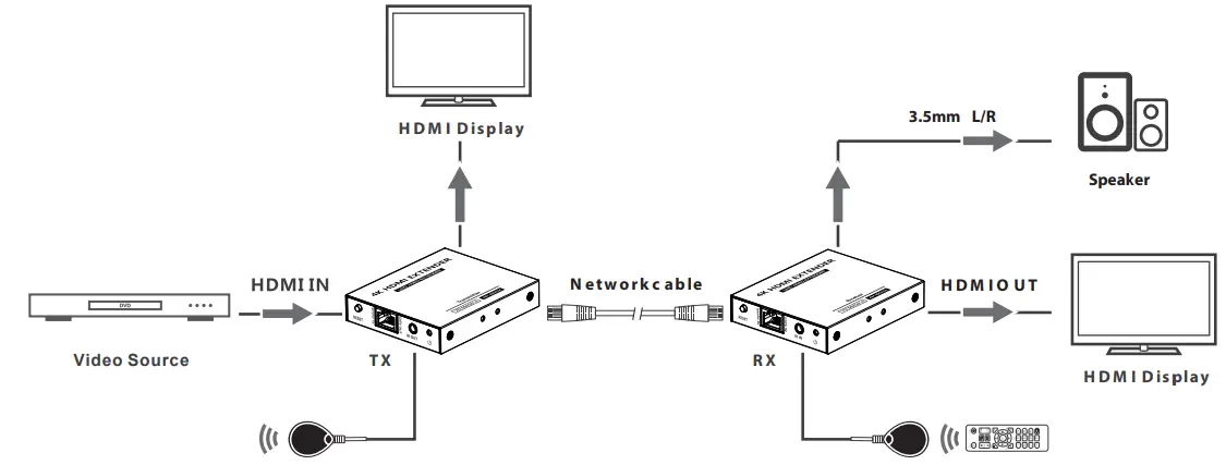
Connection Instructions
- Connect the source device to the HDMI IN port of the transmitter with an HDMI cable, and connect the HDMI OUT port of the receiver to the display device with another HDMI cable.
- Use a Cat6/6A/7 cable to connect the RJ45 port of the transmitter and receiver.
- If using HDMI loop out, connect the display device to the HDMI OUT port of the transmitter.
- If using IR passthrough, the IR blaster extension cable should plug into IR OUT port of the transmitter, the IR receiver extension cable should plug into IR IN port of the receiver.
- If you need to output audio , connect the speaker to the L/R port with a 3.5mm stereo audio cable.
- Plug the power supply into the devices to get started.
Installation Procedures
IR User Guide
IR b laster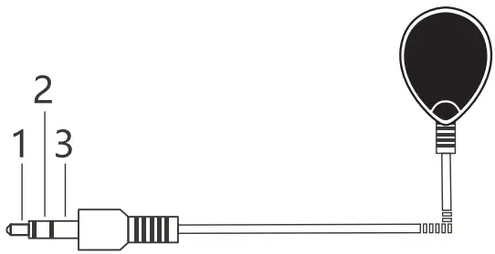
- Power
- IR Sig na l
- Null
IR r eceiver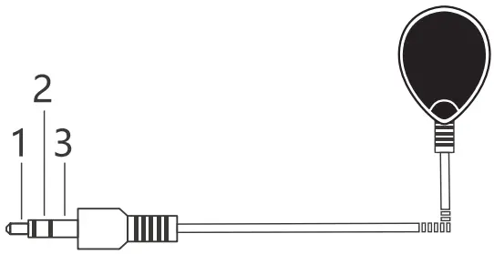
- IR blaster extension cable should plug in the IR OUT port of the transmitter or receiver, IR receiver extension cable should plug in the IR IN port of the transmitter or receiver.
- The emitter of the IR blaster extension cable should be as close as possible to the IR receiving window of the source device.
- Point the remote control at the receiving head of the IR receiver extension cable to operate.
FAQ
Q: The devices are connected correctly, but why is there no image displayed?
A: 1) Please make sure the HDMI cable meets the transmission requirements. (e.g. 4K HDMI cable) 2) Please check and make sure the network cable is connected well. 3) Restart the transmitter or receiver by pressing the reset button.
Q: Why does the display occasionally have a black screen??
A: 1) Check if the length of the cable is within the specied range. 2) Reset the transmitter or receiver to re-built the connection.
Q: Why is the display color abnormal or no sound?
A: 1) Reset the transmitter or receiver to re-built the connection. 2) Check if the HDMI cables are connected well. 3) Reconnect the network cable.
Technical Parameters
| Items | Transmitter | Receiver |
| V ideo | ||
| Inputinter f ac e | 1 x H D M I Ty p e A F e m a le | 1 x R J4 5 F e m a le |
| Outputinterface | 1 x H D M I Ty p e A F e m a le 1 x R J4 5 F e m a le | 1 x H D M I Ty p e A F e m a le |
| H D M I L eng th | ≤5 m | ≤5 m |
| M ax im u mtransf er r ate | 1 8 G b p s | |
| M ax im u mtransm issio n band w id th | 6 0 0 M H z | |
| ED ID p assthro u g h | Ye s | |
| C o m patib ility | H D M I 2 . 0(D e e p c o lo r, 4 K , H D R , Y U V 4 : 4 : 4) | |
| H D C P 2 . 2 | ||
R eso lu t io ns | 4 8 0 i@ 6 0 H z、4 8 0 p @ 6 0 H z、5 7 6 i@ 5 0 H z、5 7 6 p @ 5 0 H z、7 2 0 p @ 5 0 / 6 0 H z、1 0 8 0 i@ 5 0 / 6 0 H z、1 0 8 0 p @ 5 0 / 6 0 H z、3 8 4 0 x 2 1 6 0 @ 2 4 / 2 5 / 3 0 / 5 0 / 6 0 H z、4 0 9 6 x 2 1 6 0 @ 2 4 / 2 5 H z、1 2 8 0 x 9 6 0、1 2 8 0 x 8 0 0、1 2 8 0 x 7 6 8、1 6 8 0 x 1 0 5 0、1 3 6 0 x 7 6 8、1 3 6 6 x 7 6 8、1 6 0 0 x 9 0 0、1 0 2 4 x 7 6 8、8 0 0 x 6 0 0 | |
| Transm issio n d istanc e | C AT 6 / 6 A / 7≤7 0 m | |
| A u d io | ||
| Inp u t i nter f ac e | 1 x H D M I Ty p e A F e m a le | N / A |
| O u tp u t i nter f ac e | 1 x H D M I Ty p e A F e m a le | 1 x H D M I Ty p e A F e m a le 1 x 3 . 5 m m L / R F e m a le |
| A u d io f o rm ats | LP C M / DT S – H D / DT S – A ud io / D o lb y D ig i ta l 5 . 1 C H / D o lb y A tm o s | |
| C o m m and S ig nal | ||
| IR i nter f ac e | 1 x 3 . 5 m m I R O U T F e m a le | 1 x 3 . 5 m m I R I N F e m a le |
| R ec eiving r ang e | ≤5 m | |
| Infrared frequency | 2 0 K H z ~ 6 0 K H z | |
Technical Parameters
| Power | |||
| Power Supply | D C 5 V / 1 A | D C 5 V / 1 A | |
| Power Consumption | <3 W | <3 W | |
| O p erating E nviro nm ent | |||
| W o rkingtem p eratu re | – 2 0°~ | 6 0° | |
| Sto rag etem p eratu re | – 3 0°~ | 7 0° | |
| H u m id ity | 0 ~ 9 0 % R H(N o c o nd e ns a t io n) | ||
| Physical Properties | |||
| Housing | M e ta l | ||
| Weight | 1 4 0 g | 1 4 0 g | |
| Color | B la ck | ||
| Dimensions | 8 5 . 0 ( L)* 7 5 . 5 ( W ) * 1 6 . 5 ( H ) m m | ||
Protection | ES D p ro te ctio n1 a C o nta ct d is cha rg e l e ve l 2 (±4 K V ) 1 b A i r d is cha rg e l e ve l 3 (±8 K V )Im p le m e nta t io n o f t he s ta nd a rd : I EC 6 1 0 0 0 – 4 – 2 | ||
| Lig htning protection, Surge protection | |||
| Certif cations | FCC / C E/ R o H S 2 . 0 | ||


