![]() Equipment and Products for Quality Hay
Equipment and Products for Quality Hay
OWNER’S MANUAL
Model 676
For John Deere 7000 Series
TOOLS NEEDED
- Standard wrench set
- Standard socket set
- Standard screwdriver or 5/16” nut driver
- Side cutter
- Hose cutter
- Crescent wrench
- Hammer
- Metal drilling and cutting tools
INSTALLATION INSTRUCTIONS FOR JOHN DEERE 7000 SERIES
INSTALLATION OF THE TANK AND FRAME
Warning: This tank and frame will only fit John Deere 7000 series Self-Propelled Forage Harvesters.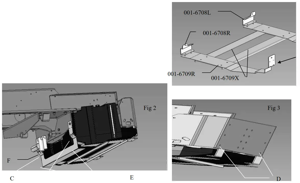
- Begin by laying out components on the ground. Part 001-6709x should be positioned so the flanges are on the bottom side. Place parts 001-6709R and 001-6709L on top of 001-6709X as shown in Figure 1. The 12mm studs extending from the bottom of the brackets will go through the 001-6709X bracket. Use four 12mm serrated flange nuts, from the parts bag, to loosely fasten the parts together.
- Position parts 001-6708R and 001-6708L over parts 001-6709R and 001-6709L as indicated in Figure 1. Fasten the parts together loosely using the 10mm X 100mm bolts and hardware in the parts bag.
- Position the tank on top of the brackets with the fill spout to the left side of the machine.
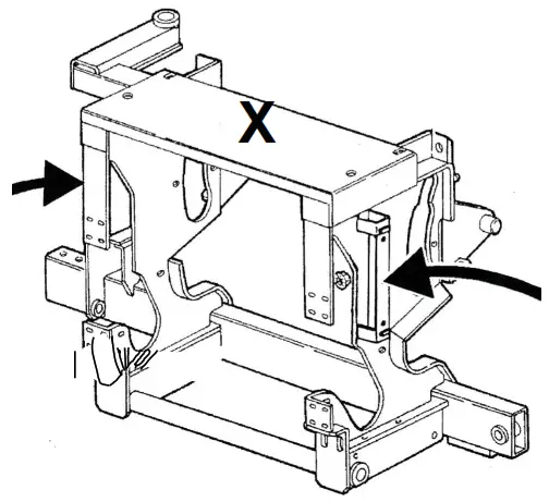
- To prepare the harvester for tank installation, remove the outside bolt and nut from each side of the front mounting plate in Figure 2 (letter C).
- Tank installation: Remove the hitch plate from where it is mounted to the bottom of the frame.
If the machine is used to pull wagons, a weight carrier must be purchased through your John Deere dealer. This weight carrier may also be required to correctly ballast the machine. (See weight distribution chart, page 5.)
a. If there is a suitcase weight bracket attached to the rear of the harvester remove the bottom bolt on each side. (letter D, figure 3) - Mounting the tank and frame to the harvester will require three people, two to lift the tank and one to mount the frame.
- Begin by raising the tank and frame so 001-6708R and 001-6708L are on the inside of the rear bumper. Insert the 12 mm bolts, lock washers, and flat washers through the back of the bumper and thread them into the weld nuts on 001-6708L and 001-6708R. DO NOT FULLY TIGHTEN YET.
- Raise the front on the mounting bracket so it is on the front side of the plate (C in figure 2). Install the official hardware to fasten the front of the mounting brackets.
- Center the tank to the machine and push it forward.
- Tighten the 12mm bolts extending through the rear to 87ft. lbs.
- Retighten the existing hardware on the front side plate.
- Begin tightening the 10mm bolts connecting 001-6708L to 001-6709L and 001-6708R to 0016709R switching from side to side until the tank is secure. Once all of the bolts are tight, cut off the excess thread on the 10mmX100mm bolt with a hacksaw.
- The stalk protector will be mounted on the front side of the tank (using 10mmX30mm bolts and hardware) shown in figure 2 reference E.
PUMP MOUNTING
The pump will be mounted as shown in Figure 2 reference number F. Mount the pump with the provided bolts, locks, and nuts.
MOUNTING OF THE GAUGE
The gauge must be mounted in a location easily visible to the operator from the cab. The gauge should also not interfere with any pertinent visibility requirements for the operator.
PLUMBING
Thread fitting (003-EL3812) into the sump of the tank. From the tank the hose will run to the filter bowl side of the pump, followed by running to the gauge, and from the gauge to the main tee fitting shown on the bottom of page 7. Secure all connections with hose clamps. Make sure to keep the hose away from hydraulic lines, out of the way of moving parts, and away from doors or shields that may need to be moved. DO NOT RUN THE HOSE BETWEEN THE TANK MOUNTING FRAME AND THE TANK.
| SPFH Type | 7200 | 7300/7400/7500 | 7700 | 7800 | ||||||||||
| weight position | outside | outside | outside | outside | ||||||||||
| Header Type | Weight header kg | 40 kg Suitcase weights | 45 kg Suitcase weights | 40 kg Suitcase weights | 45 kg Suitcase weights | 50 kg Suitcase weights | 40 kg Suitcase weights | 45 kg Suitcase weights | 50 kg Suitcase weights | 40 kg Suitcase weights | 45 kg Suitcase weights | 50 kg Suitcase weights | Rear axle | |
| 630 | 1060 kg | 8 | 6 | 0 | 0 | 0 | 0 | 0 | 0 | 0 | 0 | 0 | standard | |
| 4 | 4 | 0 | 0 | 0 | 0 | 0 | 0 | 0 | 0 | 0 | powered | |||
| 640 | 1150 kg | 8 | 8 | 0 | 0 | 0 | 0 | 0 | 0 | 0 | 0 | 0 | standard | |
| 4 | 4 | 0 | 0 | 0 | 0 | 0 | 0 | 0 | 0 | 0 | powered | |||
| 645 | 1275 kg | 12 | 10 | 2 | 2 | 2 | 2 | 2 | 2 | 0 | 0 | 0 | standard | |
| 8 | 6 | 0 | 0 | 0 | 0 | 0 | 0 | 0 | 0 | 0 | powered | |||
| 684 | 1470 kg | 14 | 12 | 8 | 8 | 6 | 10 | 8 | 8 | 4 | 4 | 2 | standard | |
| 12 | 10 | 6 | 6 | 4 | 6 | 6 | 4 | 0 | 0 | 0 | powered | |||
| 676 | 1940 kg | 22 | 20 | 16 | 14 | 14 | 18 | 16 | 14 | 12 | 10 | 10 | standard | |
| 20 | 18 | 14 | 12 | 10 | 16 | 14 | 12 | 10 | 8 | 6 | powered | |||
| 686 | 2260 kg | 24 | 22 | 20 | 18 | 16 | 22 | 20 | 18 | 16 | 14 | 12 | standard | |
| 22 | 20 | 16 | 14 | 14 | 18 | 16 | 14 | 12 | 10 | 10 | powered | |||
| 688 | 2725 kg | not compatible | – | – | 26 | – | – | 28 | – | – | 24 | standard | ||
| not compatible | – | 24 | 22 | – | – | 26 | 24 | 22 | 20 | powered | ||||
| 710 | 3375 kg | not compatible | – | – | – | – | – | – | – | – | 28 | standard | ||
| not compatible | – | – | 28 | – | – | 28 | – | – | 28 | powered | ||||
| 664 | 1130 kg | 10 | 8 | 2 | 2 | 2 | 0 | 0 | 0 | 0 | 0 | 0 | standard | |
| 8 | 6 | 0 | 0 | 0 | 0 | 0 | 0 | 0 | 0 | 0 | powered | |||
| 666R | 1520 kg | 16 | 14 | 10 | 10 | 8 | 12 | 12 | 10 | 6 | 6 | 4 | standard | |
| 14 | 12 | 10 | 8 | 8 | 8 | 8 | 8 | 2 | 2 | 2 | powered | |||
WEIGHT DISTRIBUTION CHART
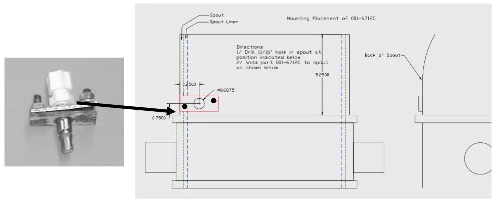
MOUNTING THE SPOUT NOZZLE ASSEMBLY
- The spout nozzle will mount on the back of the spout.
- First, locate and mark the location of the hole where the nozzle will fit into the spout.
- Drill the hole for the spout nozzle, which should be 11/16” in diameter. The material lining in the spout is extremely difficult to drill through so be sure to have a sharp bit.
- Once the spout nozzle hole is drilled, place the assembly on the spout and weld the plate with the treaded studs to the spout. Only the two outer edges need to be welded to the spout.
- Be sure to remove excess slag on the welded plate so that the nozzle plate fits securely.
- The plate containing the nozzle will fit on top of the plate welded to the spout. Fasten the nozzle plate using lock washers and 5/16” nuts. Before fastening, be sure that the nozzle is inserted in the spout so it sprays upward and to the right at approximately a 45-degree angle.
FEED ROLL NOZZLE
- Drill a 9/16” hole in the center of the feed roll frame just behind the top feed roll and just in front of the radial arc feed roll. Make sure that it is out of the way for the movements of both feed rolls.
- Thread nozzle body (004-4722) through the hole and into Jaco’s elbow (003-JEL1414F).
- Place screen (004-1203-100) into the nozzle, followed by tip and cap (004-4723)
- Connect ¼” hose with Jaco nut (003-JN14) 5. Run hose up to check valve assembly
INSTALLATION OF THE LOWER CHUTE –CHUTE LUBE BAR
Gumming from crops can be reduced by spraying water from under the crop in the chute between the cutter head and the accelerator. The chute lube bar mounts in the grass transition chute 2” behind the spiral floor edge. Six holes will need to be drilled in the chute, four 9/16” holes for the spray nozzles and two 3/8” holes for bolting the spray bar in place. Place the spray bar on the chute and mark the location for the 9/16” and 3/8” holes. Use the enclosed 5/16” x 2-inch black Allen head bolts to hold the spray bar in place. Make sure the bolts are inserted from inside the chute to minimize build-up. Note: Washers (not included) may need to be used on the bolts in between the spray bar and chute so the tips of the spray nozzles are flush with the inside of the chute. Run ½” hose from the elbow on the bar to discharge of tee assembly shown below.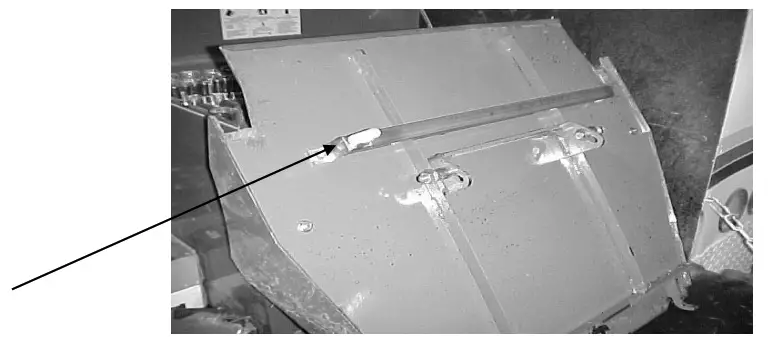
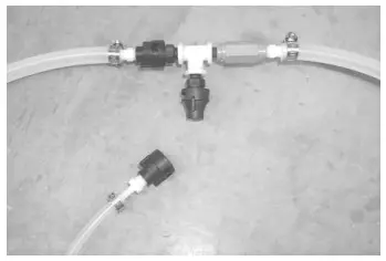
CONNECTING THE SPOUT, FEED ROLL, AND CHUTE NOZZLE PLUMBING
- The enclosed tee assembly should be placed in the line after the pressure gauge.
- To run the chute lubricator only, keep the enclosed cap on the tee.
- To run the spout nozzle only, replace the quick connect that goes to the spout with the quick connect that goes to the chute.
- To run the feed roll sprayer only, keep the enclosed cap on the tee.
- To run two nozzles at a time, place both quick connections going to the nozzles on the tee.
Note only two can be used at a time.
WIRING OF CONTROLS
- The self-propelled forage harvester should have order code 6024 or you will need to order
- Bundle B713547
- Locate power cord (006-4580) in sprayers install kit box 030-6707 and plug it into the back of the control.
- Locate the harness (AZ100126) that came with the Forage Harvester. It has a green wire (065), black wire (310), and red wire (122)
- Connect green wires together with the connectors provided and slide shrink tubing over the connection.
- Connect black wires together with the connectors provided and slide shrink tubing over the connection.
- Heat shrink tubing with a hot air gun or hair dryer. Be careful not to melt wires or coating.
- The red wire is not used. Terminate it so it doesn’t spark. This wire will supply 12 VDC all the time.
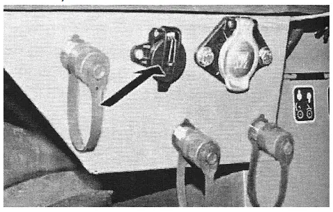
- Plug the harness (AZ100126) into the socket located underneath the headlights on the right fender.
OPERATING INSTRUCTIONS
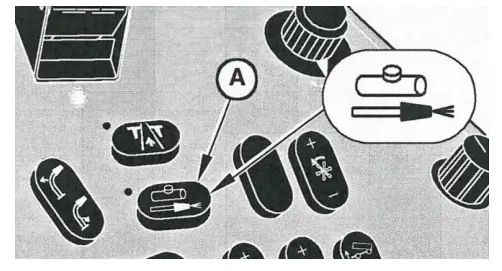
- To operate the unit using the machine’s input, press the Liquid Injection Pump Switch ONCE.
(Located on right-hand arm rest control panel) All of the following have to be present before the power is supplied to the sprayer.
– The road safety switch is in field operating mode
– The forage harvester is traveling forward
– The ground speed is greater than 1.25 mph
– The feed rolls are turning in the forward direction - To allow the sprayer to run all of the time, press the Liquid Injection Pump Switch TWICE
Note: When the Liquid Injection Pump Switch is in standby mode, the tank indicator icon on the corner post will flash. When the pump is running the icon will display solid. Also, there is a light next to the switch that will light up when the switch is activated. - To increase pressure, turn the dial on the sprayer’s control box to the right. To decrease pressure, turn the dial to the left.
For more information refer to the 7000 Series Operators Manual on pages (15-13, 20-64,110-7)
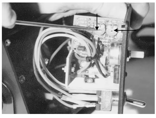
BOX ADJUSTMENT
Electronic units control application rates by regulating pump speed. The control box is factory set, but from time to time may require readjustment. First TURN OFF POWER. Second, remove the control box cover. Lastly, turn the power back on and make the following adjustments:
- MAXIMUM OUTPUT: Can be adjusted with the right-hand adjusting dial. The clockwise adjustment will increase output. With the speed dial turned up do not exceed 90 PSI during operation.

- MINIMUM OUTPUT: Set with a yellow tip in and control all the way down. Adjust with the left-hand adjusting dial. The counter-clock-wise adjustment will decrease output. Set to 12 PSI at the low end. Make adjustments with a small screwdriver. The settings are sensitive and only a small amount of adjustment turn is required.
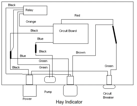
| Relay wiring order: 1: Blue 2: Black 3: Orange 4: Green 5: Not Used | Hay Indicator wiring order: 1: Brown 2: Blue 3: Black 4: White (not used) |
APPLICATION INSTRUCTIONS
Model 676 is compatible with water, bacterial inoculants, enzymes, and organic acid crop preservatives. All of these liquids are similar to water in weight and viscosity, so the charts below will be accurate within 10% for all products used if the system is functioning properly. Always verify the application by checking the product used against desired application per hour.
Look over the chart below and select the spray tip that will provide the desired range of application.
Adjust the pressure with the control box to the setting from the chart below.
GALLONS PER HOUR | |||||
| PRESSURE | |||||
| TIP Number | 20 PSI | 30 PSI | 40 PSI | 50 PSI | 60 PSI |
| 11002 | 8 | 10 | 12 | 14 | 15 |
| 11004 | 17 | 21 | 24 | 27 | 29 |
| 11008 | 34 | 41 | 48 | 53 | 59 |
| 11015 | 63 | 78 | 90 | 100 | 110 |
| 1/8 KSS 1 | 8 | 10 | 12 | 14 | 15 |
| 1/8 KSS 2 | 17 | 21 | 24 | 27 | 29 |
| 1/8 KSS 4 | 34 | 41 | 48 | 53 | 59 |
| JD Chute bar | 29 | 32 | 35 | 38 | NA |
ROUTINE MAINTENANCE
- Clean the tip strainers and main strainer every 10 hours of operation or more frequently if required.
- When inoculants are being used, the system will need to be drained and flushed with water after each use to prevent residue build-up.
- Although the pump can run dry, extended operation of a dry pump will increase wear. Watch the fluid level in the tank.
- Pump performance may start to decline after 400 hours of use. Rebuilding the pump is a simple procedure if the motor is not damaged. Order pump rebuilding kit #007-4581.
WINTER STORAGE
- Thoroughly flush the system with water.
- Remove the filter bowl and run dry until the water has cleared out of the intake side.
- Remove the red plug from the bottom of the pump, drain, and run the pump for 30 seconds or until it is dry.
- Drain all lines on the outlet side.
- Never use oils or alcohol-based anti-freeze in the system.
- For spring start-up, or anytime the pump is frozen, turn off the power immediately to avoid burning the motor out. The pump head can be disassembled and freed or rebuilt in most cases.
TROUBLESHOOTING CHECKS
| PROBLEM | POSSIBLE CAUSE | SOLUTION |
| The pump will not run. | 1. Circuit breaker tripped on electronic unit. | 1. Check for short, low voltage, and reset breakers. |
| 2. Pump locked up. | 2. Clean or rebuild the pump if the motor is OK. | |
| 3. Damaged wire. | 3. Repair damaged wire. | |
| 4. Vapor locked. | 4. Loosen the hose by checking the valve at the gauge and bleed air. | |
| The pump runs but will not prime. | 1. Air leak in intake. | 1. Tighten fittings on the intake side. |
| 2. Clogged intake. | 2. Clean. | |
| 3. Restricted outlet. | 3. Check and clean tips. | |
| 4. Check valve on outlet stuck closed. | 4. Clean or repair check valve. | |
| 5. Dirt inside the pump. | 5. Replace the pump check valve. | |
| The pump does not develop enough output. | 1. Air leaks or clogs on the inlet side. | 1. Tighten or clean filter bowl assembly. |
| 2. Electronic box out of adjustment. | 2. Refer to the box adjustment page. | |
| 3. Pump worn or dirty. | 3. Rebuild the pump. | |
| 4. Low supply voltage. (Pump requires 12v minimum) | 4. Check voltage at connection with a voltmeter. | |
| 5. Bad gauge. | 5. Gauge should read less than 10 PSI when not in use. Also, tips should lose a spray pattern below 10 PSI. Check accuracy. | |
| Pump output varies. | 1. Clogged or restricted inlet. | 1. Clean |
| 2. Worn pump parts. | 2. Rebuild the pump. | |
| 3. Pump not primed. | 3. Prime pump. |
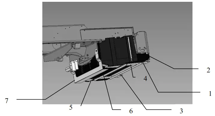
676 PARTS BREAKDOWN FOR SADDLE AND TANK
| Ref | Description | Part # | Qty |
| 1 | TANK | 005-9209 | 1 |
| 2 | LEFT HANGER EXTENSION | 001-6708L | 1 |
| 3 | RIGHT HANGER EXTENSION | 001-6708R | 1 |
| 4 | LEFT TANK HANGER | 001-6709L | 1 |
| 5 | RIGHT TANK HANGER | 001-6709R | 1 |
| 6 | CROSS BRACE | 001-6709X | 1 |
| 7 | STALK PROTECTOR | 001-6709S | 1 |
| NP | TANK BREATHER | 005-9022B2 | 1 |
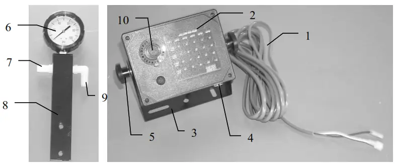
676 PARTS BREAKDOWN OF THE GAUGE AND CONTROL BOX ASSEMBLY
| Ref | Description | Part # | Qty |
| 1 | Control to hitch (8′) | 006-4583 | 1 |
| 2 | Control box complete | 030-0457 | 1 |
| 3 | Control box u-bracket | 001-2012E | 1 |
| 4 | Circuit breaker | 006-2111 | 1 |
| 5 | Control box knobs | 008-0923 | 2 |
| 6 | Gauge | 002-2207Z | 1 |
| 7 | Straight fitting | 003-A1412 | 1 |
| 8 | Gauge holder bracket | 001-6704 | 1 |
| 9 | Elbow fitting | 003-EL1412 | 1 |
| 10 | Speed Dial | 006-2022A | 1 |
| NP | Pump lead (35’) | 006-4575 | 1 |
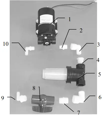
| Ref | Description | Part # | Qty |
| 1 | Pump | 007-4120S | 1 |
| 2 | Nipple fitting | 003-M1238 | 1 |
| 3 | Street elbow fitting | 003-SE12 | 1 |
| 4 | Reducing bushing fitting | 003-RB3412 | 1 |
| 5 | Filter bowl | 002-4318 | 1 |
| 6 | Street elbow fitting | 003-SE34 | 1 |
| 7 | Nipple fitting | 003-M3434 | 1 |
| 8 | Ball valve | 002-2200 | 1 |
| 9 | Elbow fitting | 003-EL3412 | 1 |
PARTS BREAKDOWN FOR 6707 JOHN DEERE 7000 SERIES MOUNTING KIT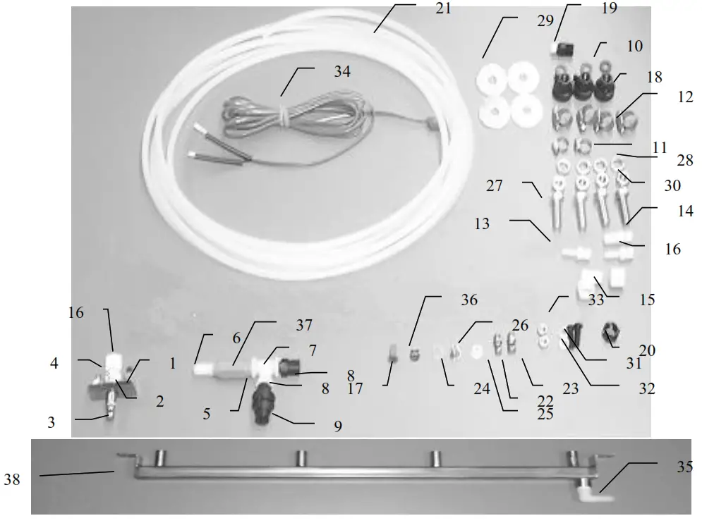
| Ref. | Description | Part # | Qty | Ref. | Description | Part# | Qty |
| 1 | Nozzle holder | 001-6712A | 1 | 20 | Nozzle cap | 004-4723 | 1 |
| 2 | Nozzle base | 001-6712B | 1 | 21 | Tubing-1/4” | 002-9006 | 30 ft |
| 3 | Tip | 004-K2-SS | 1 | 22 | Tip | 004-K1-SS | 1 |
| 4 | Jaco fitting | 003-JA1418 | 1 | 23 | Tip | 004-K4-SS | 1 |
| 5 | Nipple | 003-M14 | 1 | 24 | Tip | 004-XR11002VS | 1 |
| 6 | Straight fitting | 003-A1412 | 2 | 25 | Tip | 004-XR11008VS | 1 |
| 7 | Tee fitting | 003-TT14 | 1 | 26 | Tip | 004-11015-SS | 1 |
| 8 | Quick connect fitting | 004-4710 | 2 | 27 | Bolts | ½”x11/2” | 1 |
| 9 | Cap | 004-1207F | 1 | 28 | Lock washers-1/2” | ||
| 10 | Cap washer | 004-1207W | 1 | 29 | Fender washers-1/2” | ||
| 11 | Hose clamp-#4 | 003-9002 | 2 | 30 | Nuts-1/2” | ||
| 12 | Hose clamp-#6 | 003-9003 | 4 | 31 | 5/16”x1” Black Allen bolts | ||
| 13 | Straight fitting | 003-A1414 | 2 | 32 | Lock washers-5/16” | ||
| 14 | Straight fitting | 003-A1412 | 2 | 33 | Nuts-5/16” | ||
| 15 | Jaco’s elbow | 003-JEL1414F | 1 | 34 | Power cord | 006-4580 | 1 |
| 16 | Jaco nut | 003-JN14 | 2 | 35 | Elbow fitting | 003-EL1412 | 1 |
| 17 | Screen | 004-1203-100 | 1 | 36 | Tip | 004-XR11004VS | 1 |
| 18 | Quick connect fitting | 004-1207H | 3 | 37 | Check valve | 002-4564F | 1 |
| 19 | Nozzle body | 004-4722 | 1 | 38 | Chute lube bar (new style) | 001-6711A | 1 |
NOTES:
Harvest Tec, LLC. Warranty and Liability Agreement.
Harvest Tec, LLC. will repair or replace components that are found to be defective within 12 months from the date of manufacture. Under no circumstances does this warranty cover any components which in the opinion of Harvest Tec, LLC. have been subjected to negligent use, misuse, alteration, accident, or if repairs have been made with parts other than those manufactured and obtainable from Harvest Tec, LLC.
Our obligation under this warranty is limited to repairing or replacing free of charge to the original purchaser any part that in our judgment shows evidence of defective or improper workmanship, provided the part is returned to Harvest Tec, LLC. within 30 days of the failure. Parts must be returned through the selling dealer and distributor, and transportation charges prepaid.
This warranty shall not be interpreted to render Harvest Tec, LLC. liable for injury or damages of any kind, direct, consequential, or contingent, to persons or property. Furthermore, this warranty does not extend to loss of crop, losses caused by delays or any expense prospective profits, or for any other reason. Harvest Tec, LLC. shall not be liable for any recovery greater in amount than the cost or repair of defects in workmanship.
There are no warranties, either expressed or implied, of merchantability or fitness for particular the purpose intended or fitness for any other reason.
This warranty cannot guarantee that existing conditions beyond the control of Harvest Tec, LLC. will not affect our ability to obtain materials or manufacture necessary replacement parts.
Harvest Tec, LLC. reserves the right to make design changes, improve design, or change specifications, at any time without any contingent obligation to purchasers of machines and parts previously sold. Revised 6/22
HARVEST TEC, LLC.
P.O. BOX 63
2821 HARVEY STREET
HUDSON, WI 54016
PHONE: 715-386-9100
1-800-635-7468
FAX: 715-381-1792
Email: [email protected]


