DIGITUS DS-55516 4K HDMI Extender Splitter Set
Important safety notice
- Do not expose this device to rain, moisture and liquid
- Do not put any stuff into the device
- Do not disassemble or repair this device without qualified service technician
- Make sure the specification matched if using 3rd party DC adapters
Introduction
The DIGITUS® HDMI Extender Splitter Set extends an AV signal from the source device over a distance of up to 70 m and distributes it onto 2 screens in UHD resolution (4K/60Hz). Supports CAT 6/7/8 cables. Thanks to PoC, only the transmitter unit needs to be supplied with power by an external power adapter. EDID management, ARC, R232 signal transmission, HDMI loop-out and IR signal transfer are also included as features.
Features
- Supports 4K2K/60Hz (HDR, 4:4:4)
- R232 signal transmission
- Video bandwidth: 18 GBPS
- Maximum transmission distance(UHD 4K2K): 70 m
- POC (Power over Cable) – Only the transmitter unit requires an external power adapter.
- HDMI loop-out to the transmitter unit
- HDCP 2.2 / 1.4
- Supports CAT 6/7/8 cables
- Audio return channel (ARC)
- EDID management
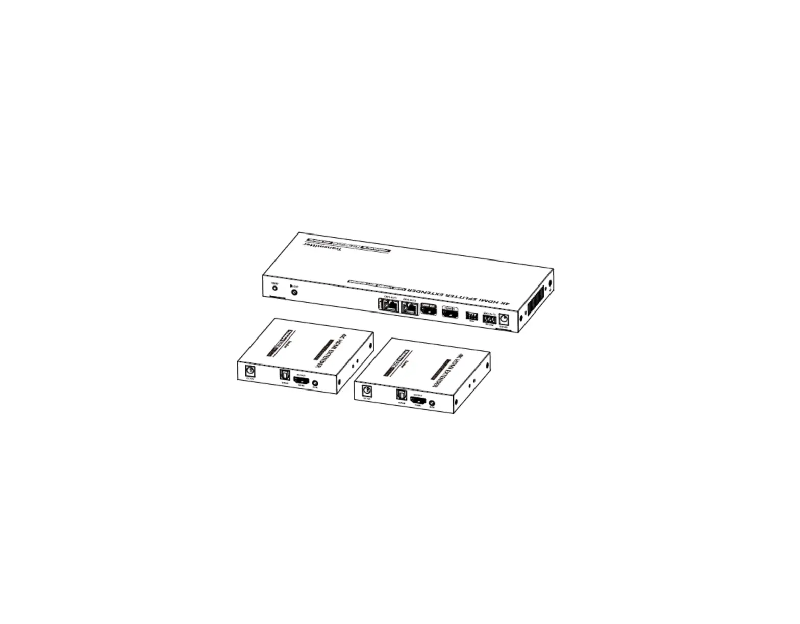
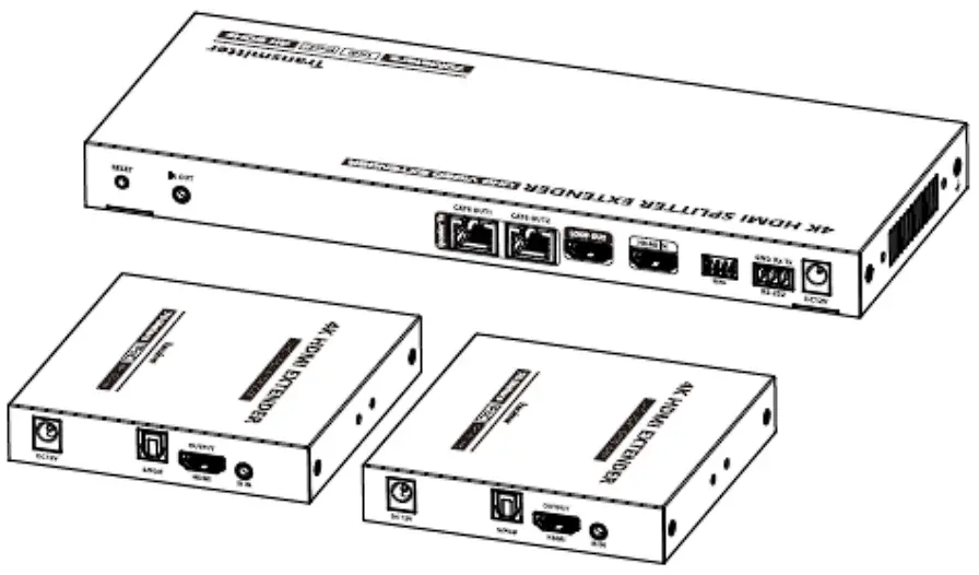
Package Content
- 1x Transmitter unit
- 2x Receiver unit
- 1x IR transmission cable (1.5 m)
- 2x IR receiver cable (1.5 m)
- 1x Power adapter (DC 12V/3A, 1.45 m)
- 1x RS232 terminal block
- 1x Wall mounting fastening material
- 1x User manual
Specification
| Transmission protocol | Ipcolor |
| Distribution mode | 1 IN 2 OUT |
| Transmission distance | CAT6/6A/7≤70m |
| HDMI signal | HDMI 2.0, HDCP 2.2 |
| HDMI Resolution | 480i@60Hz, 480p@60Hz, 576i@50Hz, 576p@50Hz, 720p@50/60Hz, 1080i@50/60Hz,1080p@50/60Hz, 1280×960, 1280×800, 1280×768, 1680×1050, 1360×768, 1366×768, 1600×900,1024×768, 800×600, 3840×2160@24/25/30/50/ |
| Audio formats | LPCM/DTS-HD/DTS-Audio/Dolby Digital 5.1 |
| IR | Support IR pass back function (20KHz~60KHz) |
| RS-232 | 3 pin: TXD-RXD-GND, follows RS-232 levels |
| Working temperature | -20~60°C |
| Storage temperature | -30~70°C |
| Humidity (no condensation) | 0~90% RH |
| Protection | ESD protection 1a Contact discharge level 3 1b Air discharge level 3 Implementation of the standard: IEC61000-4-2 |
| Lightning protection | |
| Surge protection | |
| Power supply | TX: DC12V/3A |
| Power consumption | TX<13W RX<4W |
| Material | Iron |
| Color | Black |
| Weight | TX: 640g RX: 243g |
| Dimension | TX: 264.5(L) x 104.0(W) x 23.0(H)mm RX: 105.5(L) x 102.5(W) x 20.0(H)mm |
Installation Requirements
- HDMI source device (PC, DVD, play station, etc.)
- HDMI display device (TV, monitor, projector, etc.)
- UTP / STP CAT6 / CAT6A / CAT7 cable. Follow standard LEEE-568B It is recommended to choose high-quality network cables
Panel Description
Transmitter (TX)

| 1 | Power indicator | The indicator will turn blue when the power is turned on |
| 2 | Reset button | Restart the device |
| 3 | IR out | Connect with IR blaster extension cable |
| 4 | RJ45 output port | Connect with Cat6/6A/7 network cables |
| 5 | HDMI output port | Connect with local HDMI display device with HDMI cable |
| 6 | HDMI input port | Connect with HDMI source device with HDMI cable |
| 7 | EDID DIP switch | Set output resolution through EDID DIP switch |
| 8 | RS-232 Port | Connect with the external device to control the transmitter. |
| 9 | Power | Connect with DC 12V/3A power adapter |
Receiver (RX)
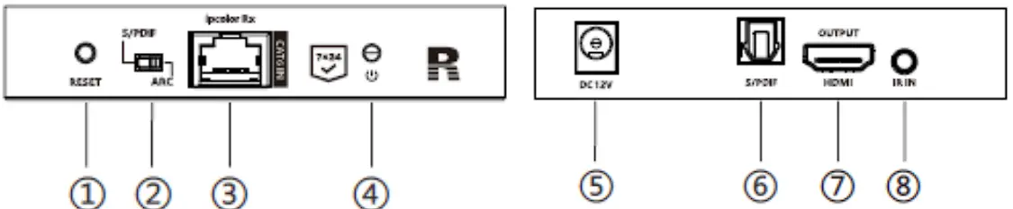
| 1 | Reset button | Restart the device |
| 2 | Audio switch | Choose the audio source (output from the S/PDIF port) S/PDIF: from the source device ARC: from the TV (receiver end) |
| 3 | RJ45 signal input | Connect with Cat6/6A/7 network cables |
| 4 | Power/Signal indicator | When there is power and no HDMI signal, the indicator will flash, when there is HDMI signal, the indicator will light solid blue |
| 5 | Power | Connect with DC12V/2A power adapter |
| 6 | S/PDIF output | Connect with speaker or amplifier |
| 7 | HDMI output | Connect with HDMI display device |
| 8 | IR in | Connect with IR receiver extension cable |
Installation Procedures
Network cable
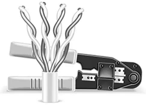
Follow the standard of IEEE-568B:
| 1-Orange/white | 2-Orange | 3-Green/white |
| 4-Blue | 5-Blue/white | 6-Green |
| 7-Brown/white | 8-Brown |
Connection
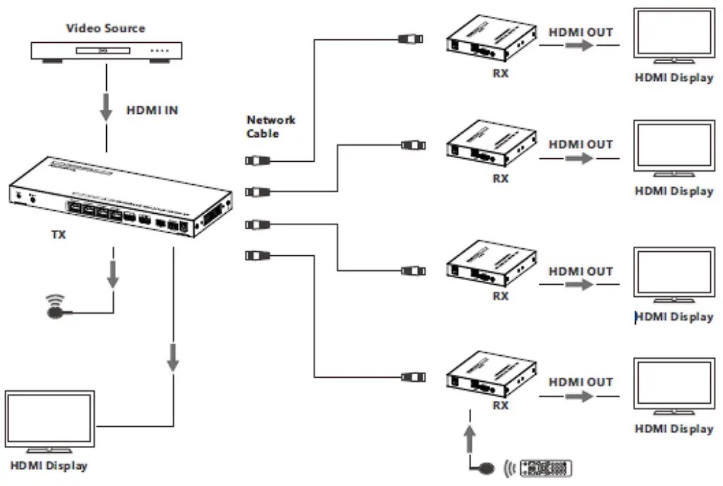
Connection instructions
- Connect the source device to the HDMI IN port of the transmitter through an HDMI cable.
- Connect the CAT6 OUT ports of the transmitter to the CAT6 IN port of the receivers through the network cables.
- Connect the HDMI OUTPUT port of the receivers to the display devices through HDMI cables.
- If using HDMI loop out, connect the LOOP OUT port of the transmitter to the display through an HDMI cable.
- If using the RS-232 control, connect the RS-232 port of the transmitter to an external device.
- Plug the power into the devices to get started.
IR User Guide
- IR blaster extension cable should plug in the IR OUT port of the transmitter, IR receiver extension cable should plug in the IR IN port of the receivers.
- The emitter of the IR blaster extension cable should be as close as possible to the IR receiving window of the source device.
- Point the remote control at the receiving head of the IR receiver extension cable to operate.
Function setting
RS232 settings
The default configuration is as follows:
Baud rate: 9600
Data bits: 8
Stop bits: 1
Parity: 0
| Control Commands | Function Descriptions | |||
| ES XX On【Enter】 | Turn on the network signal output port(s), choose from“01”to“02” (the network ports from left to right are: 01, 02.); “All” means all four ports | |||
| ES XX Off【Enter】 | Turn off the network signal output port(s), choose from “01” to “02” (the network ports from left to right are: 01, 02.); “All” means all four ports | |||
| Reset【Enter】 | Restart the device | |||
| Recover【Enter】 | Restore device factory settings | |||
| Baud XX 【Enter】 | Set the baud rate value: 9600 (default), 19200, 38400, 57600, 115200 | |||
| Examples of control commands are shown below: | ||||
| Control Command | ES 02 On【Enter】 | |||
| Function Description | Turn on network signal output port 02 | |||
| Return Values | Received successfully | ES 02 On OK | ||
| Receive failed | ES 02 On FAIL | |||
| Control Command | ES All Off【Enter】 | |||
| Function Description | Turn off all the network signal output ports | |||
| Return Values | Received successfully | ES All Off OK | ||
| Receive failed | ES All Off FAIL | |||
| Control Command | Reset【Enter】 | |||
| Function Description | Restart the device | |||
| Return Values | Received successfully | Reset OK | ||
| Receive failed | Reset FAIL | |||
| Control Command | Baud 19200【Enter】 | |||
| Function Description | Set the baud rate value: 19200 | |||
| Return Values | Received successfully | Baud 19200 OK | ||
| Receive failed | Baud 19200 FAIL | |||
EDID setting
There are 16 built-in EDIDs in the product, which can be switched through the DIP switch. The upward DIP switch indicates “1”, and the downward DIP switch indicates“0”.
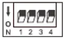 | Switch up for “1” | 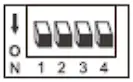 | Switch down for “0” | |||
| Switch Status | EDID Information | |||||
| 1 | 2 | 3 | 4 | |||
| 0 | 0 | 0 | 0 | 4K@60Hz 2CH | ||
| 1 | 0 | 0 | 0 | 4K@60Hz 5.1CH | ||
| 0 | 1 | 0 | 0 | 4K@60Hz 7.1CH | ||
| 0 | 0 | 1 | 0 | 4K@60Hz HDR 7.1CH | ||
| 0 | 0 | 0 | 1 | 4K@30Hz 2CH | ||
| 1 | 1 | 0 | 0 | 4K@30Hz 5.1CH | ||
| 1 | 0 | 1 | 0 | 4K@30Hz 7.1CH | ||
| 1 | 0 | 0 | 1 | 4K@30Hz HDR 7.1CH | ||
| 0 | 1 | 1 | 0 | 1080p@60Hz 2CH | ||
| 0 | 1 | 0 | 1 | 1080p@60Hz 5.1CH | ||
| 0 | 0 | 1 | 1 | 1080p@60Hz 7.1CH | ||
| 1 | 1 | 1 | 0 | 1080i@60Hz 2CH | ||
| 1 | 1 | 0 | 1 | 1080i@60Hz 5.1CH | ||
| 1 | 0 | 1 | 1 | 1080i@60Hz 7.1CH | ||
| 0 | 1 | 1 | 1 | 1080p@60Hz HDR 7.1CH | ||
| 1 | 1 | 1 | 1 | Auto | ||
FAQ
Q: Why there is no image output on the display device?
A: 1) Please check the power supply and all the cables are well-connected.
2) Please check whether there is an HDMI signal input.
3) Please make sure that the corresponding network port output is not turned off by the RS-232 command.
Q: Why is the output image unstable?
A: 1) Please check whether the length of the network cable is within 70 meters.
2) Press the “reset” button on TX and RX panels to restart and reconnect.
Q: Why does the TV have a snowy/fuzzy screen?
A: 1) Please change the HDMI cable or use a shorter HDMI cable.
2) The recommended length of the HDMI cable connected to the transmitter is ≤3 meters, and the recommended length of the HDMI cable connected to the receiver is ≤5 meters.
Disclaimer
The product name and brand name may be registered trademark of related manufactures. ™and® may be omitted on the user manual. The pictures in this user manual are just for reference. The terms HDMI, HDMI High-Definition Multimedia Interface, and the HDMI Logo are trademarks or registered trademarks of HDMI Licensing Administrator, Inc. We reserve the rights to make changes without further notice to a product or system described herein to improve reliability, function or design.
Hereby Assmann Electronic GmbH declares that the Declaration of Conformity is part of the shipping content. If the Declaration of Conformity is missing, you can request it by post under the below mentioned manufacturer address.

www.assmann.com
Assmann Electronic GmbH
Auf dem Schüffel 3 58513 Lüdenscheid Germany