V-TAC 80133970 Magnetic Tracklights-Accessories Instruction Manual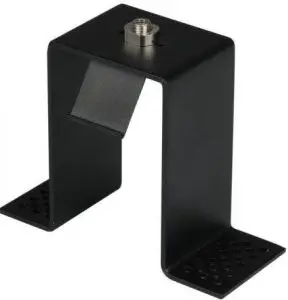
INSTALLATION INSTRUCTION MAGNETIC TRACKLIGHTS – ACCESSORIES
| NO | NAME | SKU | PICTURE | DESCRIPTION |
| 1. | Track connector set (Metal Plate) | 7971 | 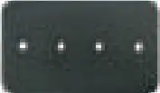 | To be used for track straight line splicing, 1PC for each segment splicing |
| 2. | Track connector set (straight connector) | 7971 | 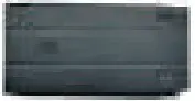 | Option for Conductive Linear Connection of Track |
| 3. | 90’D Connector | 7972 | 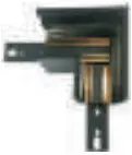 | Surface mounted / Pendant / Recessed (without wings) track horizontal 90° corner splicing |
| 4. | Outer conner connector | 7973 | 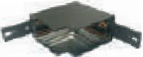 | For vertical track splicing |
| 5. | X connector | 7974 |  | Surface mounted / Pendant / Recessed (without wings) track, + type connector splicing only |
| 6. | T connector | 7975 | 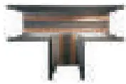 | Only for bright/ lifted/ embedded installation without side rail T type splicing |
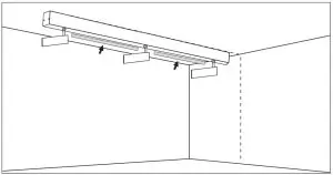
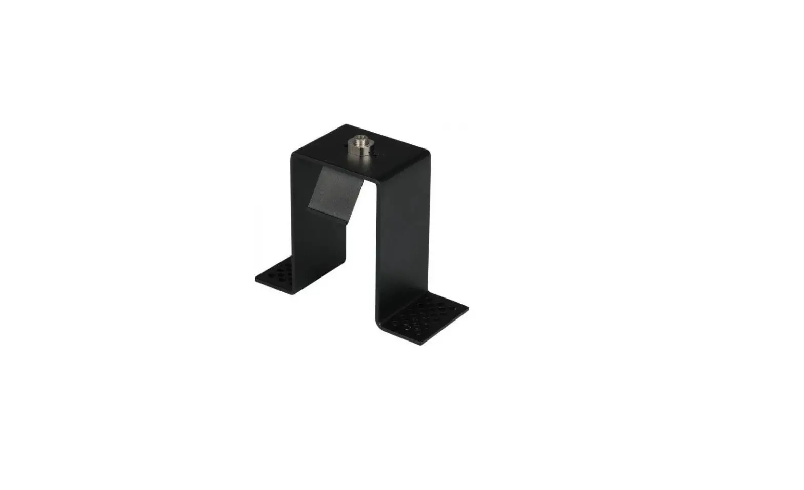
| 7. | Pendant accessory | 7977 | 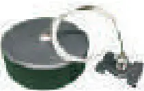 | Used for installation/ marking of track suspension line 1.5m (customizable length of suspension line) |
| 8. | Recessed kit | 7970 | 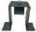 | Installation of recessed (without wings) track only Installation and fixed use |
| 9. | Live end connector | 7979 | 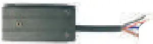 | Conductive use/ optional purchase for connection between track line and power supply |
| 10. | Track cover | 7978 | 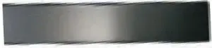 | Magnet track PC Cover for track without lamp |
| 11. | L type track connector | 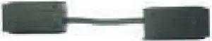 | Conductive use/optional purchase for L type rail connections | |
| 12. | 4x30mm Tapping screw | 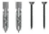 | For track installation and fixed use | |
| 13. | End cap | 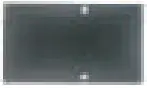 | Used for installation of end caps at both ends of tarck |
IN CASE OF ANY QUERY/ISSUE WITH THE PRODUCT, PLEASE REACH OUT TO US AT: [email protected] FOR MORE PRODUCTS RANGE, INQUIRY PLEASE CONTACT OUR DISTRIBUTOR OR NEAREST DEALERS. V-TAC EUROPE LTD. BULGARIA, PLOVDIV 4000, BUL.L.KARAVELOW 9B
TECHNICAL DATA
| Work voltage | DC24V |
| Maximum current Load | Maximum current 16A per track |
| Load power | 384W (Maximum Load Power) |
| Connect length | The longest track connection 20 m (Max) |
| Product color | Black |
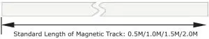
| Splice type | Standard Length of Magnet track Linear connect/Horizontal 90° |
| Standard Length | connect/90° Corner connect/T type connect/+ type connect |
| Protection Level | 0.5M/1 M/1.5M/2M |
| Working temperature | IP20 |
DIMENSION DIAGRAM
Surface mounted/Pendant/ Recessed Track(Without wings)
INTRODUCTION & WARRANTY
 UGR<19 CRI >90
Thank you for selecting and buying V-TAC product. V-TAC will serve you the best. Please read these instructions carefully before starting the installing and keep this manual handy for future reference. If you have any another query, please contact our dealer or local vendor from whom you have purchased the product. They are trained and ready to serve you at the best. The warranty is valid for 3 years from the date of purchase. The warranty does not apply to damage caused by incorrect installation or abnormal wear and tear. The company gives no warranty against damage to any surface due to incorrect removal and installation of the product. The products are suitable for 10-12 Hours Daily operation. Usage of product for 24 Hours a day would void the warranty. This product is warranted for manufacturing defects only.
Application: Office area, Exhibition hall, exclusive store, hotel, villa , club and other related environment.
 This marking indicates that this product should not be disposed of with other household wastes.
 Caution, risk of electric shock.
 MULTI-LANGUAGE MANUAL QR CODE
Please scan the QR code to access the manual in multiple languages.
SAFETY PRECAUTIONS BEFORE INSTALLATION
This product is to be installed in indoor location only. Do not install this lamp on the following locations:
- Temperature below 10°C and above 50°C;
- Ceilings that cannot support the weight of the lamp/lantern; Inclined, concave, or convex ceilings;
- Wet area with the humidity of >80% PH;
- Dusty, has presence of corrosive gases;
- Rooms where magnets are heavily used or altered (operating rooms in hospitals, etc.)
- Near the AC system OR Insulated areas OR Near direct sunlight
Note: Please make sure to turn OFF the power before starting the installation.
WARNING! & SAFETY INSTRUCTIONS
- Please turn off the Power before starting the installation.
- Installation shall only be done by a certified electrician.
- The magnetic suction track needs to be equipped with a 24V DC switching power supply which cannot be directly connected to the municipal electricity.
- Lighting and other power lines (such as AC or high-power electric equipment) should be separated or kept at a distance.
- Before installing/repairing the lamps, make sure that the power supply has been cut off and that the connection is correct before the power supply is switched on [Risk of electric shock].
- Please do not deconstruct or alter the lamp to prevent risk of electric shock, malfunctions, or any kind of accident.
- Do not touch the lamp, when the product is switched on/off, the product is high in temperature.
- Do not install the product with wet hands
- There should be no strong alternating magnetic field around the lamp.
- The built-in magnetic structure of the lamp has great magnetic attraction.
Please be careful when installing the track of the lamp to avoid getting injuries. - The safety buckle should be locked in place when the lamps and lanterns are put on track to avoid risk of falling lamp.
- The actual power of the product ranges from 90% to 110% of the nominal power. The load current carrying capacity of the wires should be considered while wiring.
- The force point of the ceiling in the lighting installation area must be more than four times the weight of the lamp for safety [Risk of falling & failure].
- The lamp can not be used in violation of any fire protection regulation.
- The light source of this luminaire is not replaceable, when the light source reaches its end of life the whole luminaire should be replaced.
- In the presence of smoke & foul odor, please cut off the power immediately and consult the installation personnel/electrician.
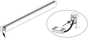
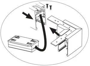
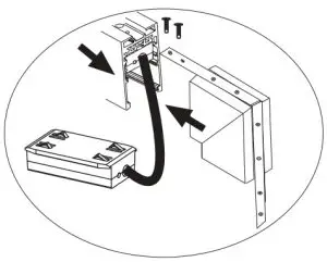
EXTERNAL POWER SUPPLY INSTALLATION
- Remove the end cap from one end of track, insert the power terminal box into the track;
- Put the power supply on the ceiling and wire AC power by brown/blue wire. Take out the DC wire red/blue from the ceiling and insert in the hole of track, then wire with power terminal box.

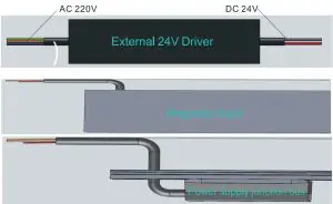
Table 1
| NO | Color | Power wire instructiosn |
| 1 | Brown | AC220V input, connect L wire |
| 2 | Blue | AC220V input, connect wire |
Table 2
| NO. | Color | Function indication of power wire and signal wire installation wiring |
| 1 | Red | Switch power supply output 24V+ |
| 2 | Black | Switch power supply output 24V- |
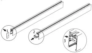
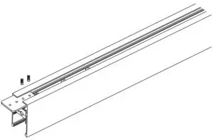
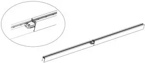
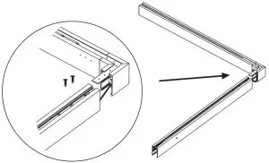
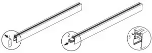
STRAIGHT TRACK CONNECTOR INSTALLATION
Linear track installation using straight track connector
| NO | NAME | SKU | PICTURE | SIZE | DESCRIPTION |
| 1. | Track connector set (Metal Plate) |
7971 | | 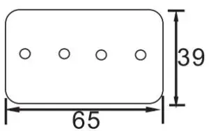 | To be used for track straight line splicing, 1pcs for each segment splicing. |
| 2. | Track connector set (straight connector) | | 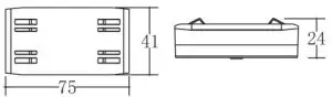 | Use/Option for conductive linear connection of track |
- Remove the end cap from the track rail and connect the straight track connector with the end cap.

- 2. Install straight track connector with fixed metal plates at slot position on the back, and fix screws with inner 6-foot wrench

- Connect the end of another track and fix the inner hexagon screw.

- After connecting the 2 tracks, slide track straight connector to the junction of the 2 tracks for conducting electricity in the middle.

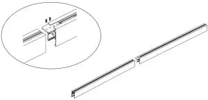
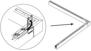
90° CORNER CONNECTOR INSTALLATION
Track installation with Horizontal 90° connector
| NO | NAME | SKU | PICTURE | SIZE | DESCRIPTION |
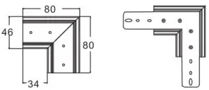
| 1. | 90’D connector | 7972 | |
| Surface mounted / Pendant / Recessed (without wings) track horizontal 90° corner splicing. |
| 2. | L type track connector | Included with SKU:7972 | | 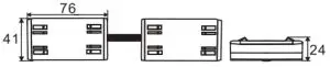 | Use/Option for conductive L type rail connection. |
- Remove the end cap from the track rail and
connect one end of the L type track connector into the track.Remove the end cap
Insert L type corner splicing conductive box into the track - Install the 90° connector on the track.

- Insert the other end of the L type connector into the rail slot to be spliced

- Align the track with the 90° corner connector, fix the track to complete the installation of the connector.

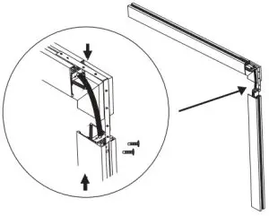
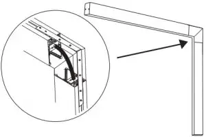
OUTER CORNER CONNECTOR INSTALLATION
Track installation for vertical 90° outer corner installation
- Remove the end cap from the track rail and connect one end of the L type track connector into the track.
Remove the end cap
Insert L type corner splicing conductive box into the track - Install the Outer corner connector on the track

Insert L type corner splicing conductive box into the track and splicing it with a track line
- Insert the other end of the L type Track connector into the track to be spliced
- 4. Align the track with the outer corner connector, fix the track to complete the installation of the connector.

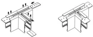
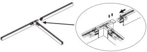
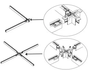
T TYPE CONNECTOR INSTALLATION
Track installation with T Type connector
| NO | NAME | SKU | PICTURE | SIZE | DESCRIPTION |
| 1. | Track connector set (Metal Plate) | 7971 | | 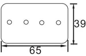 | To be used for track straight line splicing, 1pcs for each segment splicing. |
| 2. | L type track Connector | Included with SKU:7975 | | 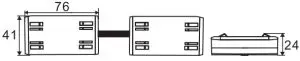 | Use/Option for conductive L type rail connections |
| 3. | Track connector set (straight connector) | Included with SKU:7971 | | 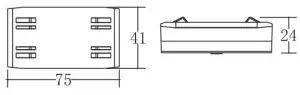 | Use / Option for conductive linear connection of track |
| 4. | T connector | 7975 | | 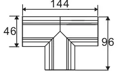 | Surface mounted / Pendant / Recessed (without wings) track, T type connector splicing. |
- Fix 3pcs track connector(metal plate) on the T type track connector as shown in the below image

- Remove the end cap from the track rail and connect one end of the L type track connector into the track
.
Remove the end cap
Insert L type corner splicing conductive box into the track - Insert the other end of the L type track
connector into the second track. Ten the first track and the second track are inserted into the T type connector to form an L type track connector. As show in the diagram below.
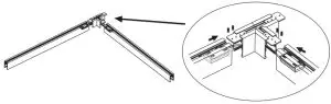
- Installing the third track – Fix one end cap with linear straight track connector

- Insert the third track into the connecting iron plate of the T type connector to complete the T type installation.
- After completing the T shape track installation, slide the straight track connector box to the center of the 2 segment tracks splicing of line connected, so as to provide conducting electricity, and complete the installation. As shown in the below image.
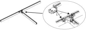
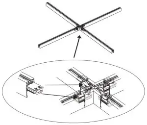
+ TYPE CONNECTOR INSTALLATION
Track installation with “X” Type connector
| NO | NAME | SKU | PICTURE | SIZE | DESCRIPTION |
| 1. | Power and track connector | 7971 | | | To be used for track straight line splicing, 1PC for each segment splicing. |
| 2. | L type track connector | Included with SKU:7974 | | 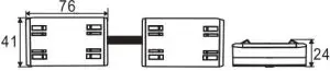 | Use/Option for conductive L type rail connections |
| 3. | X connector | 7974 | | Surface mounted / Pendant / Recessed (without wings) track, X type connector splicing. |
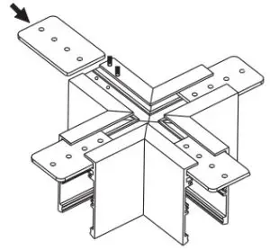
- Fix 4pcs track connector(metal plate) on the X type track connector

- Remove the end cap from the track rail and connect one end of the L type track connector into the first track.
Remove the end cap - Insert L type corner splicing conductive box into the track 3. Insert one end of the “X” connector into the end of first track. Install the L type track connector into the second track and then install the second track to “X” connector to form L shape splicing.

- The 3rd and 4th track rails are to be installed using L type track connector. Refer to step 2 and 3(same installation pattern) in order to complete the installation of “X” connection track. Once the splicing is completed slide the conduction box into the middle of the splicing area(ref image below) so as to provide conducting electricity to the tracks.

PC COVER PLATES ON MAGENTIC SUCTION TRACK INSTALLATION (APPLICABLE FOR ALL TRACK SERIES)
Track installation with PC Cover
| NO | NAME | SKU | PICTURE | SIZE | DESCRIPTION |
| 1. | Track cover | 7978 | | 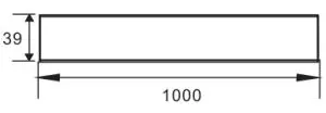 | PC cover is loaded into the empty track to make the track safer and more complete. |
The Installation of magnetic suction track is completed, the track is equipped with magnetic suction lamp, and the track is not equipped with lamp area, which can be fastened by PC cover plate.