MOTOROLA SOLUTIONS WPLN4137 Single Unit Charger User Guide
IMPORTANT SAFETY INSTRUCTIONS
This document contains important safety and operating instructions. Please read these instructions carefully and save them for future reference.
Before using the battery charger, read all the instructions and cautionary markings on (1) the charger, (2) the battery, and (3) on the radio using the battery.
- To reduce risk of injury, charge only the rechargeable Motorola Solutions authorized batteries listed in Table 1. Other batteries may explode, causing personal injury and damage.
- Use of accessories not recommended by Motorola Solutions may result in risk of fire, electric shock, or injury.
- To reduce risk of damage to the electric plug and cord, pull by the plug rather than the cord when disconnecting the charger.
- An extension cord should not be used unless absolutely necessary. Use of an improper extension cord could result in risk of fire and electric shock. If an extension cord must be used, make sure that the cord size is 18 AWG for lengths up to 100 feet (30.48 m), and 16 AWG for lengths up to 150 feet (45.72 m).
- To reduce risk of fire, electric shock, or injury, do not operate the charger if it has been broken or damaged in any way.
Take it to a qualified Motorola Solutions service representative. - Do not disassemble the charger; it is not repairable and replacement parts are not available. Disassembly of the charger may result in risk of electrical shock or fire.
- To reduce risk of electric shock, unplug the transformer from the a.c. outlet before attempting any maintenance or cleaning.
- This is a Class A product. In a domestic environment, this product may cause radio interference in which case the user may be required to take adequate measures.
OPERATIONAL SAFETY GUIDELINES
- Turn radio off when charging battery.
- This equipment is not suitable for outdoor use. Use only in dry locations/conditions.
- Connect equipment only to an appropriately fused and wired supply of the correct voltage (as specified on the product).
- Disconnect from line voltage by removing the transformer from the AC outlet.
- The a.c.voutlet to which this equipment is connected should be close by and easily accessible.
- Maximum ambient temperature around the power supply equipment must not exceed 40 °C (104 °F).
- Output power from the power supply unit must not exceed the ratings stated on the product label located on the bottom of the charger.
- Make sure the cord is located where it will not be stepped on, tripped over, or subjected to water, damage, or stress.
CHARGER SPECIFICATION
- Input: 14 V
 , 1 A
, 1 A - Output: 11.2 V , 950 mA
Table 1 Motorola Solutions Authorized Batteries
| Kit (part) Number | Battery Chemistry/Description |
| NNTN4496_R | NiCd Battery, 1100 mAH |
| NNTN4497_R | Li-Ion Battery, 2250 mAH |
| NNTN4851_R | NiMH Battery , 1400 mAH |
| NNTN4852_R | NiMH Battery, 1300 mAH, FM |
| NNTN4970_R | Slim Li-Ion Battery, 1600 mAH |
| PMNN4098_R | NiMH Battery, 1400 mAH |
| PMNN4251_ | NiMH Battery, 1400 mAH, CE-LPS |
| PMNN4252_ | NiMH Battery, 1300 mAH, FM, CE-LPS |
| PMNN4253_ | Slim Li-Ion Battery, 1600 mAH, CE-LPS |
| PMNN4254_ | Li-Ion Battery, 2300 mAH, CE-LPS |
| PMNN4256_ | NiCd Battery, 1050 mAH, CE-LPS |
| PMNN4450_ | Li-Ion Battery, 2800 mAH, 2900T |
| PMNN4458_ | Li-Ion Battery, 2050 mAH, 2075T (MAG ONE) |
Note: In Taiwan, only battery NNTN4497DRW is available.
These Class 2 battery chargers should be used with the direct plug-in, Motorola Solutions authorized transformers listed below:
Table 2 Power Sources/Transformers
| Kit Part Number | Description | Power Supply Part Number |
| WPLN4137_R | Base Charger | N/A |
| WPLN4138_R | Single Unit Desktop Rapid Charger – US/Taiwan | 25009297001 |
| WPLN4139_R | Single Unit Desktop Rapid Charger – Europe | PS000037A01 |
| 2571586S03 (Alternate) | ||
| WPLN4140_R | Single Unit Desktop Rapid Charger – UK | PS000037A02 |
| 2571586S02 (Alternate) | ||
| WPLN4142_R | Single Unit Desktop Rapid Charger – Argentina | PS000037A04 |
| 2571586S09 (Alternate) |
| Kit Part Number | Description | Power Supply Part Number |
| PMLN5189_ | Single Unit Desktop Rapid Charger – Argentina | PS000037A04 |
| 2571886T01 (Alternate) | ||
| PMLN5190_ | Single Unit Desktop Rapid Charger – Aus/Nz | PS000037A03 |
| 2571886T01 (Alternate) | ||
| PMLN5191A | Single Unit Desktop Rapid Charger – UK | PS000037A02 |
| 2571886T01 (Alternate) | ||
| PMLN5191B | Single Unit Desktop Rapid Charger – UK | PS000037A02 |
| 25012006001 (Alternate) | ||
| PMLN5192A | Single Unit Desktop Rapid Charger – Europe | PS000037A01 |
| 2571886T01 (Alternate) | ||
| PMLN5192B | Single Unit Desktop Rapid Charger – Europe | PS000037A02 |
| 25012006001 (Alternate) | ||
| PMLN5193A | Single Unit Desktop Rapid Charger – US | 25009297001 |
| 2571886T01 (Alternate) | ||
| PMLN5193B | Single Unit Desktop Rapid Charger – US | 25009297001 |
| 25012006001 (Alternate) | ||
| PMLN5204_ | Single Unit Desktop Rapid Charger – Korea | PS000037A06 |
| 2571886T01 (Alternate) | ||
| PMLN5206_ | Single Unit Desktop Rapid Charger – China | PS000037A05 |
| 2571886T01 (Alternate) | ||
| WPLN4280_ | Single Unit Desktop Rapid Charger – Brazil | 2571886T01 |
| PMTN4096 | Single Unit Desktop Rapid Charger- China | 2564060M02 |
| PMLN5204 | Single Unit Desktop Rapid Charger – Korea | 2571886T01 |
OPERATING INSTRUCTIONS
Single-unit chargers will charge only the Motorola Solutions authorized batteries listed in Table 1. Other batteries may not charge.
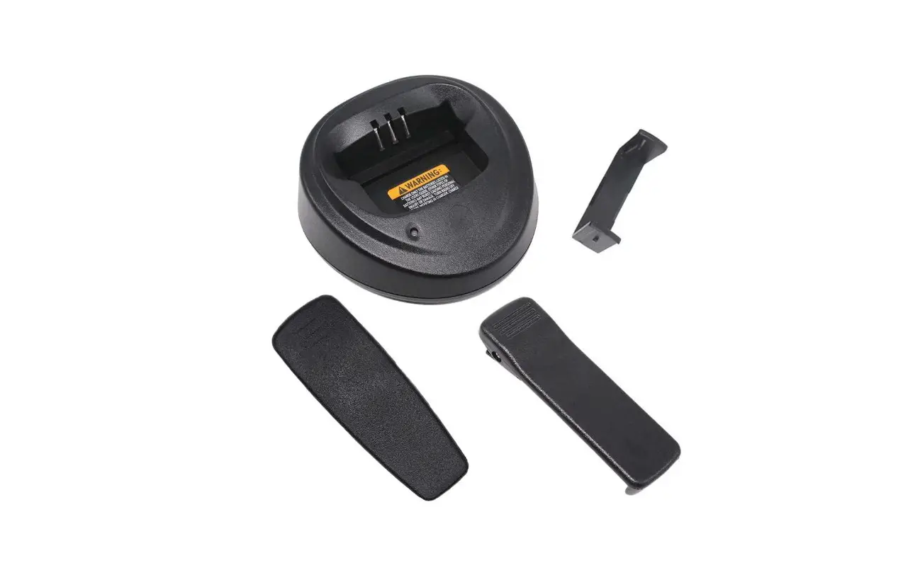
The battery charger’s pocket will accommodate either a radio with a battery attached or a battery alone. Prior to charging a battery with radio, turn the radio off. To charge a battery, use the following procedure: (Refer to Figure 1.)
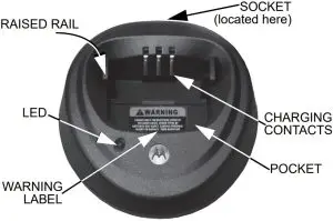
- Plug the round end of the transformer cord into the socket on the back of the charger.
- Plug the transformer into the appropriate AC outlet.
The charger LED will blink green once to indicate asuccessful power-up. - Insert a battery, or a radio with battery (radio turnedoff), into the charger’s pocket by:
- aligning the groove on each side of the battery with the corresponding raised rail on each side of the charger pocket
- pressing the battery toward the rear of the pocket
- sliding the battery into the charger pocket, ensuring complete contact between the charger and battery contacts
- When the battery is properly seated in the pocket, the charger LED will light red to indicate that the battery is charging rapidly. When the battery is 90% charged, the LED will begin to blink green to indicate that the battery is trickle charging. When the battery is fully charged, the LED will change to a steady green light to indicate that the battery is fully charged.
Note: Even though new batteries might prematurely indicate a full charge (steady green LED), charge the battery for 14 to 16 hours prior to initial use for best performance. Batteries will charge best at room temperature.
Figure 1 Battery Charger
Battery Locating Rail Adapter
The battery locating rail is a remove able part which constitutes an adapter to accommodate standard and slimline batteries. (Refer to Figure 2.)

Figure 2 Battery Locating Rail removed
The charger is shipped with the battery locating rail in the standard battery position.
To change to the slimline battery position:
- Remove the battery locating rail by pinching inward both sides while pulling from the charger pocket.
- Turn the battery locating rail around so the back faces the front.
- Re-insert into the charger pocket.
TROUBLESHOOTING
When troubleshooting, always observe the color of the LED:
Table 3 LED Indications of Battery/Charger Status
| LED Color | Battery/Charger Status |
| No LED indication | Battery is inserted incorrectly. |
| Single green blink | Successful charger power-up. |
| Blinking red | Battery is unchargeable or not making proper contact. |
| Steady red | Battery is in rapid-charge mode. |
| Blinking yellow | Battery is in charger, not in rapid-charge mode but waiting to be charged. |
| Blinking green | Battery is charged (to 90% or greater capacity). |
| Steady green | Battery is fully charged. |
No LED Indication?
- Check that the radio with battery, or the battery alone, is inserted correctly (refer to step 3 on page 6).
- Make sure that the transformer is plugged into an appropriate AC outlet, and that the transformer cable is plugged securely into the charger socket.
Blinking Red LED Indicator?
- Remove the battery from the charger, and:
- make sure that it is a Motorola Solutions authorized battery listed in Table 1. Other batteries may not charge.
- remove the battery from the charger and use a pencil eraser to clean the three metal contacts at the back of the battery. Place the battery back in the charger.
- Power up the charger and place the battery back into the charger pocket. If the LED indicator continues to blink red, replace the battery.
Blinking Yellow LED Indicator?
- the battery temperature may be below 5 °C (41 °F) or above 40 °C (104 °F).
- the battery voltage may be lower than the predetermined threshold level for rapid charging.
Note: Rapid charging outside of the stated temperature and voltage limits can drastically reduce the life expectancy of the battery.
Note: When the battery charger detects the proper battery conditions, rapid charging begins automatically (steady red LED).
SERVICE
The Single-Unit Chargers are not repairable. Order replacement chargers as necessary
MOTOROLA, MOTO, MOTOROLA SOLUTIONS and the Stylized M logo are trademarks or registered trademarks of Motorola Trademark Holdings, LLC and are used under license.
All other trademarks are the property of their respective owners.
© 2002 and 2020 by Motorola Solutions, Inc. All rights reserved.


