![]()
![]()
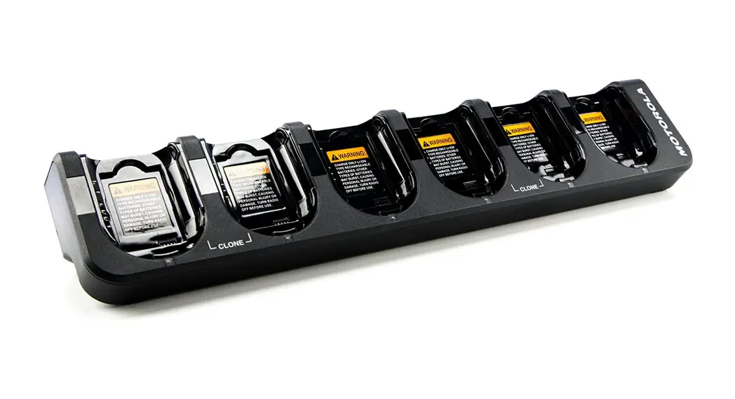
MAINTENANCE MULTI-UNIT CHARGER KITS
PMPN4308/PMPN4309/PMPN4310/
PMPN4311/PMPN4312/PMPN4319/
PMPN4320/PMPN4321/PMPN4322
QUICK START GUIDE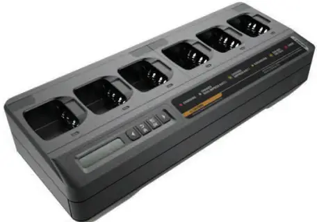
Important Safety Instructions
This document contains important safety and operating instructions. Please read these instructions carefully and save them for future reference. Before using the battery charger, read all the instructions and cautionary markings on (1) the charger and (2) the battery.
- To reduce the risk of damage to the power cords, pull the plug rather than the! cord when disconnecting from the AC outlet or
 the charger.
 - An extension cord should not be used unless absolutely necessary. Use W A R N I N G of an improper extension cord could result in a risk of fire and electric shock. If an extension cord must be used, make sure that the cord size is 18 AWG for lengths of up to 6.5 feet (2.0 m), and 16 AWG for lengths up to 9.8 feet (3.0 m).
- To reduce the risk of fire, electric shock, or injury, do not operate the charger if it has been broken or damaged in any way. Take it to a qualified Motorola Solutions service representative.
- Do not disassemble the charger. It is not repairable and replacement parts are not available. Disassembly of the charger may result in a risk of electric shock or fire.
- To reduce the risk of electric shock, unplug the charger power cord from the AC outlet before attempting any maintenance or cleaning.
- To reduce the risk of injury, charge only the rechargeable Motorola Solutions authorized batteries listed in Table 4. Other batteries may explode, causing personal injury and damage.
- Use of accessories not recommended by Motorola Solutions may result in a risk of fire, electric shock, or injury.
Operational Safety Guidelines
- This equipment is not suitable for outdoor use. Use only in dry locations and conditions.
- Maximum ambient temperature around the charger must not exceed 40 °C (104 °F).
- Connect the charger to the power supply listed in Table 2 with an appropriate power cord listed in Table 3.
- The AC outlet to which the power cord is connected should be closed and easily accessible.
- Make sure the power cord is located where it will not be stepped on, tripped over, or subjected to water, damage, or stress.
- Connect the power cord only to an appropriately fused and wired AC outlet with the correct voltage, as specified on the product.
- Disconnect from line voltage by removing the power cord from the AC outlet.
- The Maintenance Charger charges the batteries listed in Table 4.
Table 1: Multi-Unit Charger
| Kit Number | Kit Description | Base Kit Number | Power Cord |
| PMPN4308 | IMPRES 2, 1-Display Maintenance Multi-Unit Charger, Europe | PMPN4327 | 3087791G04 |
| PMPN4309 | IMPRES 2, 1-Display Maintenance Multi-Unit Charger, Australia/New Zealand | PMPN4327 | 3087791G10 |
| PMPN4310 | IMPRES 2, 1-Display Maintenance Multi-Unit Charger, Korea | PMPN4327 | 3087791G16 |
| PMPN4311 | IMPRES 2, 1-Display Maintenance Multi-Unit Charger, Japan | PMPN4327 | 3087791G20 |
| PMPN4312 | IMPRES 2, 1-Display Maintenance Multi-Unit Charger, China | PMPN4327 | CB000199A01 |
| PMPN4319 | IMPRES 2, 1-Display Maintenance Multi-Unit Charger, United Kingdom/Hong Kong | PMPN4327 | 3087791G07 |
| PMPN4320 | IMPRES 2, 1-Display Maintenance Multi-Unit Charger, Brazil | PMPN4327 | 3087791G22 |
| PMPN4321 | IMPRES 2, 1-Display Maintenance Multi-Unit Charger, US | PMPN4327 | 3087791G01 |
| PMPN4322 | IMPRES 2, 1-Display Maintenance Multi-Unit Charger, Argentina | PMPN4327 | 3087791G13 |
Table 2: Motorola Solutions Authorized Power Supply
| Part Number | Description |
| PS000242A01 | External 90 W Power Supply |
Table 3: Motorola Solutions Authorized Power Cords
| Part Number | Description |
| 3087791G01 | Power Cord, US |
| 3087791G04 | Power Cord, Europe |
| 3087791607 | Power Cord, United Kingdom/Hong Kong |
| 3087791G10 | Power Cord, Australia/New Zealand |
| 3087791G13 | Power Cord, Argentina |
| 3087791G16 | Power Cord, Korea |
| 3087791G20 | Power Cord, Japan |
| 3087791G22 | Power Cord, Brazil |
Table 3: Motorola Solutions Authorized Power Cords (Continued)
| CB000199A01 | Power Cord, China |
Table 4: Motorola Solutions Authorized Batteries
| Charger Kit Number | Battery Kit Number | Description |
| PMPN4327 | NNTN8287— | IMPRES Li-Ion Battery 1750mAh |
| NNTN8386_ | IMPRES CSA157 Li-Ion Battery 2300mAh | |
| NNTN8359_ | IMPRES ATEX Li-Ion Battery 2075mAh | |
| NNTN8570_ | IMPRES ATEX Li-Ion Battery 1250mAh | |
| NNTN8750_ | IMPRES CSA157 Li-Ion Battery 2050mAh | |
| NNTN8840_ | IMPRES ATEX Li-Ion Battery 2000mAh |
Charger Overview
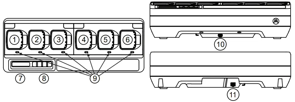 Figure 1: Charger Overview
Table 5: Charger Overview and Description
| Number | Description |
| 1-6 | Charging Pockets — To charge stand-alone batteries. |
| 7 | Display — For Pocket 1 only. Displays the available menu selections. |
| 8 | Keypad — For menu selection. |
| 9 | LED Status Indicator — Indicates the charging status of the battery. |
| 10 | Communications Interface — Supports charger reprogramming. |
| 11 | Power Connector Inlet — Compatible with Power Supply in Table 2. |
Operating Instructions
- Batteries charge best at room temperature.
- DO NOT leave batteries in the charger after charging is complete.
Charging Procedure
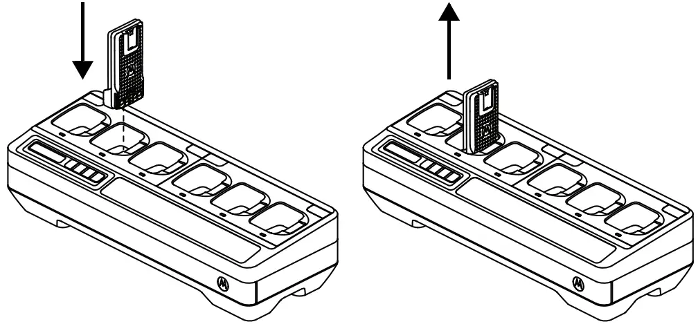 Figure 2: Charging Procedure
- Place the Multi-Unit Charger (MUC) on a flat surface.
- Firmly insert the power supply into the charger DC Inlet Socket at the back of the charger.
- Plug the power supply power cord into a matching power outlet.
- Upon successful power-up, each pocket LED shows Green for one second and
IMPRES 2 MAINTENANCE CHGR is displayed. If the LEDs do not flash and no message is displayed, check power cord connections. - Insert the battery into an available pocket.
- When the battery is properly seated in the pocket:
– Charging status of a battery is indicated by the LED Status Indicator of the associated pocket on the MUC.
– The Display of the MUC shows the charging status of Pocket 1 only. - The battery is ready when LED is Steady Green (for non-IMPRES or non-IMPRES 2
Motorola Solutions battery) or Alternating Amber/Green (for IMPRES or IMPRES 2 Motorola Solutions battery).
Display Messages and Led Indications
Table 6: IMPRES 2™ or IMPRES™ Battery for Long-Term Storage
Status | Charger Display | LED Indicator |
| Charger Powers On | IMPRES 2 MAINTENANCE CHGR | Green for approximately |
| Battery Detected | IMPRES 2 | Battery requires Discharge: Steady Amber Battery requires Charge: Steady Red Battery requires Calibration, but Calibration is disabled by Long-Term Storage: Alternating Amber/ Green |
| Battery Discharging | STORAGE DISCHARGE xx% Rated Cap | Steady Amber |
| Rapid Charging to selection | STORAGE CHARGE | Steady Red |
| Nearly Charged selection | STORE TRKL DIRGE | Flashing Green |
| Complete Ready to Store | LONGTERM STORAGE xx% Rated Cap | Battery does not require Calibration: Steady Green Battery requires Calibration, but Calibration is disabled in charger: Alternating Amber/ Green Battery may be nearing End of Service (battery is usable): Alternating Red/Green |
| Fault • Battery Faulted • No discharge current • Capacity too low to complete charge | Warning: NOT CHARGEABLE REMOVE & REINSERT or CANNOT DISCHARGE FOR LT STORAGE or STORE INCOMPLETE Low Capacity:yy% | Flashing Red |
| Standby • Battery is waiting to rapid charge.• Battery may be too hot, too cold, or low voltage. • Charger may be too hot. | Warning: HOT BATTERY WAITING TO CHRGE or COLD BATTERY WAITING TO CHRGE or VERY LOW BATTERY WAITING TO CHRGE or HOT CHARGER WAITING TO CHRGE | Flashing Amber
|
Table 7: Other Motorola Solutions Batteries for Long-Term Storage
Status | Charger Display | LED Indicator |
| Charger Powers On | IMPRES 2 | Green for approximately 1second |
| Battery Detected • Motorola Solutions battery is not IMPRES 2 or IMPRES • Battery is Unknown | WRONG BATT TYPE | Flashing Red |
| Fault (Battery Faulted) | Warning: | Flashing Red |
| Standby • Battery is waiting to rapidcharge. Battery may be too hot, too cold, or low voltage. | Warning: HOT BATTERY | Flashing Amber |
Table 8: IMPRES 2™ or IMPRES™ Lithium-ion Battery for Shipment
Status | Charger Display | LED Indication |
| Charger Powers On | IMPRES 2 MAINTENANCE CHGR | Green for approximately 1 second |
| Battery Detected | IMPRES 2 | Battery requires Discharge: Steady Amber Battery requires Charge: Steady Red Battery requires Calibration, but Calibration is disabled by Ship Lithium: Alternating Amber/ Green for 4 seconds |
| Battery Discharging | SHIP LI DISCHRGE xx% Rated Cap | Steady Amber |
| Rapid Charging toselection | SHIP LI CHARGE xx% Rated Cap | Steady Red |
| Complete Ready to Ship | LI READY TO SHIP xx% Rated Cap | Battery does not require Calibration: Steady Green Battery requires Calibration, but Calibration is disabled in charger: Alternating Amber/Green Battery may be nearing End of Service (battery is usable): Alternating Red/Green |
| Fault • Battery Faulted • No discharge current • Capacity too low to complete charge | Warning: NOT CHARGEABLE REMOVE& REINSERT or CANNOT DISCHARGE FOR LI SHIPMENT or SHIP INCOMPLETE Low Capacity:yy% | Flashing Red |
| Standby • Battery is waiting torapid charge • Battery may be too hot, too cold, or low voltage • Charger may be too hot | Warning: HOT BATTERY WAITING TO CHRGE or COLD BATTERY WAITING TO CHRGE or VERY LOW BATTERY WAITING TO CHRGE or HOT CHARGER WAITING TO CHRGE | Flashing Amber |
Table 9: Other Motorola Solutions Lithium-ion Batteries for Shipment
| Status | Charger Display | LED Indication |
| Charger Powers On | IMPRES 2 MAINTENANCE CHGR | Green for approximately 1 second |
| Battery Insertion | MOTOROLA SOLUTNS BATTERY | Steady Amber |
| Battery Discharging | SHIP LI DISCHRGE | Steady Amber |
| Rapid Charging | SHIP LI CHARGE xx% Rated Cap | Steady Red |
| Complete Charging Ready to Ship | LI READY TO SHIP xx% Rated Cap | Steady Green |
| Fault • Battery Faulted • Motorola Solutions battery is Nickel • Battery is Unknown | Warning: NOT CHARGEABLE REMOVE& REINSERT or WRONG BATT TYPE CANNOT SHIP LI | Flashing Red |
| Standby • Battery is waiting to rapid charge • Battery may be too hot, too cold, or low voltage • Charger may be too hot | Warning: HOT BATTERY WAITING TO CHRGE or COLD BATTERY WAITING TO CHRGE or VERY LOW BATTERY WAITING TO CHRGE | Flashing Amber |
Optional equipment
A wall mount bracket (Part Number BR000271A01) is available for the Multi-Unit Charger (MUC). Contact your local dealer to order this item. Installation of the wall mount bracket is as follows:
 | • This wall mount bracket should be installed by a trained and experienced technician. Having the product installed by a non-specialized technician is very dangerous, and can cause damage or injury. • Do not install the product where the weight cannot be supported. If the strength of the location where the wall mount is installed is not strong enough, it can fall off and cause an injury. • Do not install on a structure that is prone to vibration, movement, or chance of impact. |
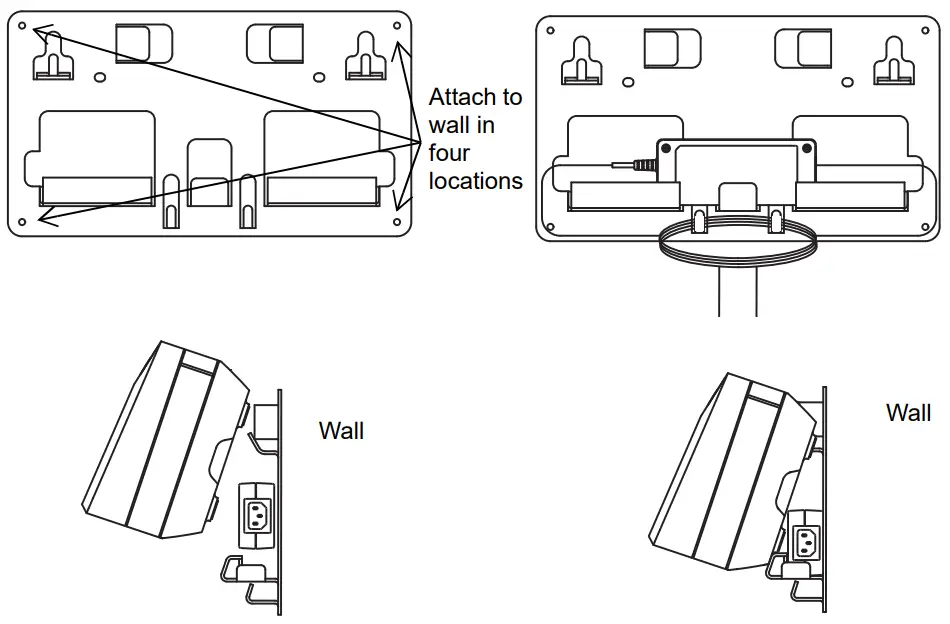
Figure 3: Mounting Multi-Unit Charger to Wall Bracket
Mounting Multi-Unit Charger to Wall Bracket
- Position the wall mount bracket in the desired position, and mark the location of the mounting holes on the wall surface.
 Ensure the area behind the mounting surface is always free of electrical wires, cables, and pipes before cutting, drilling, or installing the mounting screws.
 - Mount bracket to wall using the appropriate mounting hardware required for the type of wall material fixture it is being mounted to. Drill based on the marked mounting holes on the wall surfaces.
- Secure the wall bracket in position by installing mounting hardware over the mounting holes on the wall bracket tightly.
Note: It is recommended to use 10-16×1-1/2” tapping screw and washer (not included) on wood stud and solid-flat concrete/brick wall. - Hang the MUC on wall bracket as shown in Figure 3.
 Ensure the area behind the mounting surface is always free of electrical wires, cables, and pipes before cutting, drilling, or installing the mounting screws.
Additional Features and Information
The complete online user guide is available through publication part number MN003725A01 at https://www.motorolasolutions.com/content/learning/en_us/documentation-portal/accessories-_-energy/chargers.html. This guide provides information on features of the IMPRES 2™ Maintenance Multi-Unit Chargers.
![]()
![]()
EU Contact:
Motorola Solutions, Czerwone Maki 82,
30-392 Krakow, Poland.
MOTOROLA, MOTO, MOTOROLA SOLUTIONS, and the Stylized M Logo are trademarks or
registered trademarks of Motorola Trademark Holdings, LLC and are used under license.
All other trademarks are the property of their respective owners.
© 2017 and 2020 Motorola Solutions, Inc. All rights reserved.
 Printed in