![]() Systems
Systems
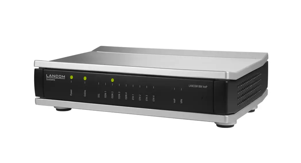
LANCOM 884 VoIP
Quick Reference Guide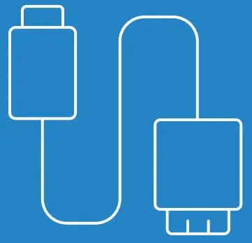
![]()
884 VoIP Router
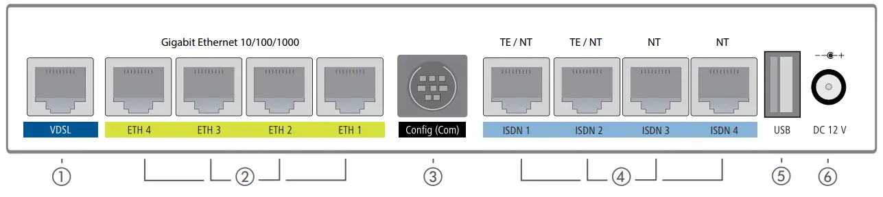
- VDSL interface
Use the supplied DSL cable for the IP-based line to connect the VDSL interface and the provider’s telephone socket. For more information, please contact your Internet service provider.
- Ethernet interfaces
Connect one of the interfaces ETH 1 to ETH 4 to your PC or a LAN switch.
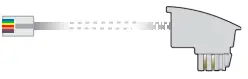
- Serial interface
Configuring the device via the serial interface requires a serial configuration cable (available as an accessory).
- ISDN interfaces
ISDN 1 + 2
Internal (NT) or external (TE) ISDN-S0 bus. This feature is controlled by LCOS. ISDN 3 + 4
Internal (NT) ISDN-S0 bus.
A 100-Ohm resistor for line termination is switchable in LCOS. - USB interface
You can use the USB interface to connect a USB printer or a USB drive.
- Power
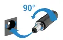
After connecting the cable to the device, turn the connector 90° clockwise to prevent it from accidental un plugging.
Use only the supplied power adapter. To prevent the device from overvoltage damage, an overvoltage-protected power supply is strongly recommended.
 To prevent the device from overvoltage damage, an overvoltage-protected power supply is strongly recommended.
 Please observe the following when setting up the device
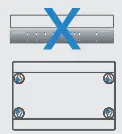
- Do not rest any objects on top of the device
- For devices to be operated on the desktop, please attach the adhesive rubber footpads
- In case of wall mounting, use the drilling template as supplied

- Keep the ventilation slots on the side of the device clearof obstruction
- Rack installation with the optional LANCOM Rack Mount (separately available)
Before initial startup, please make sure to take notice of the information regarding the intended use in the enclosed installation guide!
Operate the device only with a professionally installed power supply at a nearby power socket that is freely accessible at all times. 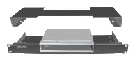
MOUNTING AND CONNECTING THE DEVICE
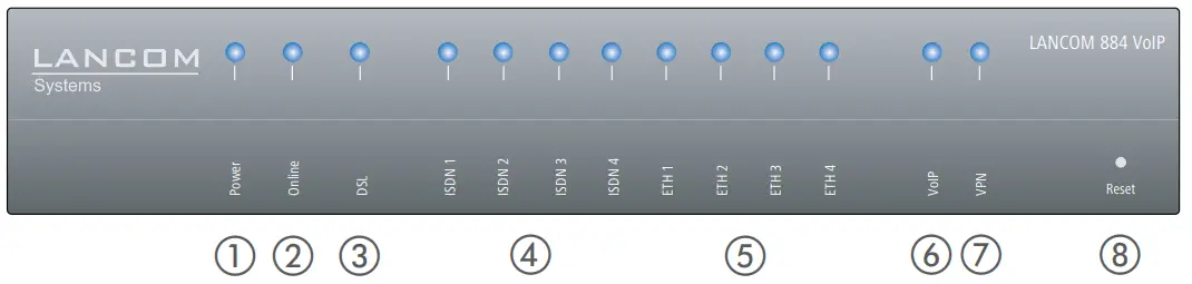
| Power | |
| Off | Device switched off |
| Green, permanently* | Device operational, resp. device paired / claimed and LANCOM Management Cloud (LMC) accessible |
| Green / red, blinking | No password set. Without a password the configuration data in the device is unprotected. |
| Red, blinking | Charge or time limit reached |
| lx green inverse blinking* | Connection to the LMC active, pairing OK, claiming error |
| 2x green inverse blinking* | Pairing error, resp. LMC activation code / PSK not available |
| 3x green inverse blinking* | LMC not accessible, resp. communication error |
| Online | |
| Off | WAN connection inactive |
| Green, blinking | WAN connection is established (e.g. PPP negotiation) |
| Green, permanently | WAN connection active |
| Red, permanently | WAN connection error |
| DSL | |
| Off | Interface deactivated |
| Green, permanently | DSL connection active |
| Green, flickering | DSL data transfer |
| Red, flickering | DSL transfer error |
| Red / orange, blinking | DSL hardware error |
| Orange, blinking | DSL training |
| Orange, permanently | DSL sync |
| Green, blinking | DSL connecting |
| ISDN | |
| Off | Interface deactivated |
| Green, permanently | D-channel active |
| Green, blinking | ISDN connected |
| Red, flickering | ISDN transfer error |
| Red / orange, blinking | ISDN hardware error |
| Red, permanently | ISDN connection not enabled |
| Orange, blinking | ISDN connecting |
| ETH | |
| Off | No networking device attached |
| Green, permanently | Connection to network device operational, no data traffic |
| Green, flickering | Data transmission |
| VolP | |
| Off | No SIP accounts defined or VCM is off |
| Green, permanently | All defined and active SIP accounts (outgo-ing) were successfully registered |
| Red, permanently | Not all of the defined and active SIP accounts were registered (possibly still in process) |
| Red or green, inverse flashing | Number of currently used lines (connecting or connected) |
| 0 VPN | |
| Off | VPN connection inactive |
| Green, permanently | VPN connection active |
| Green, blinking | VPN connecting |
| : Reset | |
| Reset button | Operated e.g. with a paper clip > short press: restart the device > long press: reset the device |
| Hardware | |
| Power supply | 12 V DC, external power adapter (230 V); bayonet connector to secure against disconnection |
| Power consumption | Max. ca. 14 W |
| Environment | Temperature range 0-40 °C; humidity 0-95 %; non-condensing |
| Housing | Robust synthetic housing, rear connectors, ready for wall mounting, Kensington lock; measures 210 x 45 x 140 mm (W x H x D) |
| Number of fans | None; fanless design, no rotating parts, high MTBF |
| Interfaces | |
| WAN: VDSL2 | > VDSL2 as per ITU G.993.2; profiles 8a, 8b, 8c, 8d, 12a, 12b, 17a > Compatible to VDSL2 from Deutsche Telekom > ADSL conformity according to: ADSL2+ over ISDN as per ITU G.992.5 Annex B/J with DPBO, ADSL2 over ISDN as per ITU G.992.3 Annex B, ADSL over ISDN as per ITU G.992.1 Annex B. > Supports one virtual connection at a time in ATM (VPI-VCI pair) |
| ETH | 4 individual ports, 10 / 100 / 1000 Mbps Gigabit Ethernet, by default set to switch mode. Up to 3 ports can be operated as additional WAN ports. Ethernet ports can be electrically disabled in the LCOS configuration. |
| USB | USB 2.0 hi-speed host port for connecting USB printers (USB print server), serial devices (COM-port server) or USB drives (FAT file system). |
| ISDN 1 / ISDN 2 ISDN 3/ ISDN 4 | ISDN 1+2: Internal (NT) or external (TE) ISDN bus. This feature is controlled by LCOS. ISDN 3+4: Internal (NT) ISDN bus. |
| Config (Com) / V.24 | Serial configuration interface / COM-port (8-pin mini-DIN): 9,600-115,200 baud, suitable for optional connection of analog / GPRS modems. Supports internal COM-port server and provides transparent asynchronous serial-data transfer via TCP. |
| WAN protocols | |
| VDSL, ADSL, Ethernet | PPPoE, PPPoA, IPoA, Multi-PPPoE, ML-PPP, PPTP (PAC or PNS) and IPoE (with or without DHCP), RIP-1, RIP-2, VLAN |
| ISDN | DSS1 (Euro-ISDN), PPP, X75, HDLC, ML-PPP, V.110 / GSM / HSCSD |
| Declaration of Conformity | |
| Hereby, LANCOM Systems GmbH | Adenauerstrasse 20/B2 | D-52146 Wuerselen, declares that this device is in compliance with Directives 2014/30/EU, 2014/53/EU, 2014/35/EU, 2011/65/EU, and Regulation (EC) No. 1907/2006. The full text of the EU Declaration of Conformity is available at the following Internet address: www.lancom-systems.com/doc | |
| Package content | |
| Manual | Quick Reference Guide (DE/EN), Installation Guide (DE/EN) |
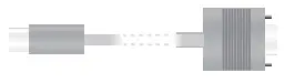
| Cable | 1 DSL cable for the IP-based line, 4.25m |
| Power adapter | External power supply adapter (230V), 12 V/ 1.5 A DC/S; barrel connector 2.1 / 5.5 mm bayonet; LANCOM item no. 111301 |
*) The additional power LED statuses are displayed in 5-seconds rotation if the device is configured to be managed by the LANCOM Management Cloud.
TECHNICAL DETAILS
This product contains separate open-source software components which are subject to their own licenses, in particular the General Public License (GPL). The license information for the device firmware (LCOS) is available on the device‘s WEBconfig interface under “Extras > License information“. If the respective license demands, the source files for the corresponding software components will be made available on a download server upon request.
LANCOM, LANCOM Systems, LCOS, LANcommunity and Hyper Integration are registered trademarks. All other names or descriptions used may be trademarks or registered trademarks of their owners. This document contains statements relating to future products and their attributes. LANCOM Systems reserves the right to change these without notice.
No liability for technical errors and/ or omissions. 111717/0122![]()


