SDC 700 ~ 800 Series Key Switches Installation Guide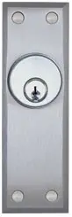
INSTALLATION INSTRUCTIONS
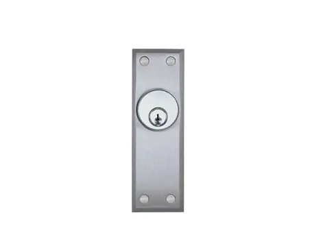
SDC Key Switch Assemblies are compatible with U.S. standard, mortise key cylinders and interchangeable core cylinders (not included). Standard switch assemblies are Single Gang box mounted (2-1/8″ depth required). Assemblies equipped with narrow faceplates are mounted directly to the door frame.
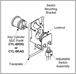
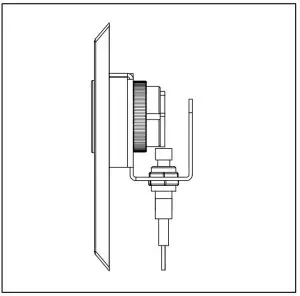
ASSEMBLY DETAIL
KEY SWITCH ASSEMBLY PROCEDURE
- Insert the key cylinder through the front of the faceplate. Make sure the key cylinder is oriented correctly and the tailpiece is in the upright position.
- While holding the key cylinder in place, slide the switch mounting bracket onto the back of the cylinder. Align the triangular tabs on the mounting bracket with the corresponding notches on the barrel of the key cylinder.
- Secure the key cylinder by screwing the supplied Locknut to the back of the cylinder. Tighten firmly. Insert key, adjust the switch position to ensure that the cam makes contact with the center of the switch plunger. The switch height should be adjusted so that the cam does not apply excessive downward pressure to the switch.
- Once the electrical connections are completed, mount the key switch assembly:
For the 700/800/800AL Series, attach to a single gang mortise or surface mounted box.
For the 700T/800T Series, attach to a double gang mortise or surface mounted box.
For the 700N/800N/800ALN Series, See the frame preparation illustrations on Page 2.
Use tailpiece supplied with SDC Part# CYL-KD, or Ilco 863G-00-10 Standard Cam equivalent.
ACTUAL SIZE
UL 294 Performance Rating
Level I: Line Security / Destructive Attack / Standby Power
Level IV: Endurance
Not all models verified by UL. 700 series evaluated by UL, 800 series were not evaluated.
STANDARD FEATURES
- Compatible with 1” to 1-3/8” standard and interchangeable core mortise key cylinders (not included).
- Key cylinder recessed for tamper resistance. (all except 700N Series).
- Tamper resistant spanner screws.
- Anti-tamper plugs (800 Series)
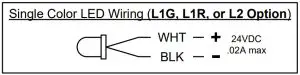
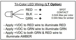
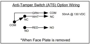
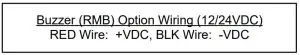
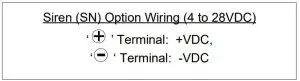
- Contact Rating: 2 amps @ 30VDC (Resistive/Inductive).
- Wire Leads: 7″, 22 gauge.
- Large actuator assembly for positive & consistent circuit activation.
- To be used with a Class 2 power supply or voltage compatible UL 294 or UL 603 listed power supply.
- Compliance with ANSI/NFPA 70 National Electrical Code.
OPTIONAL KEY CYLINDER
CYL-KD – 1.25″ Mortise Key Cylinder and (2) Keys.
Two different tailpieces included.
FACEPLATE DIMENSIONS
700: 4.5″H x 2.875″W x 20 Ga.
700N: 4.5″H x 1.75″W x 20 Ga.
700T: 4.5″H x 4.5″W x 20 Ga.
800/800AL: 5″H x 3.25″ W x 0.25″D
800N/800ALN: 5.5″H x 1.75″ W x 0.25″D
800T: 5″H x 5″ W x 0.25″D
ASSEMBLY TOOLS
For convenience, a small spanner tool is provided with the assembly for fastening of spanner security screws SS-632 Standard Spanner Screw Drivers are available.
Any suggestions or comments to this instruction or product are welcome. Please contact us through our website or email [email protected]
FRAME PREPARATION FOR NARROW KEY SWITCHES
Key switches fit a 1-3/4” frame. For jamb preparation make cut out as shown in Figure A OR Figure B. Using the faceplate as a template, drill and then tap for #6-32 screws. NOTE: FIGURES NOT TO SCALE
700N SERIES FRAME PREPARATION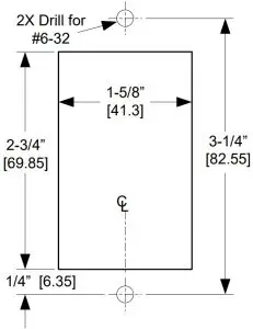
800N SERIES FRAME PREPARATION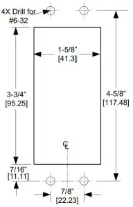
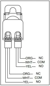
KEYSWITCH WIRING INSTRUCTIONS
FOR 700/700N/700T/800/800N/800T/800AL SERIES & OPTIONS:
SINGLE SPDT SWITCH WIRING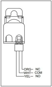
DUAL SPDT SWITCH WIRING