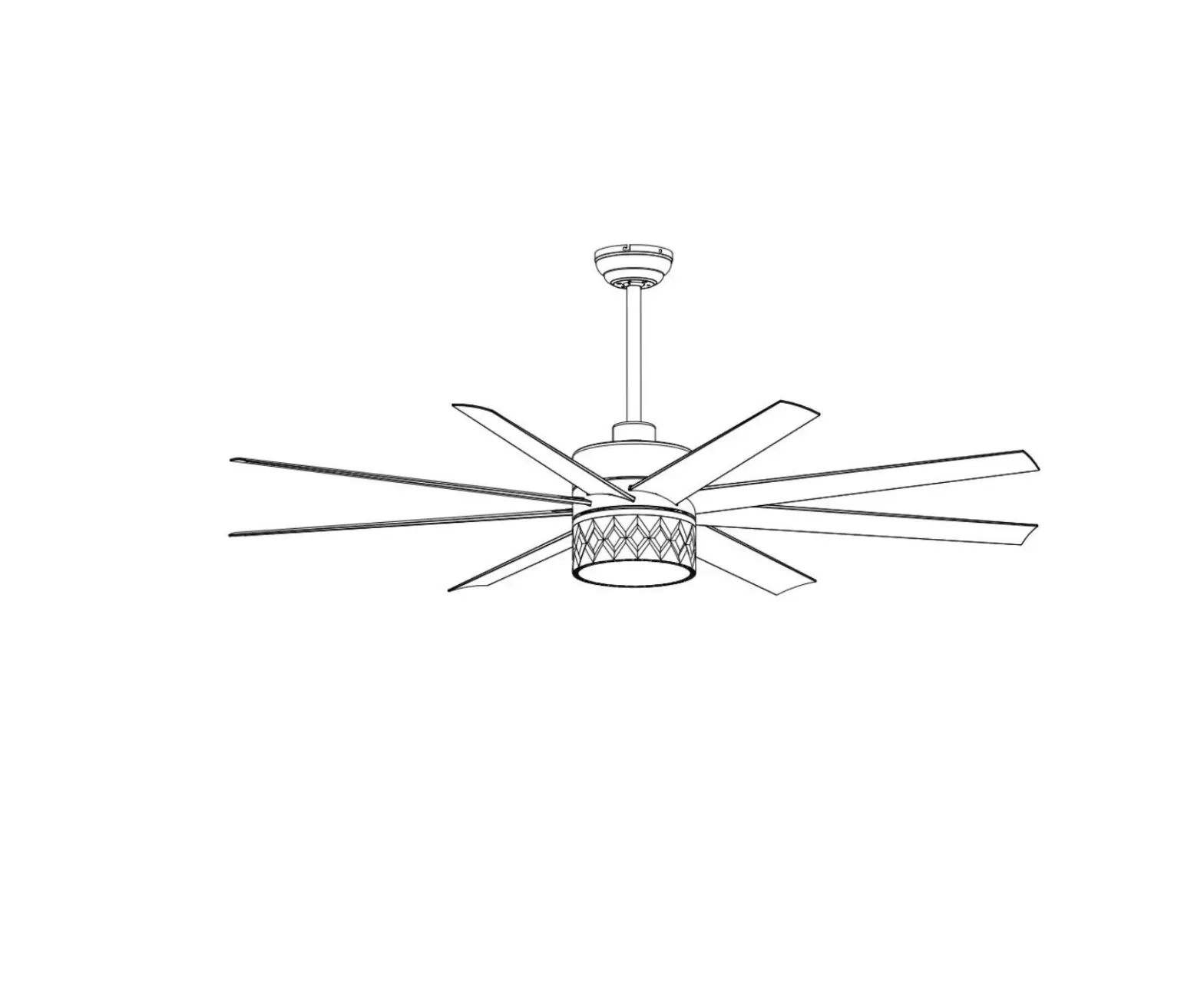
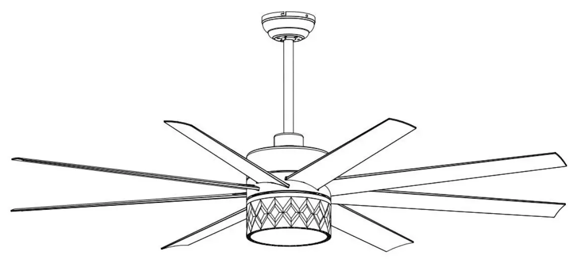
Breezary 29001 65 Inch Ceiling Fan with Light
Safety Information
- To reduce the risk of electric shock, ensure electricity has been turned off at the circuit breaker or fuse box before you begin.
- All wiring must be in accordance with the National Electrical Code “ANSI/NFPA 70” and local electrical codes. Electrical installation should be performed by a qualified licensed electrician.
- The outlet box and support structure must be securely mounted and capable of reliably supporting a minimum of 35 lbs (15.9 kg). Use only UL Listed outlet boxes marked “Acceptable for Fan Support of 35 lbs. (15.9 kg) or less.”
- Do not place objects in the path of the blades.
- To clean the fixture, turn off the power, wait for it to cool, and wipe the fixture with a clean, soft cloth.
- After making electrical connections, spliced conductors should be turned upward and pushed carefully up into the outlet box. The wires should be spread apart with the grounded conductor and the equipment- grounding conductor on one side of the outlet box and ungrounded conductor on the other side of the outlet box. where necessary before installation
- All setscrews must be checked and retightened.
![]() WARNING: To reduce the risk of electrical shock or fire,not use this fan with any solid-state fan speed control device. It will permanently damage the electronic circuitry.
WARNING: To reduce the risk of electrical shock or fire,not use this fan with any solid-state fan speed control device. It will permanently damage the electronic circuitry.
![]() WARNING: To reduce the risk of personal injury, do not bend the blade brackets when installing the rackets balancing the blades, or cleaning the fan. Do not insertforeign objects in between rotating fan blades.
WARNING: To reduce the risk of personal injury, do not bend the blade brackets when installing the rackets balancing the blades, or cleaning the fan. Do not insertforeign objects in between rotating fan blades.
![]() WARNING: To reduce the risk of fire, electric shock or personal injury, mount to outlet box marked “acceptable for fan support of 35 lbs. (15.9Kg) or less” and use screws provided with the outlet box.
WARNING: To reduce the risk of fire, electric shock or personal injury, mount to outlet box marked “acceptable for fan support of 35 lbs. (15.9Kg) or less” and use screws provided with the outlet box.
![]() WARNING: To avoid possible electrical shock, turn the electricity off at the main fuse box before wiring.
WARNING: To avoid possible electrical shock, turn the electricity off at the main fuse box before wiring.
![]() WARNING: To reduce the risk of electrical shock, this must be installed with an isolating wall control/switch.
WARNING: To reduce the risk of electrical shock, this must be installed with an isolating wall control/switch.
![]() CAUTION: To reduce the risk oxf personal injury, use only the screws provided with the outlet box.
CAUTION: To reduce the risk oxf personal injury, use only the screws provided with the outlet box.
![]() CAUTION: Please use carefully when working around or cleaning the fan to avoid injury or damage of fan.
CAUTION: Please use carefully when working around or cleaning the fan to avoid injury or damage of fan.
![]() CAUTION: The fan must be mounted with a minimum of 7 ft (2. 1 m) clearance from the trailing edge of the blades to the floor.
CAUTION: The fan must be mounted with a minimum of 7 ft (2. 1 m) clearance from the trailing edge of the blades to the floor.
![]() CAUTION: Changes or modifications not expressly approved by the party responsible for compliance could void the user’ s authority to operate the equipment.
CAUTION: Changes or modifications not expressly approved by the party responsible for compliance could void the user’ s authority to operate the equipment.
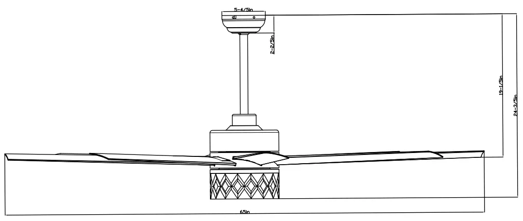
Dimension Reference
Hardware Included
| Hardware Package | Quantity | |
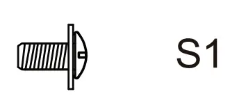 | S1. Blade Screw | 25 |
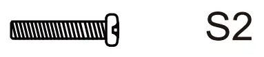 | S2. Machine Screw | 2 |
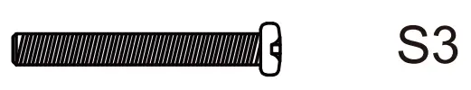 | S3. Machine Screw | 2 |
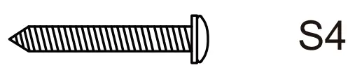 | S4. Wood Screw | 2 |
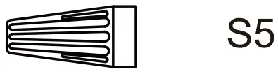 | S5. Wire Nut | 3 |
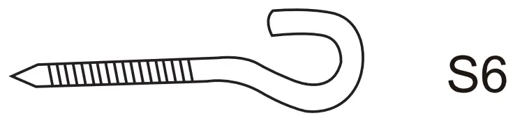 | S6. J-hook | 1 |
 | S7. Lock Washer | 4 |
 | S8. Star Washer | 2 |
 | S9. Washer | 4 |
 | S10.Paper Washer | 25 |
 | S11.Screw | 2 |
 | S12.Lock Washer | 2 |
Fan Parts Included
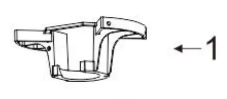 | Mounting Bracket | 1 |
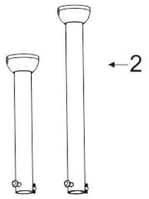 | Downrod | 2 |
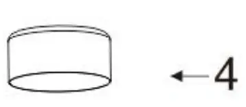
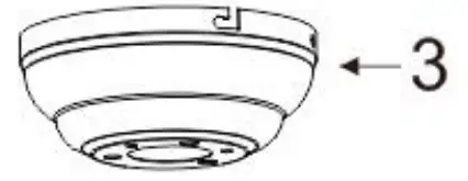 | Canopy | 1 |
 | Yoke Cover | 1 |
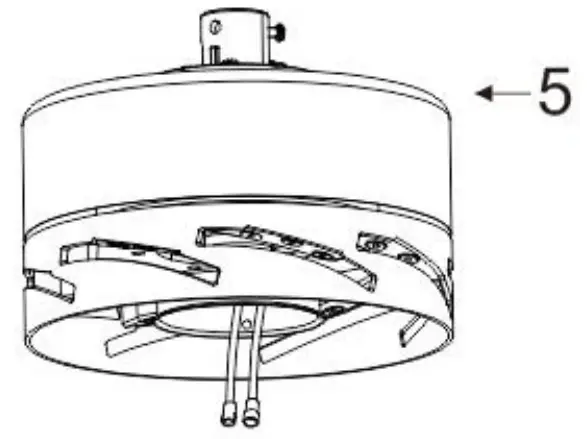 | Motor Assembly | 1 |
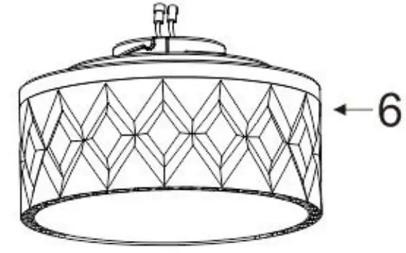 | Light kit | 1 |
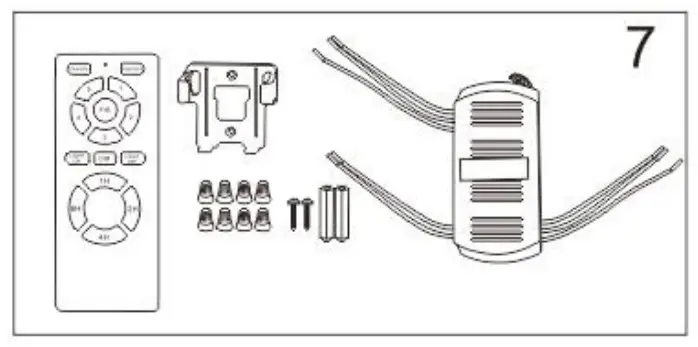 | Remote Control( Batteries not included) | 1 |
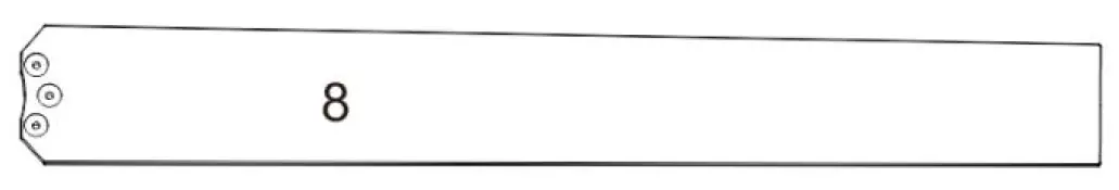 | Blade | 8 |
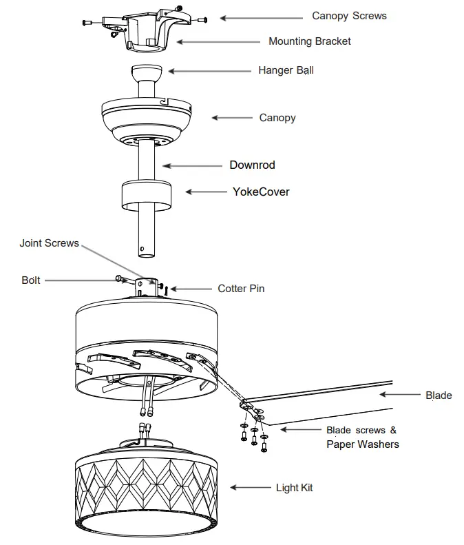
Exploded View
Installation Instructions
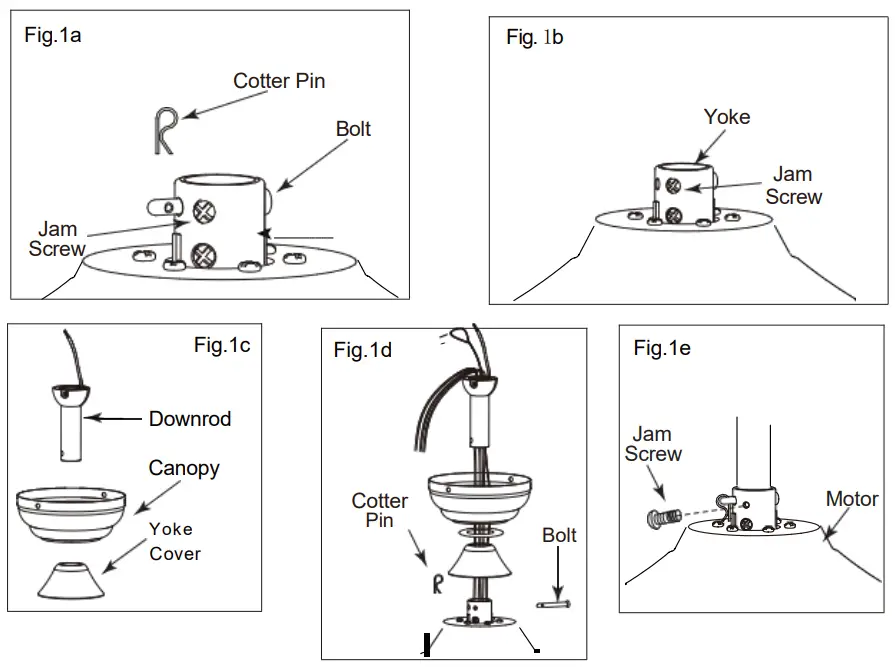
Step1 MOUNTING
- Take out fan motor housing.
- Remove cotter pin and bolt from yoke.
- Loosen jam screw in yoke until it is flush with the inside surface.
- Obtain downrod, canopy and yoke cover.
- Place downrod inside canopy and yoke cover.
- Route wires exiting motor through yoke cover, canopy and downrod.
- Insert bolt through hole in and downrod. Be careful not to damage or cut the fan wires.
- Tighten bolt. Secure with cotter pin through hole in the end of the bolt.
- Secure downrod in position by tightening jam screws. Slide yoke cover down and it will flush with the motor housing
CAUTION : To ensure wobble – free operation and to avoid damage to the fan, the downrod and the set crew must be completely tightened
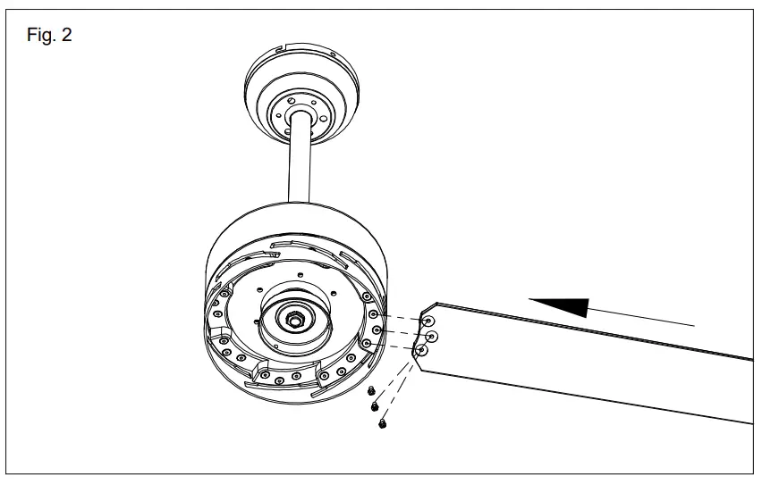
Step2 MOUNTING BLADES TO MOTOR
- Insert the blade into the fan as shown.
- Tighten the blade to motor with the screw and lock washer as shown
- Slightly turn the blade after installation and repeat the same step for the other blades.

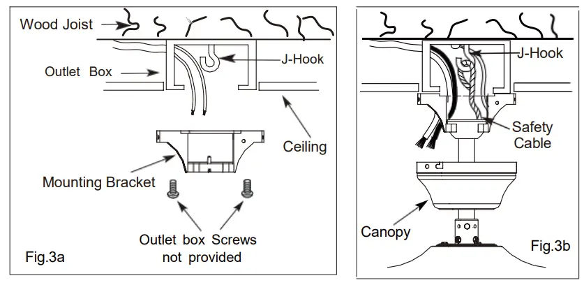
Step3 MOUNTING BRACKET TO MOTOR
WARNING: To Reduce The Risk Of Fire, Electric Shock, Or Personal Injury, Mount To UL/CSA Listed Outlet Box Marked Acceptable for Fan Support And Use Mounting Screws Provided With The Outlet Box.
- Install J-Hook through centre of outlet box and into the wooden joist.
- Secure mounting bracket and rubber gaskets to metal outlet box.
- Hang the safety cable onto the J-hook.

Step4 ELECTRICAL HOOK-UP
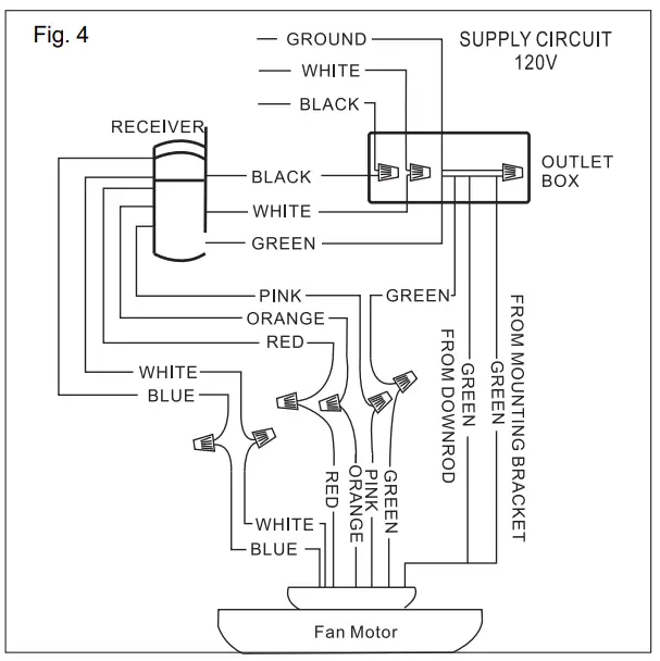
A.Make the following wire connections to the receiver unit (see fig. 4) using the wire nuts supplied.
- Connect GREEN fan wire to BARE (ground) wire.
- Connect BLACK receiver unit wire to BLACK supply wire.
- Connect WHITE receiver unit wire to WHITE supply wire.
- After making the wire connections, ensure the wires should be spread apart with the grounded conductor and the equipment-grounding conductor on one side of the outlet box and the ungrounded conductor on the other side of the outlet box.
- Ensure the splices after being made should be turned upward and pushed carefully up into the outlet box.
- Connect the 4-Wire female and male plug.
- Connect the 2-Wire female and male plug

NOTE: Once ground wires are connected, carefully tuck all wires and wire nuts into the metal outlet box making sure that the wires are clear of the hemisphere and downrod when positioned in mounting bracket.
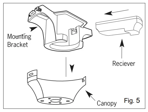
B. Push all connected wires up into ceiling box.
- Position the receiver into the mounting bracket as shown direction.
- When installing the canopy, ensure the antenna is not pressed by the canopy.- Ensure to connect all ground wires accordingly.

C. FUNCTION INSTRUCTION OF EMITTER
Learning code and matching mode is used between transmitter and receiver.
- Open battery cover on the hand-held remote and install battery, pair of AAA of emitter (1.5V) that are not included.
- Turn “ON” the supply power. Within 30 seconds, press “FAN ON/OFF” button on the transmitter for 5 seconds. Transmitter and receiver are connected after hearing a long “beep”.
- If the transmitter cannot control the fan, check to ensure all wiring connections are properly connected according to the instruction manual. Check to ensure the batteries are in the right position. Check whether there are any similar remote controls in use nearby. Check whether they work with the same frequency.
- Low voltage of battery will affect the sensitivity of the transmitter. The indicator light will flash when battery voltage is low. Replace the batteries for better performance.
- Take out the batteries from the transmitter when leaving unused for long periods of time.
- Ensure to connect the ground wire accordingly
Remote control instruction
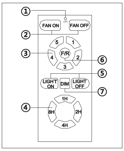
- LED indicated light
- ON/OFF the fan
- Speed of the fan ( ① low speed- ⑤ high speed)
- Timing control of the fan
- Short press: ON/ OFF the light
- Direction of the fan (reverse switch)
- Long press (hold for 3 seconds): Dimming
Step5 MOUNTING FAN ASSEMBLY
- Place two screws and washers on mounting plate (marked B on diagram) which correspond with slots in canopy. Screw in two turns .
- Position canopy to mounting plate aligning slots to screws (marked B on diagram) then turn to lock .
Step6 ENGAGE HEMISPHER
- Position and tighten the two screws and washers (marked A on diagram) then tighten the two screws (marked B on diagram)
- Carefully rotate fan assembly until groove in hemisphere locks over tab of canopy assembly.
WARNING: Failure to seat tab in groove could cause damage to electrical wires and possible shock or ire hazard.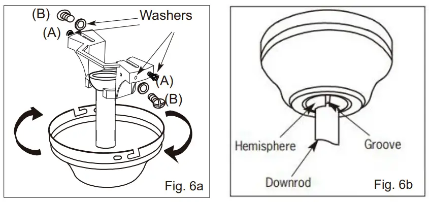
NOTE: When installing fan on sloped ceiling, make sure tab on hanger bracket faces towards the top of the slope. Depending on the slope, a longer downrod may be required to prevent fan blades from hitting the ceiling.
Step7 LIGHT KIT
WARNING: BE SURE TO TURN OFF POWER BEFORE INSTALLING
- Connect polarized connectors of light kit to corresponding connectors found in switch housing(connect WHITE light kit unit wire to WHITE fan wire, connect BLUE light kit unit wire to BLUE fan wire)
- Loosen the screw on the light kit,thread one end of the light kit safety cable through the knotted ring of the fan safety cable,then through the light kit safety cable screw nut hole,an tighten the screw to lock.
- Place the light kit(hold the metal part instead of acrylic ) onto the fan and turn to secure.

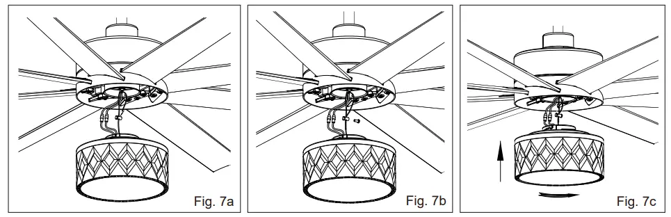
WARNING: When installing the light kit, hold the metal part of the light kit and turn to secure. Do not hold the acrylic part and that may cause the light kit installed tightened enough
Troubleshooting Guide
If you have difficulty operating your new ceiling fan it may be the result of incorrect assembly, installation, or wiring. In some cases these installation errors may be mistaken for defects. If you experience any faults please check this troubleshooting guide.
| Problem | Suggested Remedy | |
| 1 | If fan does not start. |
|
| 2 | If fan sounds noisy. |
|
| 3 | If fan wobbles. |
|
| 4 | If light does not work. |
|


