Introduction
The INS401’s FW can be upgraded by using acenav CLI Software and the Ethernet interface.
Items needed to upgrade the firmware are:
- PC running Windows 8 or later with RJ45 Port
- 100base-T1 to Tx adapter board
- Power Source (12V)
- acenav-cli v2.6.5 or later
- PowerShell
- Binary(s):
- INS401_v28.01.bin as example
Instructions to update new FW
- Save FW binary file(s) to be installed into a folder on PC
where you can locate them later for installation. - Download Aceinna’s official SW acenav.exe, link
- Power on INS401
- Connect INS401(3-ETH_TRX_N-, 4-ETH_TRX_P+) by ethernet transfer board (100base-T1 to Tx) or similar instrument, then the board should be connected with PC by network cables
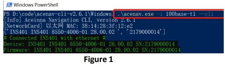
- Run PowerShell on the same folder as acenav.exe, then input command ‘.\acenac.exe –i 100base-t1 –cli’ to run acenav.exe in CLI mode, see in Figure 1, after this # Console display with connection information # Prompt for user input, type in a command and file path after the arrow symbol.

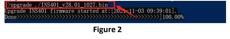
- Input update command ‘upgrade ’, see in Figure 2, when console shows ‘done 100%’ upgrade is finished.

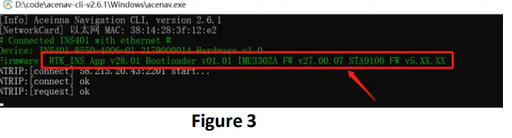
- After the firmware update is complete, reconnect the device, and check the FW version in the connection information, see in Figure 3, if the FW version is right, it means update successfully.

Main Connector and Pin Description
The main connector carries all the other power and I/O signals to and from the INS401 module. This connector is also of automotive grade and is manufactured by JAE Electronics. The male end which is installed in the INS401 housing has part number MX23A18NF1; the female end, which is attached to the external wiring harness, has part number MX23A18SF1. Figure 1 illustrates the location of the 18 pins in the male part, as seen facing the connector from outside the module.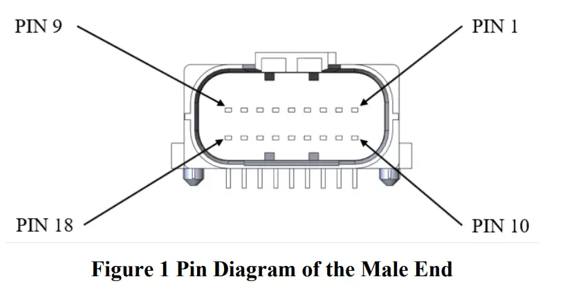
Table 1 shows the functional description of the 18 pins in the main connector.
Table 1 Pin Description of the Main Connector
| Pin Number | Type | Pin Name | Pin Function |
| 1 | Reserved | N/A | Reserved |
| 2 | Reserved | N/A | Reserved |
| 3 | I/O | ETH_TRX_N | Ethernet (negative) |
| 4 | I/O | ETH_TRX_P | Ethernet (positive) |
| 5 | Reserved | N/A | Reserved |
| 6 | Reserved | N/A | Reserved |
| 7 | Reserved | N/A | Reserved |
| 8 | Reserved | N/A | Reserved |
| 9 | Power | VCC_IN | 9V ~ 32V DC power input |
| 10 | Reserved | N/A | Reserved |
| 11 | Reserved | N/A | Reserved |
| 12 | Reserved | N/A | Reserved |
| 13 | Reserved | N/A | Reserved |
| 14 | Power | GND | Negative power supply input |
| 15 | Power | GND | Negative power supply input |
| 16 | O | PPS | 1 Pulse per Second output, synchronized to GNSS |
| 17 | Power | GND | Negative power supply input |
| 18 | Power | GND | Negative power supply input |
ACEINNA, Inc. ♦ 1 Tech Drive, Suite 325 Andover, MA 01810 ♦ T: +1 978-965-3200 ♦ F: +1 978-965-3201 ♦ www.aceinna.com


