![]()
AcraDyne iAC4EGV-T Assignable I O Gen IV ACE iAC Controller 
Assignable I/O
The Gen IV controller supports assignable I/O.
Buses: The controller is divided up into buses. Each bus has a set of inputs and a set of outputs. Currently the controller supports the following buses.
| Bus Number | Bus |
| 1 | Physical I/O |
| 2 | Fieldbus (Anybus module) I/O |
| 3 | Modbus TCP |
| 4 | Ethernet/IP |
All assignments have a bus, element, and bit configuration to define its location in the system. The bus value needs to be set from the list above. The element and bit define the location in the bus. The first element on the bus is 0 and goes up the last legal element for the given bus. The bits in each element is referenced from 0(LSB) to 31(MSB).
Inputs
All input assignments have a Bus, Element, and Bit configuration to define its location in the system. Along with the basic configuration many also have other configuration(s) that allow its behavior to be modified to suit the application.
| Supported Feature | Controllers | ||||||||||
| Bus | Element | Bit 0-31 | Polarity N.O./N.C. | Width | Offset | iEC | iAC | iPC | iBC | iBC-Z | |
| Do Nothing | √ | √ | √ | √ | √ | √ | √ | √ | |||
| Start | √ | √ | √ | √ | √ | ||||||
| Stop | √ | √ | √ | √ | √ | √ | √ | √ | |||
| Reverse | √ | √ | √ | √ | √ | ||||||
| Disable | √ | √ | √ | √ | √ | √ | √ | ||||
| Reset Job | √ | √ | √ | √ | √ | √ | √ | √ | √ | ||
| Select PSet | √ | √ | √ | √ | √ | √ | √ | √ | √ | ||
| Select Job | √ | √ | √ | √ | √ | √ | √ | √ | √ | √ | |
| Select Job Sequence | √ | √ | √ | √ | √ | √ | √ | √ | √ | √ | |
| Disable Assembly | √ | √ | √ | √ | √ | ||||||
| Set ID | √ | √ | √ | √ | √ | √ | √ | √ | √ | ||
| Set ID (word swap) | √ | √ | √ | √ | √ | √ | √ | √ | √ | ||
| Set Date/Time | √ | √ | √ | √ | √ | √ | √ | √ | √ | ||
| Set Date/Time (word swap) | √ | √ | √ | √ | √ | √ | √ | √ | √ | ||
| Verify PSet | √ | √ | √ | √ | √ | √ | √ | √ | √ | √ | |
| Clear Results | √ | √ | √ | √ | √ | √ | √ | √ | √ | ||
| Log Change | √ | √ | √ | √ | √ | √ | √ | √ | √ | √ | |
| Decrement Batch | √ | √ | √ | √ | √ | √ | √ | √ | √ | ||
| Increment Batch | √ | √ | √ | √ | √ | √ | √ | √ | √ | ||
| Click Wrench | √ | √ | √ | √ | √ | √ | √ | √ | √ | ||
| Bypass Stops | √ | √ | √ | √ | √ | √ | √ | √ | √ | ||
| Verify Job Sequence | √ | √ | √ | √ | √ | √ | √ | √ | √ | √ | |
| ASCII ID | √ | √ | √ | √ | √ | √ | √ | ||||
| Abort Job | √ | √ | √ | √ | √ | √ | √ | √ | |||
| Remote Start | √ | √ | √ | √ | √ | ||||||
| Remove Lock on Reject | √ | √ | √ | √ | √ | √ | √ | √ | |||
| Dual Start Interlocked | √ | √ | √ | √ | √ | ||||||
| Decrement Job | √ | √ | √ | √ | √ | √ | √ | √ | √ | ||
| Increment Job | √ | √ | √ | √ | √ | √ | √ | √ | √ | ||
| Decrement PSet | √ | √ | √ | √ | √ | √ | √ | √ | √ | ||
| Increment PSet | √ | √ | √ | √ | √ | √ | √ | √ | √ | ||
| Decrement Job Sequence | √ | √ | √ | √ | √ | √ | √ | √ | √ | ||
| Increment Job Sequence | √ | √ | √ | √ | √ | √ | √ | √ | √ | ||
Polarity
When the polarity is set to N.O. the input is considered active high (24vdc for physical inputs and logic 1 for all network type buses). When the polarity is set to N.C. the input is considered active low (0vdc for physical inputs and logic 0 for all network type buses).
Width and Offset
For multiple bit inputs (for example “Select PSet”) the width variable defines the number of bits the assignment will read for its input. This allows the input size to be restricted to a few bits saving space for other assignments.
The offset variable allows a fixed value to be added to the read value.
For example to use bits 4 & 5 of the physical inputs to select parameter sets 1-4 the assignment would look like…
| Select PSet | ||
| Bus | 1 | For the physical bus |
| Element | 0 | For the first element on the bus |
| Bit | 4 | For the starting bit location |
| Width | 2 | To span the two bits 4 & 5 |
| Offset | 1 | Adding 1 to the read input value so we get… Binary 00 = 1 Binary 01 = 2 Binary 10 = 3 Binary 11 = 4 |
Input Assignments
| Do Nothing | Bus | Element | Bit 0-32 | Polarity N.O./N.C. | Width | Offset |
| √ | √ | √ | ||||
| The “Do Nothing” assignment will run do nothing if it is active or inactive. | ||||||
| Start | Bus | Element | Bit 0-32 | Polarity N.O./N.C. | Width | Offset |
| √ | √ | √ | √ | |||
| The “Start” assignment will run the tool while the input is active. Start is available for the Physical I/O bus only. | ||||||
| Stop | Bus | Element | Bit 0-32 | Polarity N.O./N.C. | Width | Offset |
| √ | √ | √ | √ | |||
| The “Stop” assignment will stop the tool if it is running and prevent it from being started. | ||||||
| Reverse | Bus | Element | Bit 0-32 | Polarity N.O./N.C. | Width | Offset |
| √ | √ | √ | √ | |||
| The “Reverse” will put the controller in disassembly mode while the input is active. | ||||||
| Disable | Bus | Element | Bit 0-32 | Polarity N.O./N.C. | Width | Offset |
| √ | √ | √ | √ | |||
| The “Disable” will disable the tool while the input is active. It will not stop a fastening cycle that is progress. | ||||||
| Reset Job | Bus | Element | Bit 0-32 | Polarity N.O./N.C. | Width | Offset |
| √ | √ | √ | √ | |||
| On the transition of inactive to active the “Reset Job” assignment will reset the active job. | ||||||
| Select PSet | Bus | Element | Bit 0-32 | Polarity N.O./N.C. | Width | Offset |
| √ | √ | √ | √ | √ | ||
| The “Select PSET” input will select the parameter set according to the input value. Uses the width parameter limit the width of the input bits read. The minimum width is 1 and the maximum is 8. After the input is read the offset parameter will be added to the value do get the actual parameter set number. Selecting an invalid parameter set number will disable the tool. | ||||||
| Select Job | Bus | Element | Bit 0-32 | Polarity N.O./N.C. | Width | Offset |
| √ | √ | √ | √ | √ | ||
| The “Select Job” input will select the job number according to the input value. Uses the width parameter limit the width of the input bits read. The minimum width is 1 and the maximum is 8. After the input is read the offset parameter will be added to the value do get the actual job number. Selecting an invalid job number will disable the tool. | ||||||
| Select Job Sequence | Bus | Element | Bit 0-32 | Polarity N.O./N.C. | Width | Offset |
| √ | √ | √ | √ | √ | ||
| The “Select Job Sequence” input will select the job sequence number according to the input value. Uses the width parameter limit the width of the input bits read. The minimum width is 1 and the maximum is 8. After the input is read the offset parameter will be added to the value do get the actual job sequence number. Selecting an invalid job sequence number or a sequence that is already complete will disable the tool. | ||||||
| Disable Assembly | Bus | Element | Bit 0-32 | Polarity N.O./N.C. | Width | Offset | Set Date/ Time (word swap) | Bus | Element | Bit 0-32 | Polarity N.O./N.C. | Width | Offset | |||
| √ | √ | √ | √ | √ | √ | √ | √ | |||||||||
| The “Disable Assembly” assignment will disable the tool in the assembly direction. It will not disable the tool in disassembly or tube nut homing. It w ill not stop a fastening cycle that is progress. | The “Set Date/Time (word swap)” assignment is the same as the “Set Date/Time” assignment except the high and low words (16bit) are swapped prior to evaluation. This is to correct the mixed endianness of some PLC. See the “Set Date/Time” for behavior. | |||||||||||||||
| Set ID | Bus | Element | Bit 0-32 | Polarity N.O./N.C. | Width | Offset | ||||||||||
| √ | √ | √ | √ | |||||||||||||
| Verify PSet | Bus | Element | Bit 0-32 | Polarity N.O./N.C. | Width | Offset | ||||||||||
| The “Set ID” assignment will set the ID to an integer value of the input value. The width can be set from 1 to 32 bits. The input value will read as an integer value and an ASCII string with leading zeros will be produced and passed to the ID recognition system. The length of the string is based on the width of the assignment. The string will always be sized to accommodate the maximum value of the input. For example a width setting of 16 can have an integer value of 0-65535 so the produced ID would be “00000” to “65535” (always five character long). | ||||||||||||||||
| √ | √ | √ | √ | √ | ||||||||||||
| The “Verify PSET” input will compare the current parameter set to the input value. Uses the width parameter limit the width of the input bits read. The minimum width is 1 and the maximum is 8. After the input is read the offset parameter will be added to the value do get the actual parameter set number. If the parameter set input value does not match the current parameter of the controller the tool will be disabled. | ||||||||||||||||
| Width Length of setting ID string ID value | ||||||||||||||||
| Clear Results | Bus | Element | Bit 0-32 | Polarity N.O./N.C. | Width | Offset | ||||||||||
| 1 – 3 | 1 | “0” – “n” | √ | √ | √ | √ | ||||||||||
| The “Clear Results” assignment will clear the latest results outputs (Ok, Nok, etc.) on the same bus. | ||||||||||||||||
| 4 – 6 | 2 | “00” – “nn” | ||||||||||||||
| 7 – 9 | 3 | “000“ – “nnn” | ||||||||||||||
| 10 – 13 | 4 | “0000” – “nnnn” | ||||||||||||||
| Log Change | Bus | Element | Bit 0-32 | Polarity N.O./N.C. | Width | Offset | ||||||||||
| 14 – 16 | 5 | “00000” – “nnnnn” | ||||||||||||||
| √ | √ | √ | √ | √ | ||||||||||||
| 17 – 19 | 6 | “000000” – “nnnnnn” | ||||||||||||||
| The “Log Change” assignment will add entries to the controller event log when the input changes. | ||||||||||||||||
| 20 – 23 | 7 | “0000000” – “nnnnnnn” | ||||||||||||||
| 24 – 26 | 8 | “00000000” – “nnnnnnnn” | ||||||||||||||
| 27 – 29 | 9 | “000000000” – “nnnnnnnnn” | ||||||||||||||
| Decrement Batch | Bus | Element | Bit 0-32 | Polarity N.O./N.C. | Width | Offset | ||||||||||
| 30 – 32 | 10 | “0000000000” – “nnnnnnnnnn” | ||||||||||||||
| √ | √ | √ | √ | |||||||||||||
| The “Decrement Batch” assignment will remove the latest OK rundown from the current running JOB. This will cause the JOB count to be reduced by one. | ||||||||||||||||
| Set ID (word swap | Bus | Element | Bit 0-32 | Polarity N.O./N.C. | Width | Offset | ||||||||||
| √ | √ | √ | √ | |||||||||||||
| The “Set ID (word swap)” assignment is the same as the “Set ID” assignment except the high and low words (16bit) are swapped prior to evaluation. This is to correct the mixed endianness of some PLC. See the “Set ID” for behavior. | ||||||||||||||||
| Increment Batch | Bus | Element | Bit 0-32 | Polarity N.O./N.C. | Width | Offset | ||||||||||
| √ | √ | √ | √ | |||||||||||||
| The “Increment Batch” assignment will insert a manual rundown into the current sequence of the current JOB. This will cause the JOB count to increment by one. | ||||||||||||||||
| Set Date/ Time | Bus | Element | Bit 0-32 | Polarity N.O./N.C. | Width | Offset | ||||||||||
| √ | √ | √ | √ | |||||||||||||
| The “Set Date/Time” assignment will set the date and time of the controller. The width can be set from 1 to 32 bits but should always be set to 32 to get the correct results. The input value will be read as the number of seconds since 00:00:00 January 1, 1970 (POSIX time or Epoch time). If the input value changes and it is non-zero the date and time of the controller will be set to the new value. | ||||||||||||||||
| Click Wrench | Bus | Element | Bit 0-32 | Polarity N.O./N.C. | Width | Offset | ||||||||||
| √ | √ | √ | √ | |||||||||||||
| The “Click Wrench” assignment is the same as “Increment Batch” with the addition of a programmable torque value. | ||||||||||||||||
| Bypass Stops | Bus | Element | Bit 0-32 | Polarity N.O./N.C. | Width | Offset | Dual Start Interlocked | Bus | Element | Bit 0-32 | Polarity N.O./N.C. | Width | Offset | ||
| √ | √ | √ | √ | √ | √ | √ | √ | ||||||||
| The “Bypass Stops” assignment removes most stop conditions, allowing the tool to be ran in an override type condition. Hardware faults, stop and disable inputs are not removed. | |||||||||||||||
| The “Dual Start Interlocked” assignment will run the tool if the interlock conditions are met. Dual Start Interlock is available for the Physical IO bus only. The Dual Start Interlocked input works in combination with the Physical input assigned to the ‘Start’ input. The Dual Start Interlocked is only available for iEC controllers. | |||||||||||||||
| Verify Job Sequence | Bus | Element | Bit 0-32 | Polarity N.O./N.C. | Width | Offset | |||||||||
| √ | √ | √ | √ | √ | |||||||||||
| Setup • Only 1 Start Input and 1 Dual Start Interlocked Input should be assigned. • Controller->Tool Setup –> Start Input Configuration: ○ The Start Input Source Must be set to ‘Start From IO’. ○ Latching throttle is disabled for Dual Interlocked Start.
Dual Start Interlocked – Operation • The tool will not run unless both inputs are activated within two seconds of each other. • If the two second timer times out, both inputs must be deactivated to reset the timer. • If either input is deactivated the tool stops. • To restart the tool, both inputs must be deactivated then reactivated within two seconds of each other.
Tubenut Tool Homing Exceptions for Dual Start Interlocked functionality • If controller’s tubenut homing configuration is set to RELEASE: ○ Deactivating either, or both, of the inputs will initiate the homing sequence. ○ Homing will continue until sequence is complete. • If controller’s tubenut homing configuration is set to RELEASE AND REPRESS: ○ Deactivating either of the inputs, then activating both inputs will initiate the homing sequence. ○ Homing will continue while both inputs are active. ○ If either input is deactivated, before homing is complete, the tool will stop, and homing will pause until both inputs are reactivated. ○ To restart tool, after homing is complete, both inputs must be deactivated, then reactivated within two seconds of each other. | |||||||||||||||
| The “Verify Job Sequence” input will compare the current Job sequence to the input value. Uses the width parameter limit the width of the input bits read. The minimum width is 1 and the maximum is 8. After the input is read the offset parameter will be added to the value do get the actual Job sequence number. If the Job sequence input value does not match the current Job sequence of the controller the tool will be disabled. | |||||||||||||||
| ASCII ID | Bus | Element | Bit 0-32 | Polarity N.O./N.C. | Width | Offset | |||||||||
| √ | √ | ||||||||||||||
| The “ASCII ID” assignment will set the ID to the of the input (ASCII) value. This assignment consumes the entire element so the Bit is not used. It also has a length parameter to set the length of the input in bytes. The input value will be passed directly to the ID recognition system. | |||||||||||||||
| Abort Job | Bus | Element | Bit 0-32 | Polarity N.O./N.C. | Width | Offset | |||||||||
| √ | √ | √ | √ | ||||||||||||
| The “Abort Job” assignment aborts the job and disables the tool. A job reset is required to enable the tool for the next job. | |||||||||||||||
| Remote Start | Bus | Element | Bit 0-32 | Polarity N.O./N.C. | Width | Offset | |||||||||
| √ | √ | √ | √ | ||||||||||||
| The “Remote Start” assignment will run the tool while the input is active. Remote Start is available for non-physical I/O buses. | |||||||||||||||
| Remove Lock on Reject | Bus | Element | Bit 0-32 | Polarity N.O./N.C. | Width | Offset | |||||||||
| √ | √ | √ | √ | ||||||||||||
| The “Remove Lock on Reject” assignment unlocks the tool if locked on reject, re-enabling the tool. | |||||||||||||||
| Decrement Job | Bus | Element | Bit 0-32 | Polarity N.O./N.C. | Width | Offset |
| √ | √ | √ | √ | |||
| The “Decrement Job” assignment will decrement the Job Number, selecting the last job if decrementing past the first one. | ||||||
| Increment Job | Bus | Element | Bit 0-32 | Polarity N.O./N.C. | Width | Offset |
| √ | √ | √ | √ | |||
| The “Increment Job” assignment will increment the Job Number, selecting the first job if incrementing past the last one. | ||||||
| Decrement PSet | Bus | Element | Bit 0-32 | Polarity N.O./N.C. | Width | Offset |
| √ | √ | √ | √ | |||
| The “Decrement PSet” assignment will decrement the PSet Number, selecting the last PSet if decrementing past the first one. | ||||||
| Increment PSet | Bus | Element | Bit 0-32 | Polarity N.O./N.C. | Width | Offset |
| √ | √ | √ | √ | |||
| The “Increment PSet” assignment will increment the PSet Number, selecting the first PSet if incrementing past the last one. | ||||||
| Decrement Job Sequence | Bus | Element | Bit 0-32 | Polarity N.O./N.C. | Width | Offset |
| √ | √ | √ | √ | |||
| The “Decrement Job Sequence” assignment will decrement the Job sequence, selecting the last job sequence if decrementing past the first one. | ||||||
| Increment Job Sequence | Bus | Element | Bit 0-32 | Polarity N.O./N.C. | Width | Offset |
| √ | √ | √ | √ | |||
| The “Increment Job Sequence” assignment will increment the Job sequence, selecting the first job if incrementing past the last one. | ||||||
Outputs
All output assignments have a Bus, Element, and Bit configuration to define its location in the system. Along with the basic configuration many also have other configuration(s) that allow its behavior to be modified to suit the application.
| Supported Feature | Controller | |||||||||||||||
| Mode Normal, Timed, Flashed | Time | Width | Offset | Input Bus | Input Element | Input Bit | iEC | iAC | iPC | iBC | iBC-Z | |||||
| Polarity N.O./ N.C. | ||||||||||||||||
| Bus | Element | Bit 0-32 | ||||||||||||||
| Ok | √ | √ | √ | √ | √ | √ | √ | √ | √ | √ | ||||||
| Nok | √ | √ | √ | √ | √ | √ | √ | √ | √ | √ | ||||||
| Torque Ok | √ | √ | √ | √ | √ | √ | √ | √ | √ | √ | ||||||
| Torque Nok | √ | √ | √ | √ | √ | √ | √ | √ | √ | √ | ||||||
| Low Torque | √ | √ | √ | √ | √ | √ | √ | √ | √ | √ | ||||||
| High Torque | √ | √ | √ | √ | √ | √ | √ | √ | √ | √ | ||||||
| Angle Ok | √ | √ | √ | √ | √ | √ | √ | √ | √ | √ | ||||||
| Angle Nok | √ | √ | √ | √ | √ | √ | √ | √ | √ | √ | ||||||
| Low Angle | √ | √ | √ | √ | √ | √ | √ | √ | √ | √ | ||||||
| High Angle | √ | √ | √ | √ | √ | √ | √ | √ | √ | √ | ||||||
| Fastening Complete | √ | √ | √ | √ | √ | √ | √ | √ | √ | √ | ||||||
| In Cycle | √ | √ | √ | √ | √ | √ | √ | √ | ||||||||
| Fastening Aborted | √ | √ | √ | √ | √ | √ | √ | √ | √ | √ | ||||||
| Fastening Stopped | √ | √ | √ | √ | √ | √ | √ | √ | √ | √ | ||||||
| Batch Complete | √ | √ | √ | √ | √ | √ | √ | √ | √ | √ | ||||||
| Job Complete | √ | √ | √ | √ | √ | √ | √ | √ | √ | √ | ||||||
| Error | √ | √ | √ | √ | √ | √ | √ | √ | √ | √ | ||||||
| Tool Start Switch | √ | √ | √ | √ | √ | √ | ||||||||||
| Tool Push to Start Switch | √ | √ | √ | √ | √ | √ | ||||||||||
| Tool MFB | √ | √ | √ | √ | √ | √ | ||||||||||
| Tool Enabled | √ | √ | √ | √ | √ | √ | √ | √ | √ | √ | ||||||
| Tool Running | √ | √ | √ | √ | √ | √ | ||||||||||
| Service Indicator | √ | √ | √ | √ | √ | √ | √ | √ | √ | |||||||
| ToolsNet Connected | √ | √ | √ | √ | √ | √ | √ | √ | √ | √ | ||||||
| Open Protocol Connected | √ | √ | √ | √ | √ | √ | √ | √ | √ | √ | ||||||
| PFCS Connected | √ | √ | √ | √ | √ | √ | √ | √ | √ | √ | ||||||
| Running PSet Number | √ | √ | √ | √ | √ | √ | √ | √ | √ | √ | ||||||
| Running Job Number | √ | √ | √ | √ | √ | √ | √ | √ | √ | √ | ||||||
| External Controlled | √ | √ | √ | √ | √ | √ | √ | √ | √ | √ | √ | |||||
| Tool In CCW | √ | √ | √ | √ | √ | √ | ||||||||||
| Tool In CW | √ | √ | √ | √ | √ | √ | ||||||||||
| Torque | √ | √ | √ | √ | √ | √ | √ | √ | √ | |||||||
| Torque (x10) | √ | √ | √ | √ | √ | √ | √ | √ | √ | |||||||
| Torque (x100) | √ | √ | √ | √ | √ | √ | √ | √ | √ | |||||||
| Angle | √ | √ | √ | √ | √ | √ | √ | √ | √ | |||||||
| Rundown Saved to FTP Server | √ | √ | √ | √ | √ | √ | √ | √ | √ | |||||||
| Fastener Removed | √ | √ | √ | √ | √ | √ | √ | √ | ||||||||
| Spindle Ok | √ | √ | √ | √ | √ | √ | ||||||||||
| Spindle NOk | √ | √ | √ | √ | √ | √ | ||||||||||
| Spindle Fastening Complete | √ | √ | √ | √ | √ | √ | ||||||||||
| Pulses | √ | √ | √ | √ | √ | √ | √ | |||||||||
| Pulses High | √ | √ | √ | √ | √ | √ | √ | √ | ||||||||
| Pulses Low | √ | √ | √ | √ | √ | √ | √ | √ | ||||||||
| Pulses NOk | √ | √ | √ | √ | √ | √ | √ | √ | ||||||||
| Pulses Ok | √ | √ | √ | √ | √ | √ | √ | √ | ||||||||
| ON | √ | √ | √ | √ | √ | √ | √ | √ | √ | √ | ||||||
| Job Aborted | √ | √ | √ | √ | √ | √ | √ | √ | √ | |||||||
| Tool In Use | √ | √ | √ | √ | √ | √ | √ | √ | √ | √ | ||||||
| Barcode Scanned | √ | √ | √ | √ | √ | √ | √ | √ | √ | |||||||
| Start Trigger Active | √ | √ | √ | √ | √ | |||||||||||
Polarity
When the polarity is set to N.O. the output will be high when it is active (24vdc for physical outputs and logic 1 for all network type buses). When the polarity is set to N.C. the output will be low for active (0vdc for physical inputs and logic 0 for all network type buses).
Mode
Normal
In the “Normal” mode the output will track the state of the assignment (while still observing the polarity setting). If the polarity is set N.O. and the assignment has an active output the output will be on and stay on till the assignment goes to inactive.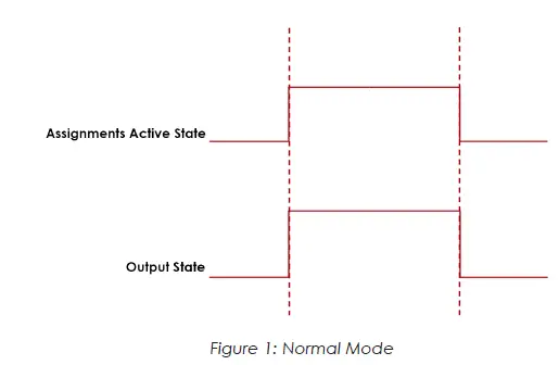
Timed
In the “Timed” mode the output will come on when the assignments state goes active and go off based on the time value or the assignment state going inactive (while still observing the polarity setting).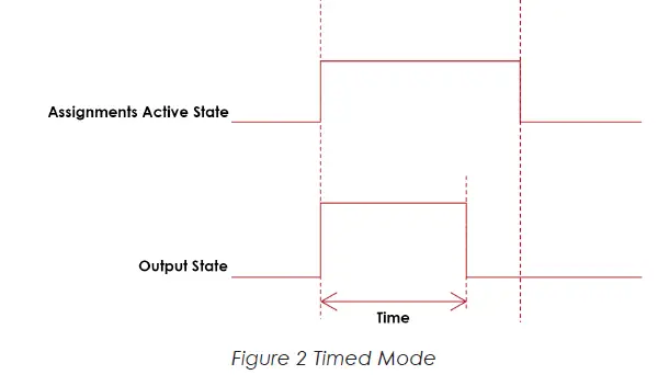
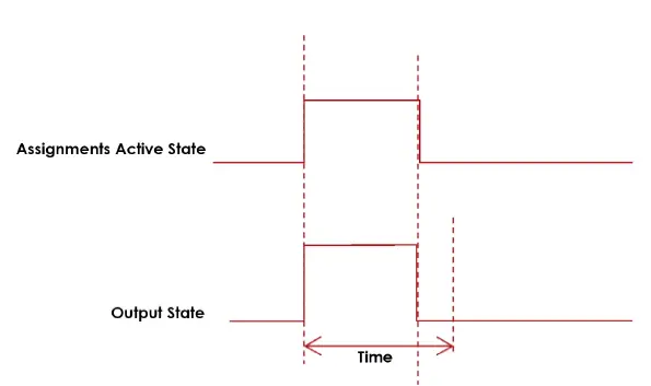 Figure 3: Timed Mode (assignment deactivates before time expires)
Flash
In the “flash” mode the output will flash at the time rate while the assignments state is active (while still observing the polarity setting).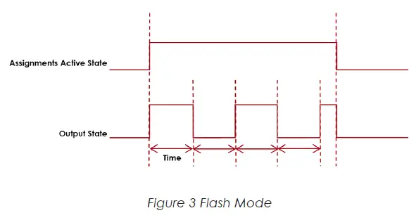
Width and Offset
For multiple bit outputs (for example “Running PSet Number”) the width variable defines the number of bits the assignment will output. This allows the output size to be restricted to a few bits saving space for other assignments.
The offset variable allows a fixed value to be added to the value before it is output.
For example to use bits 4 & 5 of the physical outputs to indicate the selected parameter set number 1-4 as binary 0-3 the assignment would look like…
| Running PSet Number | ||
| Bus | 1 | For the physical bus |
| Element | 0 | For the first element on the bus |
| Bit | 4 | For the starting bit location |
| Width | 2 | To span the two bits 4 & 5 |
| Offset | -1 | Adding -1 to the read input value so we get… 1 = Binary 00 2 = Binary 01 3 = Binary 10 4 = Binary 11 |
Output Assignments
| OK | Bus | Element | Bit 0-32 | Polarity N.O./N.C. | Mode: Normal, Timed, Flash | Time | Width | Offset | Input Bus | Input Element | Input Bit |
| √ | √ | √ | √ | √ | |||||||
| The “Ok” output assignment will go active at the completion of an acceptable fastening. It will go inactive when the next fastening is started (the torque exceeds the threshold value) or a Job reset. | |||||||||||
| Nok | Bus | Element | Bit 0-32 | Polarity N.O./N.C. | Mode: Normal, Timed, Flash | Time | Width | Offset | Input Bus | Input Element | Input Bit |
| √ | √ | √ | √ | √ | |||||||
| The “Nok” output assignment will go active at the completion of an unacceptable fastening. It will go inactive when the next fastening is started (the torque exceeds the threshold value) or a Job reset. | |||||||||||
| Torque Ok | Bus | Element | Bit 0-32 | Polarity N.O./N.C. | Mode: Normal, Timed, Flash | Time | Width | Offset | Input Bus | Input Element | Input Bit |
| √ | √ | √ | √ | √ | |||||||
| The “Torque Ok” output assignment will go active at the completion of a fastening that has an acceptable torque value. It will go inactive when the next fastening is started (the torque exceeds the threshold value) or a Job reset. | |||||||||||
| Torque Nok | Bus | Element | Bit 0-32 | Polarity N.O./N.C. | Mode: Normal, Timed, Flash | Time | Width | Offset | Input Bus | Input Element | Input Bit |
| √ | √ | √ | √ | √ | |||||||
| The “Torque Nok” output assignment will go active at the completion of a fastening that has an unacceptable torque value. It will go inactive when the next fastening is started (the torque exceeds the threshold value) or a Job reset. | |||||||||||
| Low Torque | Bus | Element | Bit 0-32 | Polarity N.O./N.C. | Mode: Normal, Timed, Flash | Time | Width | Offset | Input Bus | Input Element | Input Bit |
| √ | √ | √ | √ | √ | |||||||
| The “Low Torque” output assignment will go active at the completion of a fastening that has a low torque results. It will go inactive when the next fastening is started (the torque exceeds the threshold value) or a Job reset. | |||||||||||
| High Torque | Bus | Element | Bit 0-32 | Polarity N.O./N.C. | Mode: Normal, Timed, Flash | Time | Width | Offset | Input Bus | Input Element | Input Bit |
| √ | √ | √ | √ | √ | |||||||
| The “High Torque” output assignment will go active at the completion of a fastening that has a high torque results. It will go inactive when the next fastening is started (the torque exceeds the threshold value) or a Job reset. | |||||||||||
| Angle Ok | Bus | Element | Bit 0-32 | Polarity N.O./N.C. | Mode: Normal, Timed, Flash | Time | Width | Offset | Input Bus | Input Element | Input Bit |
| √ | √ | √ | √ | √ | |||||||
| The “Angle Ok” output assignment will go active at the completion of a fastening that has an acceptable angle results. It will go inactive when the next fastening is started (the torque exceeds the threshold value) or a Job reset. | |||||||||||
| Angle Nok | Bus | Element | Bit 0-32 | Polarity N.O./N.C. | Mode: Normal, Timed, Flash | Time | Width | Offset | Input Bus | Input Element | Input Bit |
| √ | √ | √ | √ | √ | |||||||
| The “Angle Nok” output assignment will go active at the completion of a fastening that has an unacceptable angle results. It will go inactive when the next fastening is started (the torque exceeds the threshold value) or a Job reset. | |||||||||||
| Low Angle | Bus | Element | Bit 0-32 | Polarity N.O./N.C. | Mode: Normal, Timed, Flash | Time | Width | Offset | Input Bus | Input Element | Input Bit |
| √ | √ | √ | √ | √ | |||||||
| The “Low Angle” output assignment will go active at the completion of a fastening that has a low angle results. It will go inactive when the next fastening is started (the torque exceeds the threshold value) or a Job reset. | |||||||||||
| High Angle | Bus | Element | Bit 0-32 | Polarity N.O./N.C. | Mode: Normal, Timed, Flash | Time | Width | Offset | Input Bus | Input Element | Input Bit |
| √ | √ | √ | √ | √ | |||||||
| The “High Angle” output assignment will go active at the completion of a fastening that has high angle results. It will go inactive when the next fastening is started (the torque exceeds the threshold value) or a Job reset. | |||||||||||
| Fastening Complete | Bus | Element | Bit 0-32 | Polarity N.O./N.C. | Mode: Normal, Timed, Flash | Time | Width | Offset | Input Bus | Input Element | Input Bit |
| √ | √ | √ | √ | √ | |||||||
| The “Fastening Complete” output assignment will go active at the completion of a fastening. It will go inactive when the next fastening is started (the torque exceeds the threshold value) or a Job reset. | |||||||||||
| In Cycle | Bus | Element | Bit 0-32 | Polarity N.O./N.C. | Mode: Normal, Timed, Flash | Time | Width | Offset | Input Bus | Input Element | Input Bit |
| √ | √ | √ | √ | √ | |||||||
| The “In Cycle” output assignment will go active at the start of the fastening cycle (the torque exceeds the threshold value). It will go inactive when the fastening cycle ends. | |||||||||||
| Fastening Aborted | Bus | Element | Bit 0-32 | Polarity N.O./N.C. | Mode: Normal, Timed, Flash | Time | Width | Offset | Input Bus | Input Element | Input Bit |
| √ | √ | √ | √ | √ | |||||||
| The “Fastening Aborted” output assignment will go active at the completion of a fastening that was aborted by the system. It will go inactive when the next fastening is started (the torque exceeds the threshold value) or a Job reset. | |||||||||||
| Fastening Stopped | Bus | Element | Bit 0-32 | Polarity N.O./N.C. | Mode: Normal, Timed, Flash | Time | Width | Offset | Input Bus | Input Element | Input Bit |
| √ | √ | √ | √ | √ | |||||||
| The “Fastening Stopped” output assignment will go active at the completion of a fastening that was stopped by the user. It will go inactive when the next fastening is started (the torque exceeds the threshold value) or a Job reset. | |||||||||||
| Batch Complete | Bus | Element | Bit 0-32 | Polarity N.O./N.C. | Mode: Normal, Timed, Flash | Time | Width | Offset | Input Bus | Input Element | Input Bit |
| √ | √ | √ | √ | √ | |||||||
| The “Batch Complete” output assignment will go active at the completion of a fastening that satisfies the bolt count of a Job sequence. It will go inactive when the next fastening is started (the torque exceeds the threshold value) or the job is reset. | |||||||||||
| Job Complete | Bus | Element | Bit 0-32 | Polarity N.O./N.C. | Mode: Normal, Timed, Flash | Time | Width | Offset | Input Bus | Input Element | Input Bit |
| √ | √ | √ | √ | √ | |||||||
| The “Job Complete” output assignment will go active at the completion of a fastening that satisfies all the sequences. It will go inactive when the next fastening is started (the torque exceeds the threshold value) or the job is reset. | |||||||||||
| Error | Bus | Element | Bit 0-32 | Polarity N.O./N.C. | Mode: Normal, Timed, Flash | Time | Width | Offset | Input Bus | Input Element | Input Bit |
| √ | √ | √ | √ | √ | |||||||
| The “Error” output assignment will be active while the controller has an error. | |||||||||||
| Tool Start Switch | Bus | Element | Bit 0-32 | Polarity N.O./N.C. | Mode: Normal, Timed, Flash | Time | Width | Offset | Input Bus | Input Element | Input Bit |
| √ | √ | √ | √ | √ | |||||||
| The “Tool Start Switch” output assignment will reflect the state of the tools start lever. | |||||||||||
| Tool Push to Start Switch | Bus | Element | Bit 0-32 | Polarity N.O./N.C. | Mode: Normal, Timed, Flash | Time | Width | Offset | Input Bus | Input Element | Input Bit |
| √ | √ | √ | √ | √ | |||||||
| The “Tool Push to Start Switch” output assignment will reflect the state of the tools push to start switch. | |||||||||||
| Tool MFB | Bus | Element | Bit 0-32 | Polarity N.O./N.C. | Mode: Normal, Timed, Flash | Time | Width | Offset | Input Bus | Input Element | Input Bit |
| √ | √ | √ | √ | √ | |||||||
| The “Tool MFB” output assignment will reflect the state of the tools multifunction button. | |||||||||||
| Tool Enabled | Bus | Element | Bit 0-32 | Polarity N.O./N.C. | Mode: Normal, Timed, Flash | Time | Width | Offset | Input Bus | Input Element | Input Bit |
| √ | √ | √ | √ | √ | |||||||
| The “Tool Enabled” output assignment will be active if the tool is enabled. | |||||||||||
| Tool Running | Bus | Element | Bit 0-32 | Polarity N.O./N.C. | Mode: Normal, Timed, Flash | Time | Width | Offset | Input Bus | Input Element | Input Bit |
| √ | √ | √ | √ | √ | |||||||
| The “Tool Running” output assignment will be active while the tool is running. | |||||||||||
| Service Indicator | Bus | Element | Bit 0-32 | Polarity N.O./N.C. | Mode: Normal, Timed, Flash | Time | Width | Offset | Input Bus | Input Element | Input Bit |
| √ | √ | √ | √ | √ | |||||||
| The “Service Indicator” output assignment will be active if the system is in need of service. | |||||||||||
| ToolsNet Connected | Bus | Element | Bit 0-32 | Polarity N.O./N.C. | Mode: Normal, Timed, Flash | Time | Width | Offset | Input Bus | Input Element | Input Bit |
| √ | √ | √ | √ | √ | |||||||
| The “ToolsNet Connected” output assignment will be active if the controller has an active connection to a ToolsNet server. | |||||||||||
| Open Protocol Connected | Bus | Element | Bit 0-32 | Polarity N.O./N.C. | Mode: Normal, Timed, Flash | Time | Width | Offset | Input Bus | Input Element | Input Bit |
| √ | √ | √ | √ | √ | |||||||
| The “Open Protocol Connected” output assignment will be active if the controller has an active Open protocol connection. | |||||||||||
| PFCS Connected | Bus | Element | Bit 0-32 | Polarity N.O./N.C. | Mode: Normal, Timed, Flash | Time | Width | Offset | Input Bus | Input Element | Input Bit |
| √ | √ | √ | √ | √ | |||||||
| The “PFCS Connected” output assignment will be active if the controller has an active PFCS connection. | |||||||||||
| Running PSet Number | Bus | Element | Bit 0-32 | Polarity N.O./N.C. | Mode: Normal, Timed, Flash | Time | Width | Offset | Input Bus | Input Element | Input Bit |
| √ | √ | √ | √ | √ | |||||||
| The “Running PSet Number” output assignment will output the current PSet number. | |||||||||||
| Running Job Number | Bus | Element | Bit 0-32 | Polarity N.O./N.C. | Mode: Normal, Timed, Flash | Time | Width | Offset | Input Bus | Input Element | Input Bit |
| √ | √ | √ | √ | √ | |||||||
| The “Running Job Number” output assignment will output the current Job number. | |||||||||||
| External Controlled | Bus | Element | Bit 0-32 | Polarity N.O./N.C. | Mode: Normal, Timed, Flash | Time | Width | Offset | Input Bus | Input Element | Input Bit |
| √ | √ | √ | √ | √ | √ | ||||||
| The “External Controlled” output assignment will reflect the state of an input. Use the “Input Bus, “Input Element”, and “Input Bit” to specify the input to reflect. | |||||||||||
| Tool in CCW | Bus | Element | Bit 0-32 | Polarity N.O./N.C. | Mode: Normal, Timed, Flash | Time | Width | Offset | Input Bus | Input Element | Input Bit |
| √ | √ | √ | √ | √ | |||||||
| The “Tool In CCW” output assignment will be active if the tool is put into disassembly mode and inactive if the tool is in assembly mode. | |||||||||||
| Tool in CW | Bus | Element | Bit 0-32 | Polarity N.O./N.C. | Mode: Normal, Timed, Flash | Time | Width | Offset | Input Bus | Input Element | Input Bit |
| √ | √ | √ | √ | √ | |||||||
| The “Tool In CW” output assignment will be active when the is in assembly mode and inactive if the tool is put into disassembly mode. | |||||||||||
| Torque | Bus | Element | Bit 0-32 | Polarity N.O./N.C. | Mode: Normal, Timed, Flash | Time | Width | Offset | Input Bus | Input Element | Input Bit |
| √ | √ | √ | √ | ||||||||
| The “Torque” output assignment will output the final torque value of the most recent rundown. The value will be cleared to 0 at the start of a new fastening cycle or a Job reset. At the end of the fastening cycle the final torque will be truncated to an integer and output. | |||||||||||
| Torque (x10) | Bus | Element | Bit 0-32 | Polarity N.O./N.C. | Mode: Normal, Timed, Flash | Time | Width | Offset | Input Bus | Input Element | Input Bit |
| √ | √ | √ | √ | ||||||||
| The “Torque (x10)” output assignment will output the final torque value of the most recent rundown. The value will be cleared to 0 at the start of a new fastening cycle or a Job reset. At the end of the fastening cycle the final torque will be multiplied by 10, truncated to an integer and output. | |||||||||||
| Torque (x100) | Bus | Element | Bit 0-32 | Polarity N.O./N.C. | Mode: Normal, Timed, Flash | Time | Width | Offset | Input Bus | Input Element | Input Bit |
| √ | √ | √ | √ | ||||||||
| The “Torque (x100)” output assignment will output the final torque value of the most recent rundown. The value will be cleared to 0 at the start of a new fastening cycle or a Job reset. At the end of the fastening cycle the final torque will be multiplied by 100, truncated to an integer and output. | |||||||||||
| Angle | Bus | Element | Bit 0-32 | Polarity N.O./N.C. | Mode: Normal, Timed, Flash | Time | Width | Offset | Input Bus | Input Element | Input Bit |
| √ | √ | √ | √ | ||||||||
| The “Angle” output assignment will output the final angle value of the most recent rundown. The value will be cleared to 0 at the start of a new fastening cycle or a Job reset. | |||||||||||
| Rundown Saved to FTP Server | Bus | Element | Bit 0-32 | Polarity N.O./N.C. | Mode: Normal, Timed, Flash | Time | Width | Offset | Input Bus | Input Element | Input Bit |
| √ | √ | √ | √ | ||||||||
| The “Rundown Saved to FTP Server” output assignment will output the ID of the last rundown that was saved to the FTP server. | |||||||||||
| Fastener Removed | Bus | Element | Bit 0-32 | Polarity N.O./N.C. | Mode: Normal, Timed, Flash | Time | Width | Offset | Input Bus | Input Element | Input Bit |
| √ | √ | √ | √ | √ | |||||||
| The “Fastener Removed” output assignment will go active when a fastener is removed by the operator. The controller must be configured to report disassembly for this output to work. It will go inactive when the next fastening is started (the torque exceeds the threshold value) or a Job reset. | |||||||||||
| Spindle OK | Bus | Element | Bit 0-32 | Polarity N.O./N.C. | Mode: Normal, Timed, Flash | Time | Width | Offset | Input Bus | Input Element | Input Bit |
| √ | √ | √ | √ | √ | |||||||
| The “Spindle Ok” output assignment will go active at the completion of multi-spindle fastening if all spindles have an OK. It will go inactive when the next fastening is started (the torque exceeds the threshold value) or a Job reset. | |||||||||||
| Spindle NOk | Bus | Element | Bit 0-32 | Polarity N.O./N.C. | Mode: Normal, Timed, Flash | Time | Width | Offset | Input Bus | Input Element | Input Bit |
| √ | √ | √ | √ | √ | |||||||
| The “Spindle NOk” output assignment will go active at the completion of multi-spindle fastening if one or more of the spindles have an NOK. It will go inactive when the next fastening is started (the torque exceeds the threshold value) or a Job reset. | |||||||||||
| Spindle Fastening Complete | Bus | Element | Bit 0-32 | Polarity N.O./N.C. | Mode: Normal, Timed, Flash | Time | Width | Offset | Input Bus | Input Element | Input Bit |
| √ | √ | √ | √ | √ | |||||||
| The “Spindle Fastening Complete” output assignment will go active at the completion of multi-spindle fastening. It will go inactive when the next fastening is started (the torque exceeds the threshold value) or a Job reset. | |||||||||||
| Pulses | Bus | Element | Bit 0-32 | Polarity N.O./N.C. | Mode: Normal, Timed, Flash | Time | Width | Offset | Input Bus | Input Element | Input Bit |
| √ | √ | √ | √ | ||||||||
| The “Pulses” output assignment will output the pulse count value of the most recent rundown. The value will be cleared to 0 at the start of a new fastening cycle or a Job reset. | |||||||||||
| Pulses High | Bus | Element | Bit 0-32 | Polarity N.O./N.C. | Mode: Normal, Timed, Flash | Time | Width | Offset | Input Bus | Input Element | Input Bit |
| √ | √ | √ | √ | √ | |||||||
| The “Pulses High” output assignment will go active at the completion of a fastening that has an pulse count that exceeds the high limit. It will go inactive when the next fastening is started (the torque exceeds the threshold value) or a Job reset. | |||||||||||
| Pulses Low | Bus | Element | Bit 0-32 | Polarity N.O./N.C. | Mode: Normal, Timed, Flash | Time | Width | Offset | Input Bus | Input Element | Input Bit |
| √ | √ | √ | √ | √ | |||||||
| The “Pulses Low” output assignment will go active at the completion of a fastening that has an pulse count that falls below the low limit. It will go inactive when the next fastening is started (the torque exceeds the threshold value) or a Job reset. | |||||||||||
| Pulses NOk | Bus | Element | Bit 0-32 | Polarity N.O./N.C. | Mode: Normal, Timed, Flash | Time | Width | Offset | Input Bus | Input Element | Input Bit |
| √ | √ | √ | √ | √ | |||||||
| The “Pulses Ok” output assignment will go active at the completion of a fastening that has an acceptable pulse count. It will go inactive when the next fastening is started (the torque exceeds the threshold value) or a Job reset. | |||||||||||
| Pulses Ok | Bus | Element | Bit 0-32 | Polarity N.O./N.C. | Mode: Normal, Timed, Flash | Time | Width | Offset | Input Bus | Input Element | Input Bit |
| √ | √ | √ | √ | √ | |||||||
| The “Pulses NOk” output assignment will go active at the completion of a fastening that has an unacceptable pulse count. It will go inactive when the next fastening is started (the torque exceeds the threshold value) or a Job reset. | |||||||||||
| ON | Bus | Element | Bit 0-32 | Polarity N.O./N.C. | Mode: Normal, Timed, Flash | Time | Width | Offset | Input Bus | Input Element | Input Bit |
| √ | √ | √ | √ | √ | |||||||
| The “ON” output assignment will be active when the controller is powered up and remains active until power down. | |||||||||||
| Job Aborted | Bus | Element | Bit 0-32 | Polarity N.O./N.C. | Mode: Normal, Timed, Flash | Time | Width | Offset | Input Bus | Input Element | Input Bit |
| √ | √ | √ | √ | √ | |||||||
| The “Job Aborted” output assignment will go active if a Job is aborted. It will go inactive when the job is reset. | |||||||||||
| Tool In Use | Bus | Element | Bit 0-32 | Polarity N.O./N.C. | Mode: Normal, Timed, Flash | Time | Width | Offset | Input Bus | Input Element | Input Bit |
| √ | √ | √ | √ | √ | |||||||
| The “Tool In Use” output assignment will go active when the trigger is pressed, whereupon a timer will restart. It will go inactive when the specified time is reached without becoming active in between. | |||||||||||
| Barcode Scanned | Bus | Element | Bit 0-32 | Polarity N.O./N.C. | Mode: Normal, Timed, Flash | Time | Width | Offset | Input Bus | Input Element | Input Bit |
| √ | √ | √ | √ | ||||||||
| The “Barcode Scanned” output assignment will go active when a barcode is scanned. The ID # (1-4) will activate the corresponding bit, if it is covered by the number of bits configured. The maximum size is 4 bits. All bits will go inactive when a tool reaches the InCycle threshold of a rundown or when they are reset. | |||||||||||
| Start Trigger Active | Bus | Element | Bit 0-32 | Polarity N.O./N.C. | Mode: Normal, Timed, Flash | Time | Width | Offset | Input Bus | Input Element | Input Bit |
| √ | √ | √ | √ | ||||||||
| The ‘Start Trigger Active’ assignment will reflect the state of the active Start Input configured to run the tool. | |||||||||||
The ‘Start Trigger Active’ assignment will reflect the state of the active Start Input configured to run the tool.
Possible Start Inputs include:
- Start from IO
- Start
- Dual Start Interlocked
- Start from Tool Buttons
- Lever and/or PTS
- Dual Levers Interlocked
- Start from Master Tool
- Start from Remote Start
- Latched Throttle
Start Trigger Active is available for the iEC Controller Only.
CORPORATE HEADQUARTERS 10000 SE Pine Street Portland, Oregon 97216
Phone: (503) 254–6600
Toll Free: 1-800-852-1368
AIMCO CORPORATION DE MEXICO SA DE CV Ave. Cristobal Colon 14529
Chihuahua, Chihuahua. 31125
Mexico
Phone: (01-614) 380-1010


