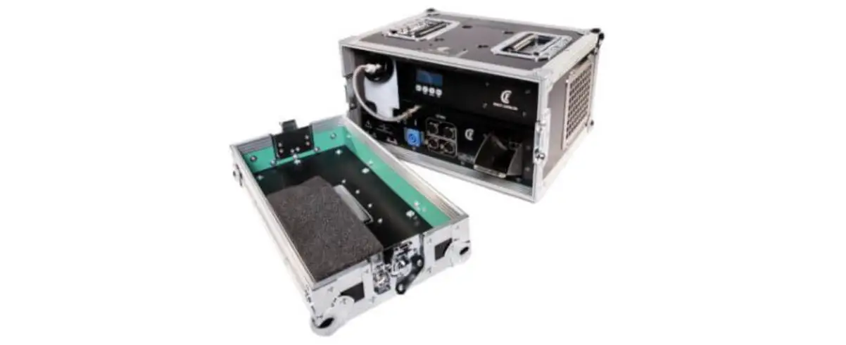
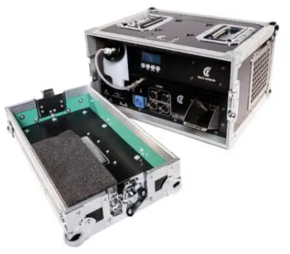
CLF LIGHTING CLF Haze I Built In Flight Case Touring Hazer
DIMENSIONS
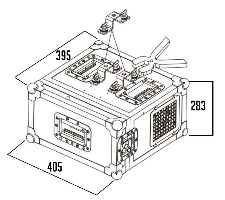
ALL DIMENSIONS ARE IN MILLIMETERS
MACHINE OVERVIEW
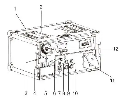
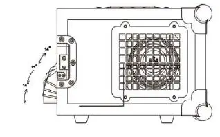
- Flightcase
- Hanging option
- Fluid container handle
- Fluid container fixation knob
- Fluid container fixation
- Fluid inlet
- Powercon input
- Breake
- 3 Pin OMX in/out
- 5 Pin OMX in/out
- Smoke output
- LCD display
SAFETY INSTRUCTION
The following symbols are used to identify important safety information on the product.

DANGER
Safety hazard
Risk of severe injury or death.
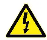
DANGER
Hazardous voltage
Risk of lethal or severe electric shock
WARNING
LED light emission.Do not eye injury.
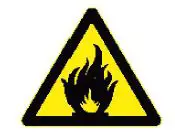
WARNING
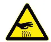
Burn hazard
Hotemission. Do not touch
WARNING
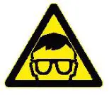
Wear protective eyewear
WARNING
Refer to user manual

USING FOR THE FIRST TIME
This product is for professional use only. It is not for household use. This product presents risks of severe injury or death due to fire and burn hazards, electric shock and falls.
Read this manual before installing, powering or servicing the fixture, follow the safety precautions listed below and observe all warnings in this manual and printed on the fixture. If you have questions about how to operate thefixture safely, please contact your supplier.
PROTECTION FROM ELECTRIC SHOCK
- Disconnect the machine from AC power before removing or installing any cover or part and when not in use.
- Always ground earth the fixture electrically.
- Use only a source of AC power that complies with local building and electrical codes and has both overload and ground-fault earth fault protection.
- Before using the machine check that all power distribution equipment and cables are in perfect condition and rated for the current requirements of all connected devices.
- Power input and throughput cables must be rated 20 A minimum, have three conductors 1.5 mm 16 AWG minimum conductor size and an outer cable diameter of 5 – 15 mm.
- Cables must be hard usage type SJT or equivalent) and heat-resistant to 90° C minimum.
- Use only PowerCON cable connectors to connect to power input sockets.
- Use only PowerCO cable connectors to connect to power through put sockets.
- Isolate the machine from power immediately if the power plug or any seal, cover, cable, or other component is damaged, defective, deformed, wet or showing signs of overheating.
- Do not reapply power until repairs have been completed.
DO NOT EXPOSE THE FIXTURE TO RRIN OR MOISTURE
CLF Haze II has an IP20 rating, indoor use only.
SAFETY INSTRUCTION
PROTECTION FROM BURNS RNO FIRE
- Do not operate the machine if the ambient temperature (Ta) exceeds 45 ° C.
- The exterior of the machine becomes hot during use.
- Avoid contact by persons and materials.
- Allow the machine to cool for at least 1 0 minutes before handling.
- Keep all combustible materials e.g. fabric, wood, paper at least 100 mm away from the nozzle
- Keep flammable materials well away from the machine
- Ensure that there is free and unobstructed airflow around the machine
- Do not place objects within 200 mm of the machine
- Do not attempt to bypass thermostatic switches or fuses.
- If you relay power from one machine to another using power throughput sockets, do not connect more than1 machines in total to each other in an interconnected chain.
- Connect only other machines to fixture power throughput sockets. Do not connect any other type of device
to these sockets. - Do not connect any other type of device to these sockets.
- Do not stick filters, masks or other materials onto any optical component.
- Do not modify the machine in any way not described in this manual
- Do not connect machine to a dimmer
PROTECTION FROM INJURY
- Fasten the fixture securely to a fixed surface or structure when in use.
- The fixture is not portable when installed.
- Ensure that any supporting structure and/or hardware used can hold at least 10 times the weight of all the devices they support.
- Allow enough clearance around the head to ensure that it cannot collide with an object or another fixture when it moves.
- Check that all external covers and rigging hardware are securely fastened.
- Block access below the work area and work from a stable platform whenever installing, servicing or moving the machine
- Do not operate the machine with missing or damaged covers, shields or any optical component.
RC POWER
POWER VOLTAGE
Check that the voltage range specified on the machine serial number label matches the local AC mains power voltage before applying power to the fixture. The machine accepts AC mains power at 100-240 V nominal. 50/60 Hz. Do not apply AC mains power to the machine at any other voltage than specified.
POWER CABLES
Power input and throughput cables must be rated 20 A minimum, have three conductors 1.5 mm 2 (16 AWG) minimum conductor size and an outer cable diameter of 5 – 15 mm. Cables must be hard usage type (SJT or equivalent) and heat- resistant to so·c minimum. In the EU the cable must be HAR approved or equivalent. If you install a power plug on the power cable, install a grounding-type (earthed) plug that is rated 20 A minimum. Follow the plug manufacturer’s instructions standard wire color coding schemes and some possible pin identification schemes; if pins are not clearly identified, or if you have any doubts.
Wire color coding and power connections
| Wire color EU models | Wire color US models | Conductor | Symbol | Screw(US) |
| Brown | Black | Live | L | Yellow or Brass |
| Blue | White | Neutral | N | Silver |
| Yellow / green | Green | Ground (earth) | Green |
DATA LINK
A DMX 512 data link is required in order to control a machine via DMX. The machine has 3 & 5-pin XLR connectors for DMX data input and output. The pin-out on all connectors is pin 1 = shield, pin 2 = cold – and pin 3 = hot + Pins 4 and 5 in the 5-pin XLR connectors are not used.
TIPS FOR RELIABLE DATR TRANSMISSION
To connect the machine to data:
- Connect the DMX data output from the controller to the closest machines male 3 & 5-pin XLR DMX input connector.
- Connect the DMX output of the machine closest to the controller to the DMX input of the next machine and continue connecting machines output to input.
PHYSICAL INSTALLATION
Warning
The machine must be either fastened to a flat surface such as a stage or wall, or clamped to a truss or similar structure in any orientation using a rigging clamp. At all times machine can cause injury or damage it if falls, attach an approved safety cable to one of the safety cable attachment points on the base. Check that all surfaces more far aways then a minimum of 200 mm. from the machine, that combustible materials wood, fabric, paper, etc are minimum 100 mm. from the nozzle, that there is free airflow around the machine and that there are no flammable materials nearby.
FRSTENING THE MRCHINE TO R FLRT SURFRCE
The machine can be fastened to a fixed flat surface that is oriented at any angle. Check that the surface can support at least 10 times the weight of all machines and equipment to be installed on it.
Warning
The supporting surface must be flat otherwise the air vents in the base may be blocked, which will cause overheating. Fasten the machine securely. Do not place it on a surface or leave it where it can be moved or can fall over. Attach a securely anchored safety cable to the safety cable attachment point. If the machine is installed in any location where ii may fall and cause injury or damage if the primary attachment fails
- Block access under the work area. Working from a stable platform.
- Secure the machine with a secondary attachment such as an approved safety cable that is rated for the weight of the machine using one of the attachment points at the edges of the base.
- Do not use any other part of the machine as a safety cable attachment point.
OPERATING INSTRUCTIONS
- After checking that all the parts are intact and complete, position the machine on a flat surface.
- Only use designated CLF Lighting haze liquid.
- Machine can be harmed when using other fluids and warranty is expired.
- Connecting the power cord.
- Before power on, make sure it is connected with the rated voltage.
- Tum on the machine, it will immediately start heating up, the digital display will show WARMING UP.
- MENU button: When it shows HEAT, press menu button to enter the page ADDR.
- UP button: Increase the relevant value of each page.
- DOWN button: Decrease the relevant value of each page.
- ENTER button: Enter or exit each page.
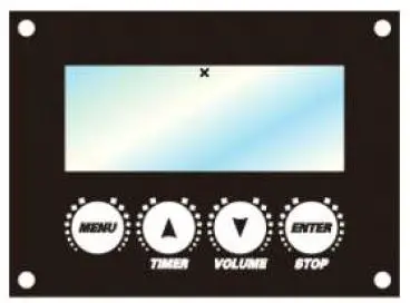
- MENU:Scroll through setting menu
- UP:Increase, multiplex TIMER button.
- DOWN:Decrease, multiplex VOLUME button;
- ENTER:In/Out, multiplex stop button.
Press MENU button to switch different menu options!:
- Ready To Fog: The machine is ready to work
- Interval Set: To set the interval of timer mode , adjustable from 5-200s
- Duration Set: To set the duration of timer mode , adjustable from 5-200s
- Timer out: Set the haze fog output from 1 – 100% under Timer mode
- Volume out: Set the haze fog output from 1 – 100% under Volume mode
- Fan speed: Set the fan speed from 1 – 100%
- DMX512 Address: The DMX address can be set up from 1 to 512
- Direct timer: Direct timer on / off after power on
- Language: Select the language saved by Enter
- Under any setting pages, press STOP to exit or return to the page one.
- When the unit is working, press STOP to stop running and return to the page one.
- After enter into different setting pages, press UP and DOWN to change the value.
- When it is in the page one, press TIMER button to enter into timer mode.
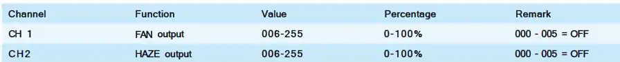
OMX CHANNELS
MAINTENANCE
Fluid injection trouble
Refers to the fog fluid atomizing in the heater pipe of the machine is not good, heater temperature cannot be timely and effective transmit to the fog fluid, fog fluid cannot all atomization and lead to fluid injection.
- Using the low quality or counterfeit fog fluid, low quality fog fluid have more impurities, easy to adhere to the pipe wall and hindered temperature transmission result in incomplete atomization caused fluid injection.
- Using an incorrect fog fluid. Different fog fluid have different required atomization If you use the wrong fog fluid result in oil cannot fully atomization caused fluid injection.
Heater blocking trouble
Poor atomization fluid injection is the early signs of heater block. Using no CLF quality fog fluid or not timely maintenance cleaning the fog machine for a long time. Inevitable will appear the terminal symptom of heater blocking.
- heater blocked is because used inferior fog fluid or not maintenance for a long time.
- Have nothing to do with the quality of machine. Like a car with poor quality gasoline produce poor fluid circuit failure or long-time no maintenance the car will inevitably appear bigger problems.
Solutions to these problems
Fog machine heating pipes used for a long time and then the pipe wall will easily produce sediments. The more inferior fog fluid the more impurities thus lead to fluid injection or blocked. All fog machines need regular maintenance (fog machine maintenance cycle for 1 to 2 months/time. Specific maintenance method: after heating the 35% white vinegar plus 65% distilled water and then spray 10 to 15 time
Conclusion
As long as the fog machine with fluid injection or heater blocking after using a period of lime. It was caused by fog fluid quality or lack of maintenance, has nothing to do with the quality of the machine. Please use the CLF original high quality fog fluid and timely maintain it, then it can be used for a long time.
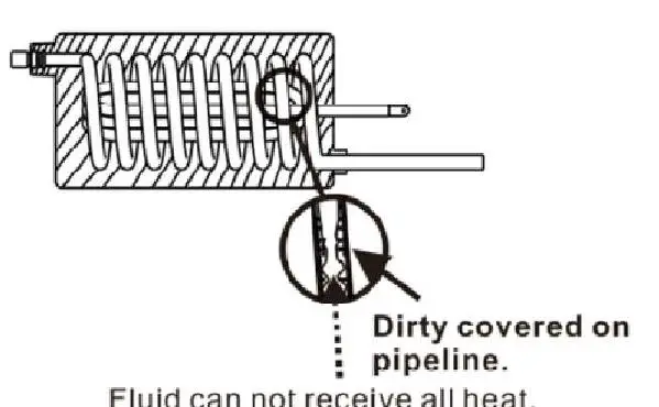
Pipeline has covered by dirt, insufficient heat transfer result in water spraying
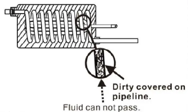
Pipeline has covered by dirt, that results in blocked heater
EXPLODED VIEW
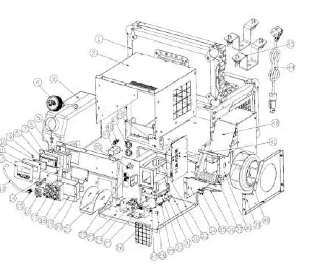
| Empty flight case | CLF-70-075 | 26 | Filter air direction | CLF-70-100 | |
| 2 | Top cover | CLF-70-076 | 27 | Copper connector fluid pump | CLF-70-065 |
| 3 | Fluid container | CLF-70-077 | 28 | Copper cap fluid pump | CLF-70-066 |
| 4 | Fluid cap | CLF-70-078 | 29 | Straight connector fluid line | CLF-70-103 |
| 5 | Front plate | CLF-70-079 | 30 | Air pump support plate | CLF-70-061 |
| 6 | LCD cover | CLF-70-042 | 31 | Airline | CLF-70-105 |
| Display seal | CLF-70-081 | 32 | Air pump | CLF-70-063 | |
| Display PCB | CLF-70-082 | 33 | Air pump clip | CLF-70-037 | |
| 9 | Plastic display support | CLF-70-017 | 34 | Left cover plate turbo fan | CLF-70-108 |
| 10 | Display glass | CLF-70-084 | 35 | Thermostat | CLF-70-058 |
| 11 | Display support plate | CLF-70-016 | 36 | Heat filter | CLF-70-059 |
| 12 | Display sticker | CLF-70-015 | 37 | Fast heater | CLF-70-060 |
| 13 | Spring fluid line | CLF-70-087 | 38 | Turbo fan mounting plate | CLF-70-112 |
| 14 | Fuse | CLF-70-051 | 39 | Right cover plate turbo fan | CLF-70-113 |
| 15 | Copper cap fluid line | CLF-70-089 | 40 | Turbo fan | CLF-70-114 |
| 16 | Powercon input socket blue | CLF-70-010 | 41 | Main PCB | CLF-70-115 |
| 17 | 3-pin OMX PCB (male/female) | CLF-70-019 | 42 | Top cover plate turbo fan | CLF-70-116 |
| 18 | 5-pin OMX PCB (male/female) | CLF-70-009 | 44 | Schuko-Powercon aansluitkabel 3x1,Smm2, | 1.8 meter |
| 19 | Cover OMX PCB’s | CLF-70-093 | 45 | Hanging bracket | CLF-70-117 |
| 20 | Name plate | CLF-70-094 | 46 | Alu. Heat sink main PCB | CLF-70-118 |
| 21 | Air director | CLF-70-095 | 47 | Plastic clip | CLF-70-119 |
| 22 | Tee connector fluid line | CLF-70-096 | 48 | Copper joint fluid line | CLF-70-050 |
| 23 | Bottom cover | CLF-70-097 | 49 | Mains filter | CLF-70-121 |
| 24 | Fluid pump | CLF-70-064 | 50 | Tee connector clip | CLF-70-122 |
SPECIFICATIONS
| Power hazer | 850W |
| Power heater | 800W |
| Voltage I frequency | AC1DOV – 240V – 50/60Hz |
| Fuse | 8A/250V |
| AC power input | PowerCON |
| DMX data in/out | 5 pin & 3 pin locking XLR |
| Netto weight | 15,3kg |
| Size | 425x390x242mm |
| Control | DMX |
| Channel | 2 channels |
| Output | 6000CUFT/MIN |
| Settings and addressing | control panel with backlit LED graphic display |
| Protocol | USITT DMX512-A |
| Housing color | Black flightcase |
| Housing | High strenght die-casting aluminium and metal |
| Protection rating | IP20 |
| Orientation | Floor & hanging |
| Min distance to combustable materials | 50mm from machine |
| Min distance to iluminated surfaces | 100mm from machine |
| Wireless remote | No |
| Fluid consumption | 10ml/min. |
| Fluid capacity | 3,SL |
| Fluid brand | CLF Haze fluid |
| Heat up time | 50-100 sec |
| Max ambient temperature Ta max | 4s0c |


